



Abstract
Objective
To develop a reproducible method of using radiofrequency-induced thermotherapy with adequate thermal spread to ablate the whole vein wall in a truncal vein but avoiding carbonisation, device sticking and high impedance “cut outs” reducing interruptions during endovenous treatments.
Methods
Porcine liver was treated with radiofrequency-induced thermotherapy under glass to allow measurements, observation and video recording. Powers of 6–20 W were used at varying pullback speeds to achieve linear endovenous energy densities of 18–100 J/cm. Thermal spread, carbonisation of treated tissue and high-impedance cut outs were recorded.
Results
The currently recommended power settings of 18 and 20 W produced sub-optimal results. If pulled back at 3 s/cm to achieve linear endovenous energy densities around 60 J/cm, tissue carbonisation and high impedance cut outs occurred. When high powers and fast pullbacks of 1 s/cm were used, no carbonisation or cut outs occurred but thermal ablation of the liver model was below target due to reduced time for thermal conduction. Low powers (6–12 W) with slow pullbacks (6–12 s/cm) achieved target thermal ablation with minimal carbonisation and high impedance cut outs.
Conclusions
Using low power (6 W) and a slow discontinuous pullback (6 s every 0.5 cm, in steps), we were able to achieve our target thermal ablation in the porcine liver model without carbonisation and high impedance cut outs. This suggests the currently recommended power levels could be reduced, reducing the need to remove the device to clean the electrodes during treatment while achieving target thermoablation of the treated tissue.
Introduction
Varicose veins make up a large portion of the workload at every vascular unit. Half of all people over 50 years of age have some signs of venous disease and half of those people have varicose veins. 1 The traditional treatment for varicose veins, the high saphenous tie and strip, have been shown to be associated with several problems including pain, bruising, time off of work, large scars, general anaesthesia and neovascularisation. 2 These have led to the development of minimally invasive techniques with the aim of permanently destroy incompetent veins. Catheter-based endovenous thermoablation is now the recommended first-line treatment for truncal reflux in the United Kingdom. 3
Radiofrequency-induced thermotherapy (RFiTT) (Olympus Europa, Hamburg) is a catheter-based thermo-ablative endovenous treatment for refluxing truncal veins. The RFiTT catheter uses a bipolar radiofrequency current, having two circumferential electrodes at its tip with a small gap between them. When in contact with the vein wall, alternating current passes between the electrodes at radiofrequency rates. Heat is not generated by the electrodes themselves, it is generated by the resistance of the surrounding tissue to the passage of the alternating current. The impedance of the tissue, not the temperature, is constantly measured by the RFiTT device, which feeds this information back to the operator via an audible pitch-based signal. There is no independent referenced data at this time regarding in vivo temperatures reached in RFiTT treatment.
The impedance is measured between the electrodes and hence changes in the impedance reflect changes in the intima. During treatment, the intima starts to desiccate due to the heat and the impedance increases. The RFiTT monitor constantly measures this impedance and provides feedback to the operator via an audible tone. As the tissue desiccates further, the impedance increases and the tone increases in pitch until it reaches a level where the generator automatically cuts out as a safety measure.
Unfortunately, the measured impedance is not the impedance of the whole vein wall but the impedance of the innermost layers of the vein wall – intima and perhaps the innermost part of the media. In addition, the quicker the energy is applied to the vein (i.e. the higher the power), the quicker the intima desiccates, the quicker the impedance rises and the less chance there is for the heat to penetrate the vein wall to ablate the whole of the media layer. As such, high impedance cut outs before an adequate linear endovenous energy density (LEED) has been reached represents an inadequate treatment of the vein wall and if these cut outs keep happening during a treatment, they become very irritating for the operating doctor.
Previous thermoablation studies have shown good levels of closure of great saphenous veins (GSV) with a LEED > 60 J/cm both in RFiTT 4 and endovenous laser therapy. 5 However, current literature on RFiTT favours high power levels between 18 and 25 W both in ex vivo experiments 6 and in clinical trials,7–9 with withdrawal rates of approximately 1.0 s/cm giving an LEED of only 20 J/cm. There seems to be no clear justification for this recommendation in veins other than experience with previous generations of this technology used in other areas such as tumour ablation 10 and the ex vivo work looking for circumferential necrosis seen on histology. 6
Despite published clinical studies reporting closure rates 88.9–98.9%, one study concluded that RFiTT needed “improvement in treatment parameters” 8 and two of the studies showed that slowing down the pullback resulted in higher rates of occlusion,7,9 and the best results reported achieving the high levels of occlusion only when the results from “inexperienced” operators (<20 cases) were excluded. 9 Very little data has been published as to why the current treatment parameters are sub-optimal 8 or why “inexperienced” operators get poor results and need to be excluded from a study. 9 However, a recent publication has shown that using high powers and fast pullbacks, multiple passes might be needed for optimal results and has identified removing the catheter for cleaning as a problem. 11
The aim of this study was to develop a reproducible method of using RFiTT in an in vitro model that can achieve an LEED of >60 J/cm but without causing the catheter to stick to the tissue being treated, carbonisation or high impedance cut outs, all of which are associated with the currently recommended high power settings of 18–25 W.
Methods
A ProCurve 1200-S15 (Olympus, Hamburg) applicator was used with the CelonLab Precision RFiTT power generator (Olympus, Hamburg). Porcine liver was treated with RFiTT under glass. This enabled the observation and high-resolution photographic documentation of the effect of different withdrawal speeds and power settings.
The method of treatment was as follows. Fresh Porcine liver was placed on a laboratory surface. The liver was covered liberally with normal saline. A ruler marked in centimetres with millimetre divisions was placed on the liver surface. Close by, and parallel to this ruler, the RFiTT catheter was placed on the liver surface. More normal saline was spread over the area and a sheet of glass placed on top of the liver, ruler and RFiTT catheter. The weight of the glass flattened the liver surface and pushed the RFiTT catheter into the liver tissue, ensuring the catheter was surrounded by liver on three sides – only the side adjacent to the glass was free of contact with liver tissue. Thus thermal spread from the edge of the RFiTT catheter could be observed spreading above and below the catheter, giving a view as if in cross-section of tissue being treated.
The camera mounted above the glass recorded these thermal spreads as the RFiTT catheter was set to different powers and different pullback speeds were used.
Regardless of power or pullback, each treatment length was 5 cm. All catheter pullbacks were smooth and continuous with the exception of the final “discontinuous” method we developed in order to make the technique easier to perform and for others to reproduce.
Settings used in this study classified by increasing LEED.
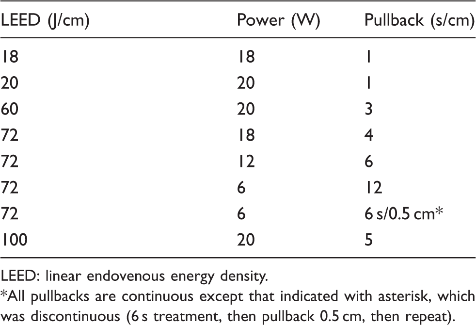
LEED: linear endovenous energy density.
All pullbacks are continuous except that indicated with asterisk, which was discontinuous (6 s treatment, then pullback 0.5 cm, then repeat).
All withdrawals were carried out by a surgeon experienced with endovenous techniques. Carbonisation, characterised by black carbon being visible in the treated tissue, sticking of the electrodes to the burnt tissue and high impedance generator cut outs were noted. Carbonisation was deemed as “unacceptable” when the carbon had accumulated sufficiently to cause a high impedance cut out and the catheter had to be removed and cleaned before treatment could be continued. High-resolution photographs were taken of each treatment with a Dermascope camera. This allowed the thermal spread to be measured by using pixel to millimetre conversion. Thermal spread was measured at seven sites on each treatment tract, measurements being made 0.5 cm apart. The first and last centimetres of treatment were excluded to reduce error. The standard error of each data set was used to compare the data and judge the possible statistical significance. Four different pullbacks were used for each power and pullback setting giving 20 measurements in total for each setting.
The thickness of the saphenous vein wall has been found to be highly variable but has been documented as being between 0.18 and 0.65 mm. 12 Knowing the similarity of the thermal spread in our model compared with GSV (see above), and knowing that we wanted to achieve transmural ablation of the vein wall in every patient to be happy we had optimal treatment of the vein, 13 we set the target for “adequate treatment” for this study to achieve visible thermoablation of the porcine liver to spread at least 0.65 mm laterally from the edge of the treatment electrodes on the RFiTT device.
The measurements of thermal spread between the different settings were plotted on a graph with error bars ±2 SD from the norm for ease of seeing statistical differences between the groups at the 95% confidence interval and results were also analysed for statistical significance using the Student's t-test for parametric continuous data.
Results
Carbonisation of tissue, catheter sticking and high impedance cut outs
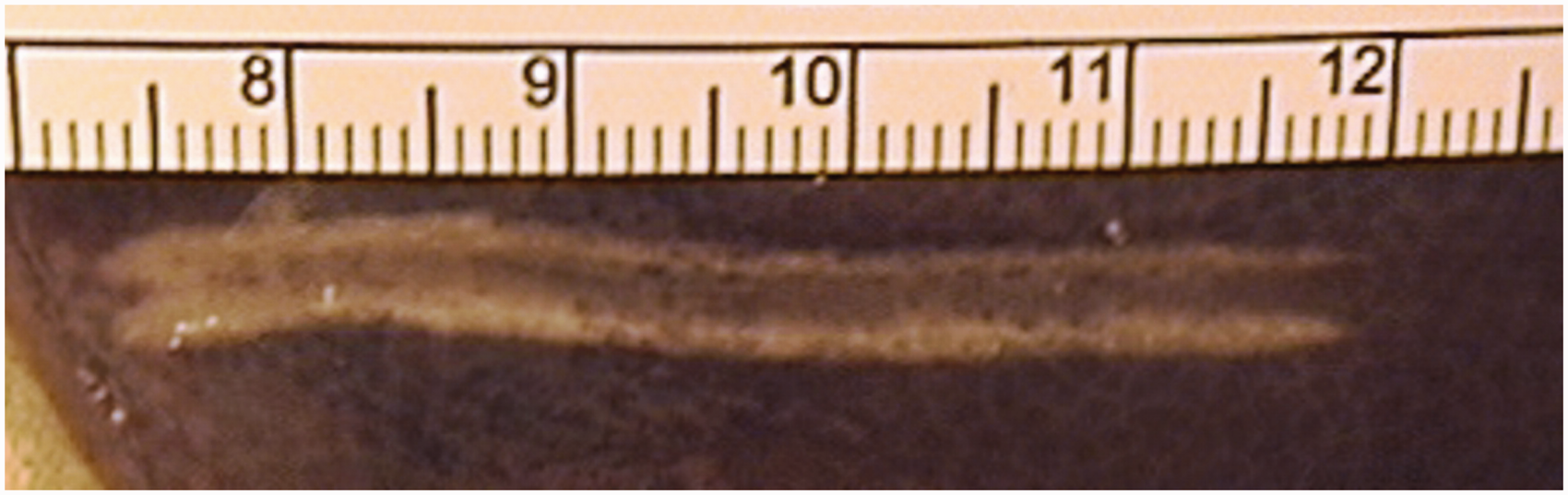
A power level of 20 W with a pullback speed of 5 s/cm (LEED = 100 J/cm) produced an unacceptable level of carbonisation, constant sticking of the electrodes to the treated tissue and almost continuous high impedance cut outs (Figure 1). Therefore this setting was not repeated. Other high impedance related cut outs were observed five times in the 18 W at 4 s/cm (LEED = 72 J/cm) (Figure 2) and once in the 20 W at 3 s/cm (LEED = 60 J/cm) (Figure 3). At these two settings, we also observed some carbonisation of the tissue with occasional sticking of this tissue to the electrodes.
Porcine liver treated with RFiTT at 20 W with pullback of 5 s/cm (LEED = 100 J/cm). Continuous high impedance cut outs made it impossible for the operator to use these settings. Tissue carbonisation is clearly seen in the treatment tract. Treatment settings of 18 W with a pullback of 4 s/cm (LEED = 72 J/cm). These settings produced high impedance cut outs and a low thermal spread in the tissue. Some tissue carbonisation is seen in the treatment tract. Treatment settings of 20 W with a pullback of 3 s/cm (LEED = 60 J/cm). These settings showed that the target thermal spread had been achieved but some high impedance cut outs were experienced with some tissue carbonisation and device sticking.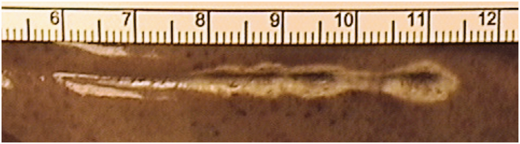
None of the other settings tested caused carbonisation of the tissues, catheter sticking nor had any high impedance cut outs.
Thus of the settings tested (see Table 1), the three settings with the recommended powers for RFiTT treatment (18 or 20 W) with pullbacks designed to make sure the LEED is > 60 J/cm, all showed problems of tissue carbonisation, catheter sticking to tissue and high impedance cut outs. The only two settings at these power levels that did not cause these problems of over burning the test tissue were those that had such quick pullbacks, that the LEED dropped to 18 and 20 J/cm, both levels significantly below the LEED needed for confident closure of the GSV.
In contrast, all of the settings using lower powers and slower pullbacks managed to achieve LEEDs of 72 J/cm without any carbonisation of test tissue, catheter sticking or high impedance cut outs.
Thermal spread
The thermal spread results are shown graphically with error bars ±2 SD from the norm (Figure 4). At LEEDs of 18 J/cm (Figure 5) and 20 J/cm (Figure 6), there was <0.5 mm of thermal spread laterally from the edge of the RFiTT device. Using our cut off of 0.65 mm as above, these two settings failed to achieve our target thermal spread from the device.
A graph to show the mean thermal spread at each tested setting. Error bars ± 2 SD from the norm. Only LEEDs >60 J/cm showed thermal spread in the tissues that reached our target of 0.65 mm (see text). Treatment settings of 18 W with a pullback of 1 s/cm (LEED = 18 J/cm). This setting shows inadequate thermal spread in the tissue to reach our target of 0.65 mm (see text). Treatment settings of 20 W with a pullback of 1 s/cm (LEED = 20 J/cm). This setting shows inadequate thermal spread to reach our target of 0.65 mm (see text).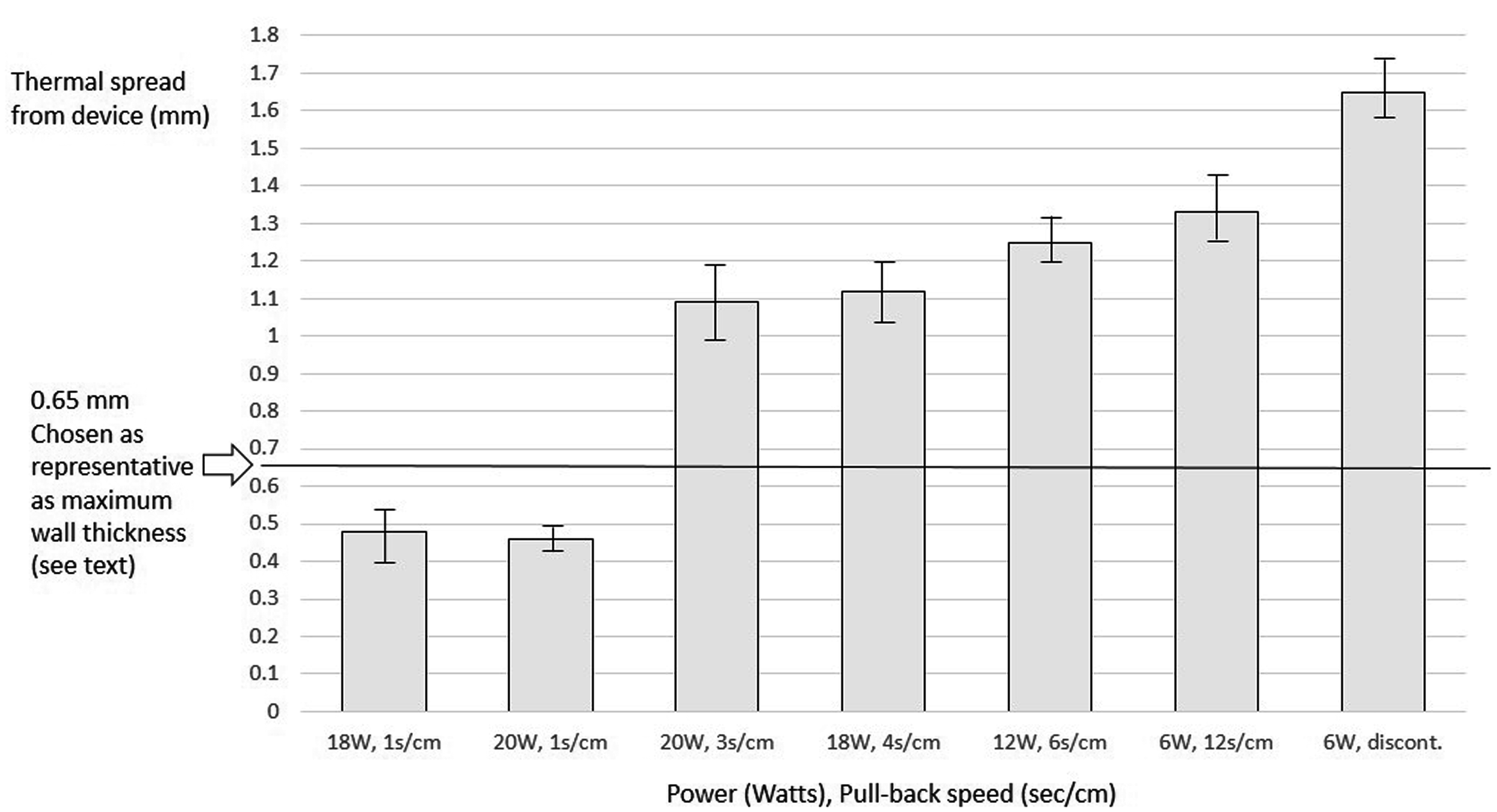
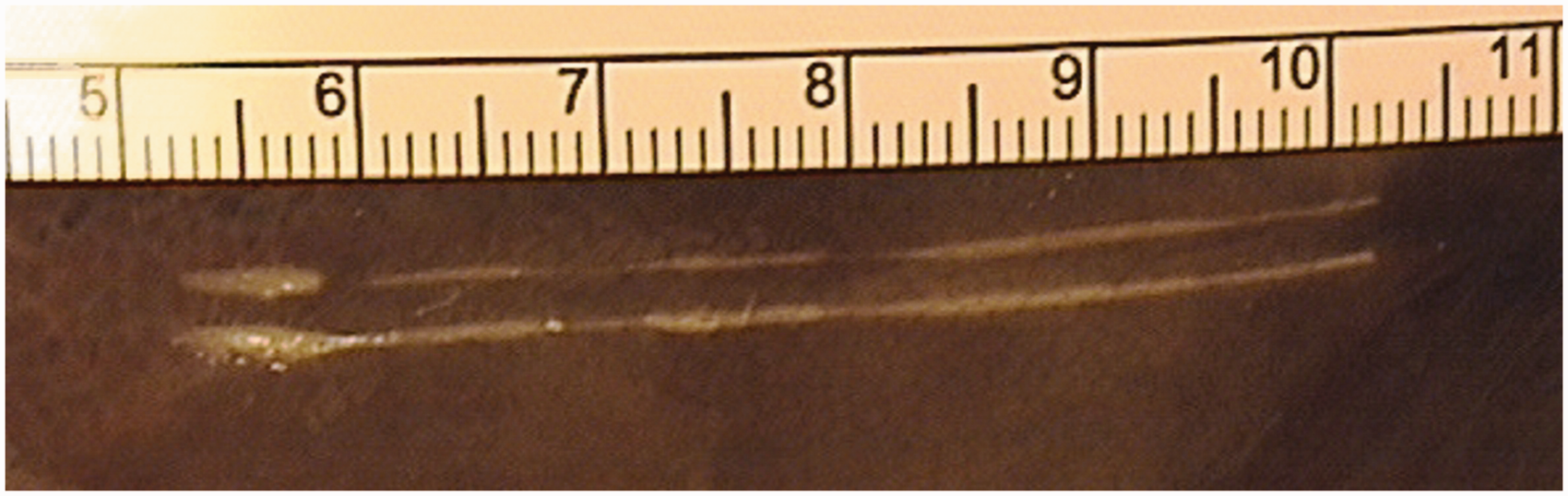
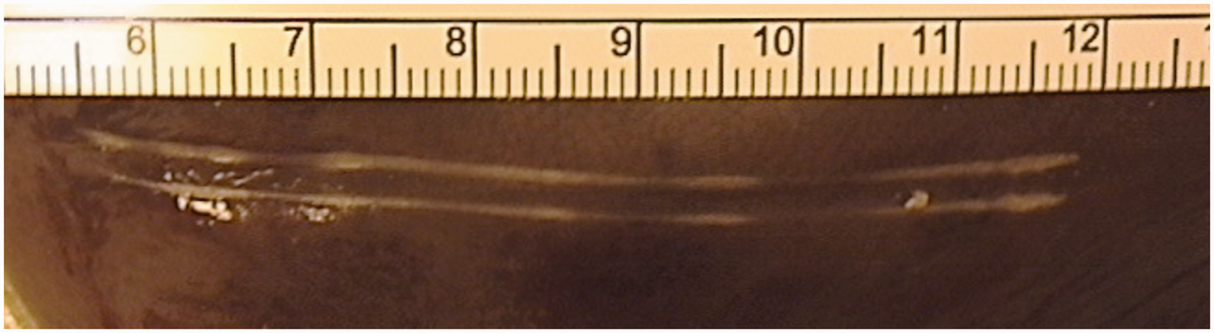
All LEEDs >60 J/cm showed thermal spread >1.0 mm laterally from the edge of the RFiTT device. As can be seen graphically in Figure 4, the techniques using slower pullback speeds had larger thermal effect radii, even though they used lower powers. This shows that slower rates of application of thermal energy allow further thermal spread in the tissue surrounding the device. However, the difference between the 20 W at 3 s/cm (LEED = 60 J/cm) (Figure 3) and the 18 W at 4 s/cm (LEED = 72 J/cm) (Figure 2) methods was not significant (p > 0.05).
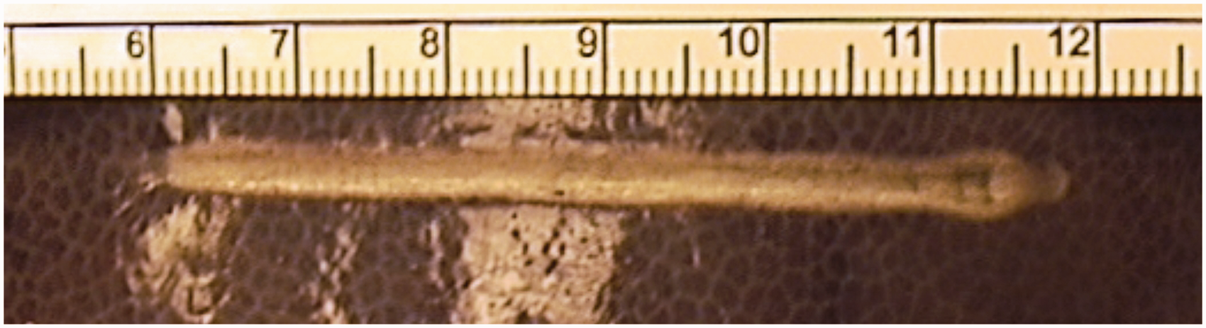
The 12 W at 6 s/cm (LEED = 72 J/cm) (Figure 7) and 6 W at 12 s/cm (LEED = 72 J/cm) (Figure 8) settings did not show any significant difference of thermal spread. However, both were more effective than the 18 W at 4 s/cm (LEED = 72 J/cm) method (Figure 2) (p < 0.05).
Treatment settings of 12 W with a pullback of 6 s/cm (LEED = 72 J/cm). This setting shows thermal spread greater than the target of 0.65 mm and showed no carbonisation, device sticking or high impedance cut outs. Treatment settings of 6 W with a pullback of 12 s/cm (LEED = 72 J/cm). This setting shows thermal spread greater than the target of 0.65 mm and showed no carbonisation, device sticking or high impedance cut outs.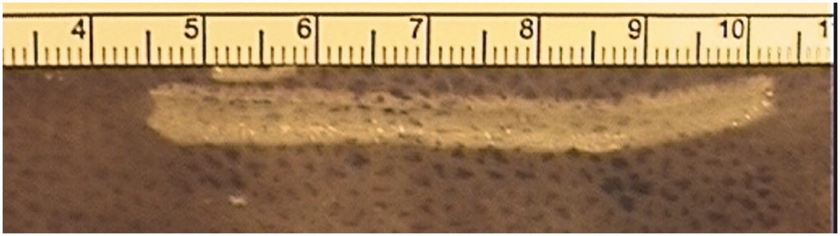
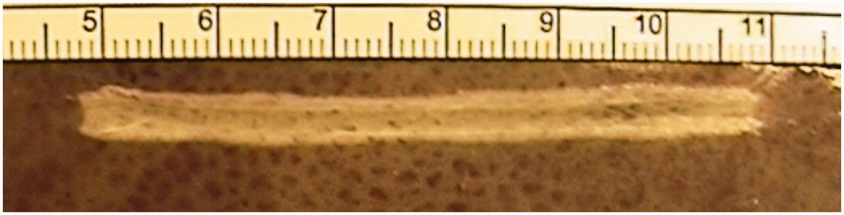
The discontinuous method of pullback (6 s at 6 W, then pullback 0.5 mm and repeat for the length of vein to be treated) giving an LEED of 72 J/cm) (Figure 9) produced a mean thermal spread of 1.66 mm, which was significantly higher than any other setting tested (p < 0.05 against all other settings).
Treatment settings of 6 W with a discontinuous pullback of 12 s/cm performed as 6 s stationary, withdraw 0.5 cm then repeated (LEED = 72 J/cm). This discontinuous pullback showed the highest mean thermal spread and was easiest for the operator to perform reliably and repeatedly.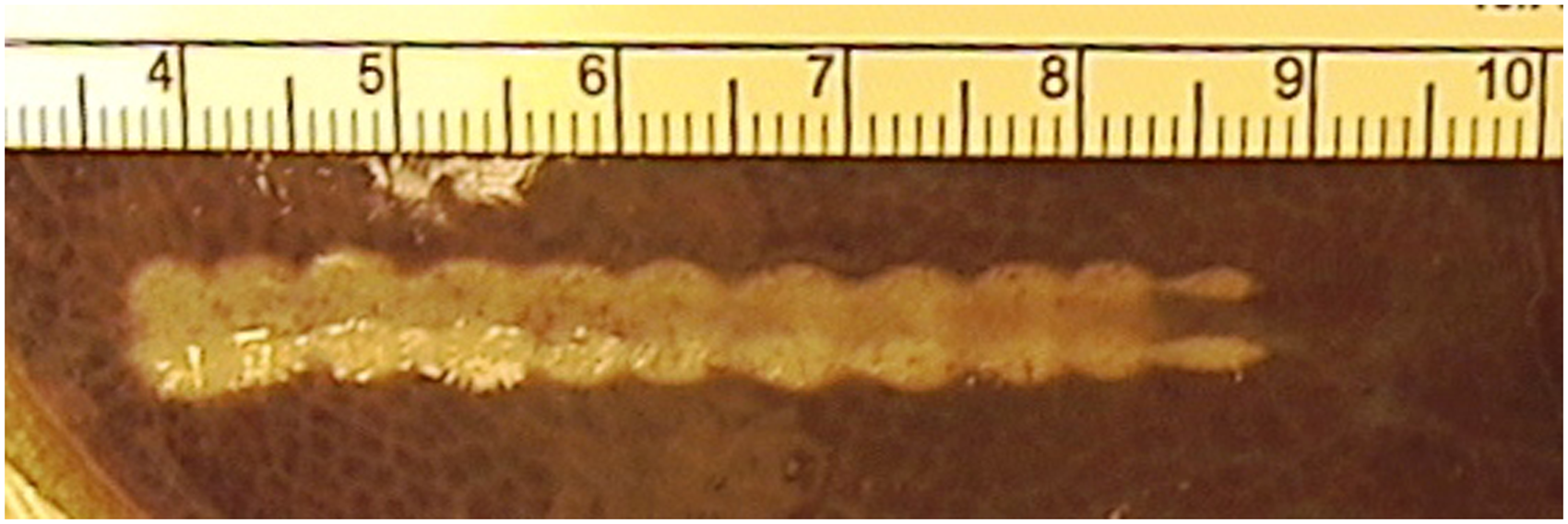
Discussion
Any in vitro model will have differences from the in vivo situation. Without doubt, the fact that the catheter is pressed against the glass shows that it is not surrounded by biological tissue as it would be when in the vein during an actual treatment. However, this model enables thermal spread to be easily observed and measured and so, as this model appears to predict the effects seen in the ex vivo GSV (see below), it would appear to be adequate to derive the conclusions reached in this article.
In vivo, the truncal vein being treated is surrounded by tumescence. This separates the vein from the surrounding sub-cutaneous fat and when combined with a “head-down” position, causes the vein to contracted around the catheter, virtually exsanguinating the vein and leaving no significant blood within the lumen. The vein wall itself is not infiltrated with tumescence. Hence the normal saline spread liberally over this model will mimic the presence of tumescence around the catheter.
Porcine liver was chosen for our in vitro study for four reasons. First, there is a precedent for using porcine liver to investigate the thermal effects of radiofrequency on biological tissue. 14 Second, the cells density in porcine liver is similar to that in GSV. Third, porcine liver is a dark colour and when treated with thermoablation, the ablated tissue turns a light colour. The tissue turning lighter is due to the thermal changes in the tissue itself, representing a denaturation of the protein in the cells, which would correspond to cellular damage and probable death in living tissue. This contrast of colour makes measurements easy. Finally, we have performed a correlation study showing that there is a close correlation between results found using the assumptions made in about thermal spread measured in this model and that found by the same treatment in explanted GSVs. That article is also being submitted for peer review for consideration of publication. 13
Doctors using RFiTT and the recommended treatment levels of 18–25 W often report at conferences that treatments are interrupted by high impedance cut outs and the need to remove the device to clean carbonised tissue from the electrodes (often called “coagulum”).
We have shown that the original recommendation and previously prescribed techniques of 20 or 18 W at 1 s/cm (LEED = 18 or 20 J/cm, respectively) give very poor thermal spread, which would not cause transmural death in all GSVs. Therefore, we would expect a proportion of veins treated with this technique to show reopening of the treated veins in time.
These views are supported in the written literature with studies reporting the outcomes from using these settings showing some failures, with improved results being found if the pullback is slowed from 1.0 to over 1.4 s/cm.7,9 However, high levels of successful ablation are reported only when the poor results from “inexperienced” doctors (fewer than 20 cases) were excluded. 9
Presentations at conferences by “experienced doctors” about the technique of performing RFiTT often include recommendations to treat with multiple passes to ensure closure and to reduce the chance of high impedance cut outs and the need to remove the device for cleaning, and a recent publication has echoed this advice. 11
The carbonisation of the tissue as described in this in vitro model probably corresponds to two clinical problems. The first is the sticking of the catheter and the formation of coagulum that needs to be removed 10 and the second is that for successful thermoablation, the vein wall only needs to be heated until the majority of the cells in the walls are coagulated and dead. 15 Carbonisation either means excessive energy has been used, or more likely that there has been inadequate thermal spread in the wall with excessive heat damage causing carbonisation of the innermost layers and leaving the outer layers of the wall alive, leaving the risk of subsequent recannalisation. 16
We have shown that the higher power levels of 18 and 20 W tend to burn the tissue in contact with the device, causing carbonisation and sticking of the device, necessitating a fast pullback that reduces thermal spread in the tissues. The 1 s/cm pullback at these powers resulted in low LEEDs and poor thermal spread in the tissue, falling far short of our target 0.65 mm in this model. When we tried to increase the LEED towards 60 J/cm while using the higher power level of 18 or 20 W by utilizing a slower pullback, we found carbonisation of the tissue and sticking of the device, although thermal spread within the tissue did increase and pass our 0.65 mm target.
To maintain the high LEED of >60 J/cm but to overcome the carbonisation and sticking to the tissue, we have shown that by reducing the power first to 12 W and then further to 6 W, we can achieve our target thermal spread with no tissue carbonisation or device sticking at all. Indeed, the lowest power (6 W) with the slowest pullback (12 s/cm) produced the best thermal spread of all settings tested and no tissue carbonisation or device sticking at all and hence no high impedance cut outs during the treatments.
However, although it is necessary to slow the pullback speed with the lower powers to maintain the LEED, this slow device withdrawal is not without its problems. The slow, continuous 12 s/cm pullback necessary to achieve LEEDs of 72 J/cm without carbonisation is difficult for the operator to perform accurately and repeatedly. It became clear to us that when pulling back at 12 s/cm, a small deviation in pullback rate could cause a large disparity in the results, decreasing the potential effectiveness of the procedure. Hence we developed a staged discontinuous pullback of 0.5 cm every 6 s, which we found allowed the operator to achieve far more reproducible results in terms of LEED.
The reason that 0.5 cm was selected as a pullback length rather than 1.0 cm, which would have been easier, was because of the pattern of heat effect generated by the treatment tip of the RFiTT device. When observing the use of the device in the porcine liver model under glass, it was clear that the heat was generated in the tissue between the two electrodes, not directly at the tip or on the electrodes themselves. Simple observation of the shape of the thermal spread within the tissue showed us that when using 0.5 cm treatment lengths, the areas of thermally treated tissue overlapped each other. When using 1.0 cm treatment lengths, the overlap between the treatment areas was insufficient, leading to areas between the treatment points where the thermal spread did not meet the minimum target thermal spread of 0.65 mm. We felt that this could represent a potential clinical failure of treatment and so was rejected in favour of the 0.5 cm treatment lengths that did not leave any areas under the target thermal spread.
For this study we have used an in vitro model rather than an in vivo model. Therefore, findings, although clear in the porcine liver model, will need to be confirmed in human GSV and also in clinical practice. These studies have been now been performed and have been submitted for consideration for publication
In conclusion, using an in vitro porcine liver model, we have shown that when using RFiTT, a low power setting of 6 W combined with a slow pullback of 12 s/cm produces a larger thermal spread than a high power setting and rapid pullback. We have confirmed that an LEED of >60 J/cm is needed to achieve a thermal spread >0.65 mm, which we chose as our target to represent transmural thermal death in the GSVs with the thickest walls. We have also found that slow pullback necessary to achieve LEEDs of 72 J/cm is difficult for the operator to perform consistently. We have suggested a discontinuous pullback technique of 6 s treatment at 6 W with the device stationary, followed by a 0.5 cm withdrawal and then a repeat of this cycle until the whole target length of tissue had been treated, which we showed to be easy to perform and reproduce.
Footnotes
Acknowledgements
The authors would like to thank Simon Ford of Olympus, who started experimenting with different power levels in an in vitro model and shared his early results with us. It was Simon Ford’s work that gave us the clue to developing our method of obtaining an LEED of 72 J/cm for optimal treatment of the veins. We would also like to thank Mr Barrie Price of The Whiteley Clinic for his suggestion of using the pixel to mm conversion to measure the thermal spread.
Conflict of interest
The authors declare there is no conflict of interest
Funding
Whiteley Clinic Research Grant.