



Abstract
The penetration of large-scale wind power generators to the grid has resulted in an increasing focus on the study on their fault ride through issue that is becoming imminent. The doubly fed induction generator-based wind turbine is still one of the most frequently adopted wind generation units in the market of the installed wind power worldwide due to its good behavior during normal grid conditions. However, due to the sensitivity of doubly fed induction generator to power disturbances, especially to voltage sags, the transient characteristic improvement of doubly fed induction generator during fault, thus meeting the fault ride through requirements, has become a problem of particular interest to wind turbine manufacturers. So, in this article, a comprehensive comparative study on the fault ride through techniques for doubly fed induction generator wind turbine is provided based to three broad subcategories: control algorithms, additional hardware circuit, and combined approaches. Furthermore, a discussion on the different characteristics of the fault ride through capability of these methods has been made, and a case study has been carried out to show the performance of different schemes. Finally, the article suggests a likely future outlook for the fault ride through technique for doubly fed induction generator wind turbines.
Introduction
Wind power generation plays an important role in the world energy markets due to the rapid growth of their installed capacity over the past 20 years (Li and Shi, 2010). In comparison with the fixed speed generators, most grid-connected wind turbines (WTs) operate at variable speed due to the benefits of variable speed operation, which is presented in detail in Boutoubat et al. (2013). For example, variable speed WT can reduce mechanical stresses, thus increasing the lifetime of the turbine, and it also helps to dynamically compensate for pulsations in torque and power and as a result the power output can be smoothed. In addition, the maximization of the wind energy conversion efficiency can be realized by adjusting its rotational speed to an optimal point for each given wind speed (Ling et al., 2012b).
There are different kinds of wind power to obtain variable speed; however, the doubly fed induction generator (DFIG)-based WT is now a preferred choice for installation. This is mainly because: (1) the rated power of its converter is set to about 25% of the machine rating power and as a result its equipment cost can be reduced (Muller et al., 2002), and (2) the decoupled control of its active and reactive power can be carried out using the classical vector method (Boutoubat et al., 2013; Ling et al., 2012b).
However, one of the main concerns of the DFIG WT is its poor performance during grid voltage sags, which can result from the external short-circuit failures. The reasons are as follows: (1) their sensitivity to grid fault, especially to voltage dips, which results due to the direct interconnection of the stator windings of DFIG to power grid (Dittrich and Stoev, 2005), and (2) the existence of a four-quadrant power converter of partly rated power (Gao et al., 2009). When a DFIG experiences an abrupt drop in grid voltage, the maximum values of the over-currents in the rotor windings of DFIG will reach about 5–10 times the nominal values (Ling and Cai, 2013; Yang et al., 2008). The over-currents will damage the ride-side converter (RSC), if no protective devices are taken. If the currents are tried to be limited by current control on the RSC, the voltages at the output terminals of RSC will increase and might exceed their limit and thereby also damage the converter (Morren and De Haan, 2005).
In the past, the focus on the protection of DFIG-based WTs was to protect the turbines themselves in grid voltage fault events. The past practice was that the WT generators were asked to be disconnected from the fault grid when the terminal voltages fell below 70–80% (Zhan and Barker, 2006). However, at present, as large-scale WTs are connected to the power system, disconnecting a majority of wind energy generators from the grid during voltage dips is not allowed. The reason is that this could seriously affect the stable and secure operation of the power system, and even further lead to the collapse of the power system (Hansen et al., 2007).
According to the above analysis, the high penetration of WTs will have a serious negative impact on the grid stability. In order to guarantee the stable work of the power system, the network operators in some countries, such as Germany, have revised the grid codes and added the specific requirements for WTs (Erlich et al., 2006; Hansen et al., 2007); in other words, the premise of a WT that may be linked to the power grid is that it must fulfill the new grid requirements. Faced with such facts, important research activity is being made by both industry and academia regarding the ability of different WT systems to meet the new requirements. Among these new requirements, those regarding the capability of WT generation units to ride through the voltage fault have attracted widespread attention lately, especially for DFIG-based WTs. In recent years, a variety of published articles have showed various methods about the improvement of the behavior of DFIG-based WT in case of grid voltage dips, thus fulfilling the fault ride through (FRT) requirements set by the new grid codes (García-Gracia et al., 2009).
So, in the article, first, in the section “Grid codes,” a brief review of new grid technical requirements is provided. Then, in the section “DFIG-based WT configuration,” DFIG WTs’ configuration is summarized. A comprehensive comparison of the FRT technique for DFIG WTs in recent years is presented in detail based on three broad categories: control algorithms, additional hardware circuit, and combined FRT schemes in section “FRT schemes of DFIG-based WT”. A case study has been carried out in section “Case study”. Finally, the article is closed by a conclusion in section “Conclusion.”
Grid codes
In order to deal with the challenges on the stable and secure operation of power system brought about by the large penetration of WTs into the network, grid codes have been revised. Although the grid codes in scope and specific details are different in different countries, the typical grid codes should consist of the following areas.
Voltage control
The range of variation in voltage in most of the utilities is generally set to ±5% of the nominal voltage, but it also has a relationship with the voltage grade (Kyaw and Ramachandaramurthy, 2011). The grid codes require WTs to continuously operate within the voltage range and even the extended range that is generally set between 0.9 and 1.1 pu in most utilities (Kyaw and Ramachandaramurthy, 2011; Mohsenia and Islamb, 2012). The grid codes also require that wind farms could control the output of reactive power, thus offering voltage support facility to the network operator (Mohsenia and Islamb, 2012). In general, the power factor is allowed to vary from −0.9 (leading) to +0.9 (lagging) (Kyaw and Ramachandaramurthy, 2011).
Frequency and power control
Due to the imbalance between power production and consumption, power system frequency nature is continuously changing, but the amount of change is usually small. In Australia, the WTs should be able to work continuously from 49.5 to 50.5 Hz, operate within the 49–51 Hz scope for 10 min, between 48 and 51 Hz for 2 min, and within the worst 50–60 Hz for 9 s. The WTs should be able to carry out the limited active power control in response to the small variations in frequency. So, the system operator can be provided with the restricted frequency regulation service. The maximum rate of change in active power is also imposed on WTs (Kyaw and Ramachandaramurthy, 2011; Mohsenia and Islamb, 2012).
FRT capability
FRT requirements were first proposed by Erlich et al. (2006) and shortly were adopted by many utilities in the world. During the occurrence of grid voltage faults, including both voltage sags and voltage swells, WTs should be able to keep being connected to the grid for a given time. The main aim is basically to ensure, as far as possible, a reduction in the loss of power generation before the clearance of the fault. Disconnecting a WT generator too quickly could damage the stable and secure operation of power system, especially for large-scale wind farms. In addition, some grid codes require that the WTs should be able to support grid voltage recovery during the fault by supplying reactive power to the grid. So, this will help WTs return to normal operation after the clearance of the fault. Topical low-voltage ride through (LVRT) requirements are shown in Figure 1. According to the figure, WTs cannot disconnect the grid for a zero voltage with the duration of less than 150 ms. The duration strongly depends on the depth of voltage fault, that is, a deeper voltage drop means a shorter duration.
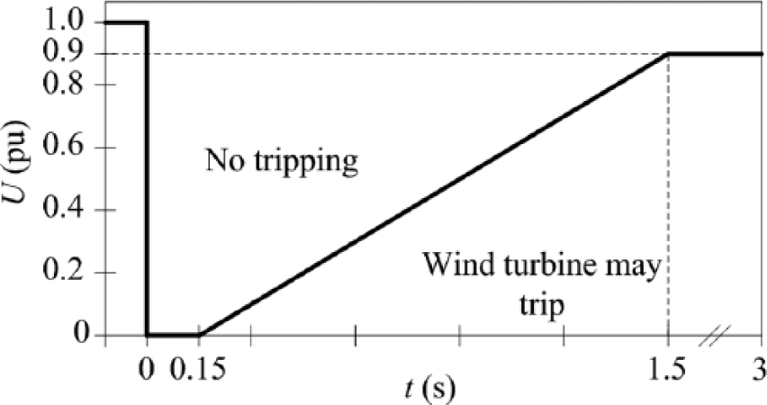
Topical LVRT requirements—Germany.
In addition, some countries’ grid codes also require that WTs should be able to ride through the high-voltage fault. For example, the German Grid Codes require WTs to keep being connected to the grid for voltage swell of 1.2 pu with the duration of 100 ms (Mohsenia and Islamb, 2012).
DFIG-based WT configuration
In DFIG-based WT, the stator winding of DFIG and the grid is directly connected. The turbine control is performed using the back-to-back power converters that consist of the RSC, the grid side converter (GSC), and a direct current (DC)-link capacitor, as shown in Figure 2. To maintain a constant, DC-link voltages can be carried out by the control of GSC, while the decoupled control of the stator powers of the generators can be carried out by RSC (Hansen et al., 2006; Zamanifar et al., 2014). Pitch control system can cut back the extraction of wind power by increasing the pitch angle, and then the rotor speed is controlled to normal value range.
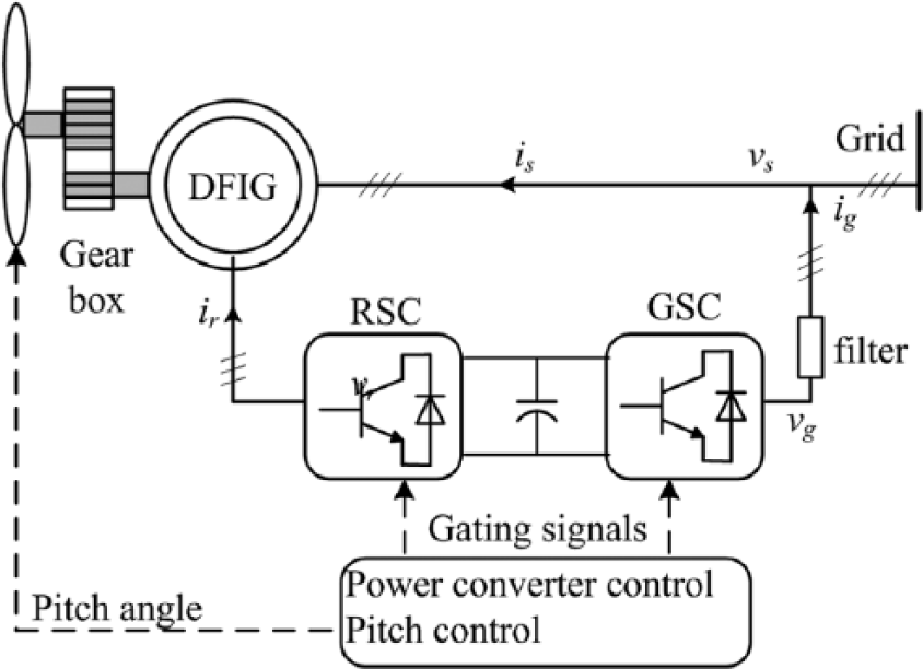
Structure of a DFIG-based WT.
FRT schemes of DFIG-based WT
In order to meet the FRT requirement of WTs, a number of FRT schemes for DFIG have recently been proposed in the literature. After in-depth analysis, we put these schemes into three broad subcategories as following.
FRT schemes based on control algorithms
In such control schemes, the focus is put on the design of specific control strategies for RSC and GSC, more for RSC. In general, any auxiliary external hardware devices are not used.
Conventional vector control (VC) for the DFIG-based WT system can gain good control performance only under ideal grid voltage conditions. When the grid voltages fail, the prerequisites are destroyed, and as a result the control performance will deteriorate. If the voltage fault is severe, the DFIG-based WT system will not be able to ride through the fault. So, to meet the FRT requirements, in Hu et al. (2006), in the rotor current control, the stator excitation current dynamic terms are real-time introduced to the feed-forward voltage compensation terms, and so, the dynamic responses of DFIG system are improved under the not-serious grid fault. Based on the same considerations, in Liang et al. (2010), the stator voltage dynamics are injected into the feed-forward voltage compensation terms of the RSC current controller and this is named after dynamic current feed-forward control. When a voltage fault appears, these transient terms can result in minimum peak value of transient rotor fault current.
The main difficulty for the ride through of DFIG is how to deal with back electromotive force in the rotor. It is well known that it depends on the damped oscillating component in stator flux linkage and rotor speed, that is, how to make the stator flux attenuate fast, thereby reducing their effect on the transients of rotor current is the focus. So, in Xiang et al. (2006), the influence of stator flux may be weakened via the injection of suitable rotor current to the rotor winding. However, this is a complicated method and it depends largely on the assessment of certain parameters. To reduce the complexity of the control, a flux tracking method for FRT is presented in Xiao et al. (2011), where the changing stator flux is tracked through controlling the RSC when the voltage dip occurs. In Mendes et al. (2011), a proposed simple solution, which is named after the magnetizing current control, can also increase the flux damping. This method does not need the voltage fault detection device for the control aim, and even can control the reactive power, and also can improve the transient performances of the WT system during balanced voltage dips, but it is at the cost of high rotor voltages. Another flux damping strategy is proposed in Rodriguez et al. (2005). In the strategy, first, the oscillatory component of stator flux can be extracted and as a result we gain a damping current that proportionally depends on the nature flux, and then the current is superposed to the output of reactive power controller for RSC. The strategy is further developed in Lopez et al. (2009) and Rahimi and Parniani (2010a). The active component of the transient current is also introduced to the output of active power controller for RSC. The strategy can enhance the FRT capability of the system during moderate voltage sags, which strongly depends on the control gain. But the difference is that the idea of conversion between the fault control mode and the normal control mode has also been applied in Rahimi and Parniani (2010a), that is, the fault control mode is introduced into the existing control system. Its main features include the following: (1) it is independent of the system’s normal operation, and (2) the need for additional fault detection device. Different flux damping control schemes in Xiang et al. (2006), Xiao et al. (2011), Mendes et al. (2011), Rodriguez et al. (2005), Lopez et al. (2009), and Rahimi and Parniani (2010a) can be seen in Figure 3 and it is found that Lopez et al. (2009), Mendes et al. (2011), Rahimi and Parniani (2010a), Rodriguez et al. (2005), Xiang et al. (2006), and Xiao et al. (2011) have the disadvantage of the necessity of flux estimation.
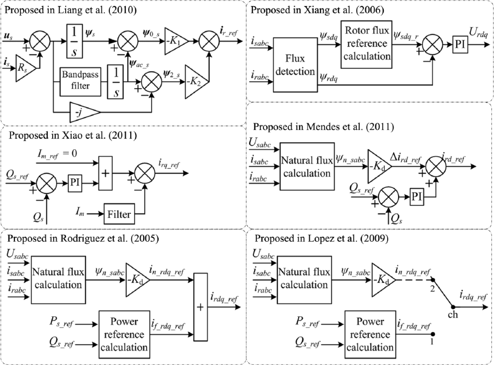
Different flux damping control schemes.
The idea of mode conversion above is also applied in Lima et al. (2008, 2010) and Wessels and Fuchs (2010). In Lima et al. (2008, 2010), the stator currents are measured and act as the reference value of the RSC current controller during the fault. As shown in Lima et al. (2008, 2010), a DFIG-based WT can be well controlled even if under serious faults without auxiliary hardware circuits. But the limitation of this method is that rotor voltage, RSC rating and speed are not considered. In Wessels and Fuchs (2010), rotor voltage and RSC rating have been considered, but the system speed is still not considered.
Moreover, as presented in Yao et al. (2008), an improved control method for GSC based on the instantaneous power feedback can improve the stability of DC-link voltage. However, it can improve the stability of DC-link voltage only during a not-serious grid voltage dip.
More advanced control strategy is also used to try to control DFIG-based WTs and to help them ride through voltage faults. For example, the use of nonlinear control for RSC or GSC is proposed in Rahimi and Parniani (2010a, 2010b), Soares et al. (2010), and Ling (2014), respectively. This is because the dynamics of DFIG electrical and DC-link is nonlinear, and the classical linear control strategy cannot work well in severe voltage dips. In Rathi and Mohan (2005), the authors designed a novel control strategy utilizing H∞ technique and µ-analysis, and in the design process different adverse conditions are considered as far as possible. However, this program proved to be complex and requires a long computation time. Also, sliding mode control (Shang and Hu, 2012), high-order sliding mode control (Beltran et al., 2009), and internal model control (Campos-Gaona et al., 2013; Morren and De Haan, 2005) are applied to help DFIG-based WTs ride through voltage faults.
The articles discussed above show the results for the symmetrical voltage dips, but most dips in power system are unbalanced. In addition to causing possible over-current, imbalance voltage drop also leads to a double-frequency oscillation in electric power and electromagnetic torque, which can fatigue and further destroy the turbine mechanical unit, such as the gearbox (Leon et al., 2012). In recent years, several works have introduced some schemes to address these problems. After in-depth analysis, we put them into the following three categories:
Approach based on dual VC (Gomis-Bellmunt et al., 2008; Hu et al., 2010; Xu and Wang, 2007). In this method, two dq reference frames are necessary, in which the positive- and negative-sequence currents may be controlled independently and so four current control loops are required. As a result, the complexity of the system control is increased.
Approach with proportional–integral plus resonant (PI-R) regulator. Positive- and negative-sequence currents can be regulated using PI-R regulator under dq synchronous rotating coordinate system, which can track both constant and sinusoidal reference signals without steady-state error (Hu and He, 2011; Leon et al., 2012), and it is also applied in a αβ stationary reference frame to control the vibrations in power and torque (Luna et al., 2009).
Improved direct power control (DPC) or direct torque control (DTC) approach (Abad et al., 2010; Hu and Yuan, 2012; Nian et al., 2011; Santos-Martin et al., 2008, 2009; Shang and Hu, 2012). In such scheme, the common feature is the need to recalculate the appropriate power control commands to weaken the torque vibration and improve the power oscillation. However, in general, the power control references can be calculated using the positive- and negative-sequence components, which are separated from active and reactive power outputs (Santos-Martin et al., 2008, 2009; Shang and Hu, 2012; Nian et al., 2011) or obtained indirectly utilizing active power and estimated torque (Abad et al., 2010). Sliding-mode control (Shang and Hu, 2012) and PI-R controller (Nian et al., 2011) are also introduced into DPC control to help DFIG enhance its performances during unsymmetrical voltage faults.
FRT schemes based on additional hardware circuit
When a DFIG experiences a severe voltage dip, the limited capability of the RSC cannot provide enough control voltage and so rotor fault currents cannot be well limited. Hence, for this situation, an additional hardware circuit is required to help DFIG improve its FRT capability. At present, there are a variety of different circuit topologies, which will be reviewed in detail as follows.
Crowbar
Among the different FRT solutions, the most preferred one implemented by the manufacturer is the crowbar (CB), which consists of a set of bypass resistors. Figure 4 shows that the CB is connected to the rotor winding by means of a pair of anti-parallel thyristors, called passive CB. If the anti-parallel thyristors are replaced with insulated-gate bipolar transistor (IGBT) switches, the CB is called active CB. When the voltage fault occurs, the CB should be activated; at the same time, RSC is bypassed and the rotor over-current flows through the resistors instead of the converter. The passive CB circuits can protect the converter. However, in contrast with the passive CB, the active CB largely enhances its operation and can faster eliminate the rotor transients (Erlich et al., 2007a; Hansen and Michalke, 2007; Kalantarian and Heydari, 2011; Kasem et al., 2008; Ling et al., 2012a; Lohde et al., 2007; Meegahapola et al., 2010; Morren and De Haan, 2005, 2007; Pannell et al., 2010; Peng et al., 2009; Peng and Yikang, 2007; Wang et al., 2012; Yang et al., 2010; Zhang et al., 2010).
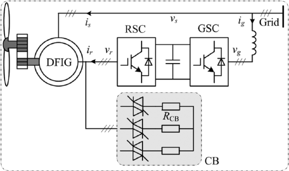
Schematic diagram of crowbar application.
In recent years, much attention has been received by the CB, where the research is focused on as following:
Determination of the CB resistance values (Hansen and Michalke, 2007; Morren and De Haan, 2007; Yang et al., 2010; Zhang et al., 2010), and their optimization or effect on the DFIG WTs (Hansen and Michalke, 2007; Kalantarian and Heydari, 2011; Lohde et al., 2007; Meegahapola et al., 2010; Pannell et al., 2010; Wang et al., 2012; Xiao et al., 2011).
Control of the CB can provide the switching strategies to trigger the CB depending on different standards by the comparator, such as the DC-link over-voltage or rotor over-current (Kasem et al., 2008; Ling et al., 2012a; Yang et al., 2010). However, to avoid the work of the CB as far as possible, many ways have been proposed, such as a pulse-width modulation (PWM) control of the CB (Rodriguez et al., 2005), a hysteresis control of the CB (Peng et al., 2009), and a control scheme based on edge triggered D-type flip-flop (Peng and Yikang, 2007).
However, the main disadvantage of the CB is the runaway problem of the DFIG under voltage faults. This problem will lead to the increase in reactive power consumption and system speed. Therefore, the alternative implementation of the CB is proposed in Rahimi and Parniani (2010a), Gao et al. (2009), and Yang et al. (2010), where the CB is inserted between the rotor windings and the RSC, named after rotor series CB (RS-CB) (see Figure 5), while in Rahimi and Parniani (2010a), Okedu et al. (2011), and Esandi et al. (2009), the CB is inserted between the stator and the grid, named after stator CB (S-CB) (see Figure 6). Their operations are different from the CB. Under the ideal network conditions, the currents flow through the bypass switches by turning the switches on; under fault conditions, the fault currents are forced to flow through the resistances by turning the switches off. Both can enable the DFIG WTs to ride through the severe voltage faults. But the performance of the S-CB method is better than that of the RS-CB approach (Rahimi and Parniani, 2010a). This is because the damping of stator transient reduced by the increase in the resistance in the rotor. But the additional converter losses of the S-CB produced during normal operation are far higher than that of RS-CB because the power rating of RSC is low (Yang et al., 2010).
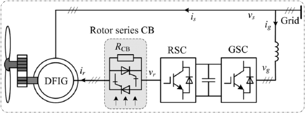
Schematic diagram of rotor series crowbar application in DFIG WT.
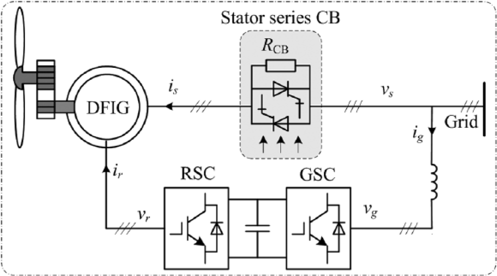
One of the stator series crowbar applications based on DFIG WT.
Another main disadvantage of S-CB is the higher number of components used. An alternative scheme to reduce the elements needed is proposed in Esandi et al. (2009). As represented in Figure 7, the neutral stator is replaced with a diode-bridge rectifier feeding a resistor in parallel with a switch. The equivalent condition of the configurations of Figures 6 and 7 is that the damping resistant should meet the following equation

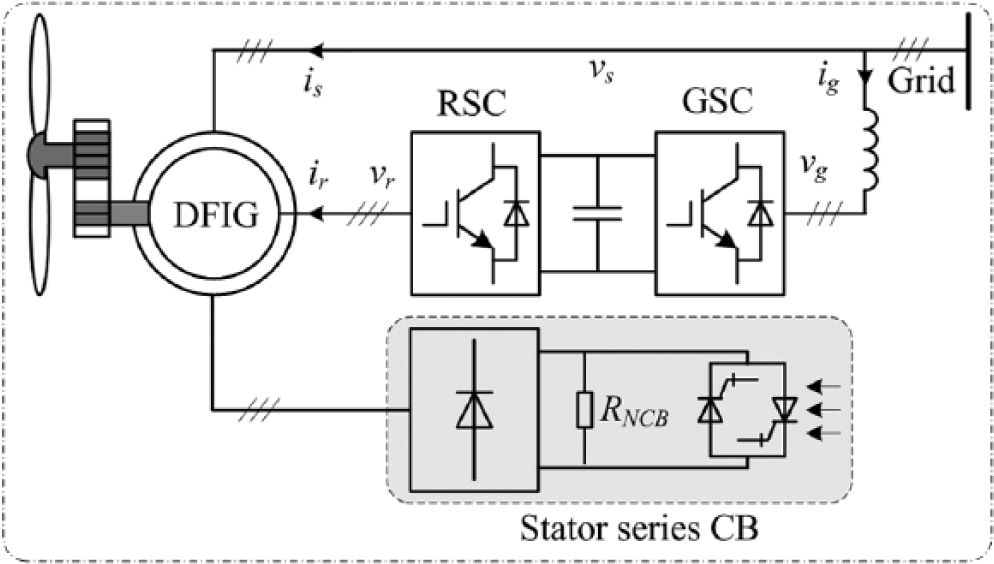
Another application of stator series crowbar in DFIG WT.
Fault current limiter
Fault current limiter (FCL) is mainly used to limit the peak values of fault currents to an acceptable range by quickly inserting a series inductor in the failure path. There are different types of FCL topology for selection (Verma, 2009). In Fazli and Talebi (2010), a type of FCL, which is called a static current limiter (SCL), is applied to suppress the rotor fault currents of DFIG. As shown in Figure 8, this FCL, which includes a switch, an inductor, and an arrester, is inserted between the rotor windings and the RSC. Another different application of FCL is that the selected type of FCL is placed between DFIG and infinite bus (Falahzadeh and Heydari, 2012; Park et al., 2010). This FCL is based on superconductor resistance and as a result is called a superconducting fault current limiter (SFCL), which can fast and effectively reduce the level of fault current.
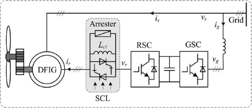
Schematic diagram of fault current limiter-SCL.
Dynamic voltage restorer
The dynamic voltage restorer (DVR) can fast and effectively compensate the faulty voltage, and as a result eliminate most grid voltage sags, even most voltage swells. Different configurations of DVR have been presented and compared in Nielsen and Blaabjerg (2005). A typical DVR topology for DFIG WTs can be seen in Figure 9 (Wessels and Fuchs, 2009), where it is found that the DVR actually acts as a voltage source converter and is inserted between the DFIG and infinite bus by an injection transformer. In addition, it also includes output filter, energy storage unit, bypass switch, and so on. But in Wessels and Fuchs (2009), only symmetrical voltage sag has been studied. The asymmetrical grid faults are further investigated in Ibrahim et al. (2011) and Wessels et al. (2011). But DVR topology adopted in Ibrahim et al. (2011) and Wessels et al. (2011) is different, and in Wessels et al. (2011), the topology is more complex and reactive power is not considered. However, the performance of the DVR also attracts people’s attention and is determined by its controller. In Ibrahim et al. (2011), in order to compensate the unbalanced voltage dips, PI-R voltage controller in the stationary frame is adopted, while dual VC base PI controller is used in Wessels et al. (2011). The two methods are further investigated and compared in Jin et al. (2012). Both control methods have good transient and steady-state responses. However, obviously, the former method is simpler. The main reason is that the complex analysis of positive- and negative-sequence components is not required in the stationary frame.
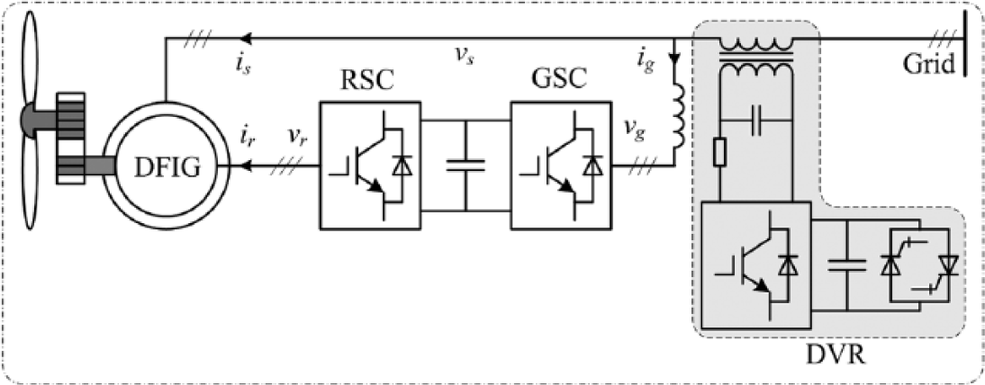
Schematic diagram of dynamic voltage restorer.
Overall, the complexity in the DFIG system can be reduced by the use of the FRT method based on DVR. But the high cost and complexity of DVR are its main drawbacks. Based on this consideration, a DVR is very suitable for protecting the WT that has been fixed but cannot ride through the voltage faults (Wessels et al., 2011).
Series GSC
The DVR mentioned above can be simplified to the series grid voltage converter (SGVC), which can act as a DVR and isolate the DFIG WTs from the faulty grid. As shown in Figure 10, an application of the SGVC for DFIG WT is implemented in Zhan and Barker (2006), where the additional converter can not only act as a DVR but also together with other two existing converters will get more flexible control when integrated into the network under the new grid codes. Two other alternative implementations of the SGVC are presented in Flannery and Venkataramanan (2007). As shown in Figure 11, the SGVC can be located in the neutral point of the stator windings, and it can also be placed between the stator winding and infinite bus by a series transformer, as shown in Figure 12. Their circuit configurations are similar. The difference between the two approaches is whether an injection transformer is used. If a transformer is used, the determination of the voltage rating of the SGVC will not depend on the specific DFIG stator voltage for voltage injection. Both of them can provide DFIG WTs with good zero voltage ride through capability. Asymmetrical voltage sags have been investigated in Liao et al. (2011), Flannery and Venkataramanan (2009), and Massing and Pinheiro (2008) based on the SGVC, as shown in Figure 11. But the injection transformer saturation is not considered. In Massing and Pinheiro (2008), the H∞ controller is adopted.
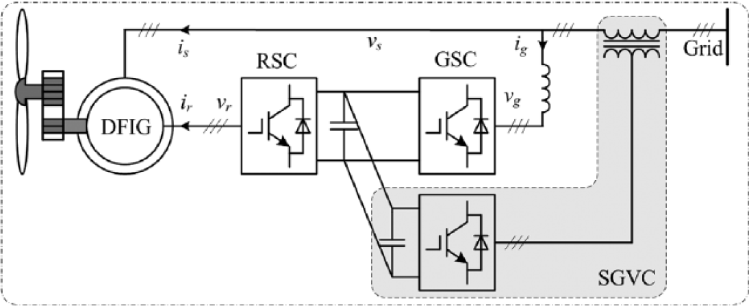
The first series grid voltage converter application based on a DFIG-based WT.
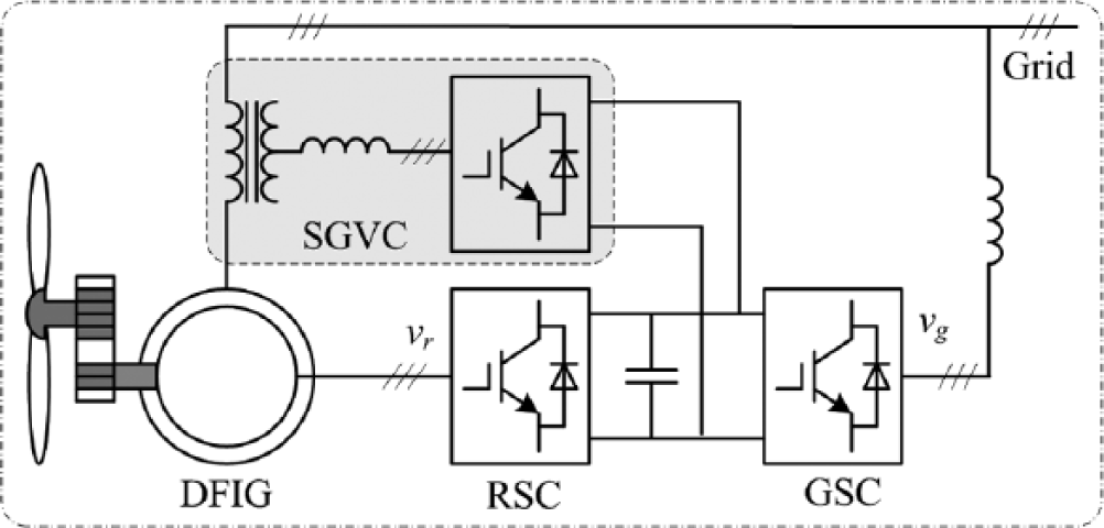
Another series grid voltage converter application in a DFIG-based WT.
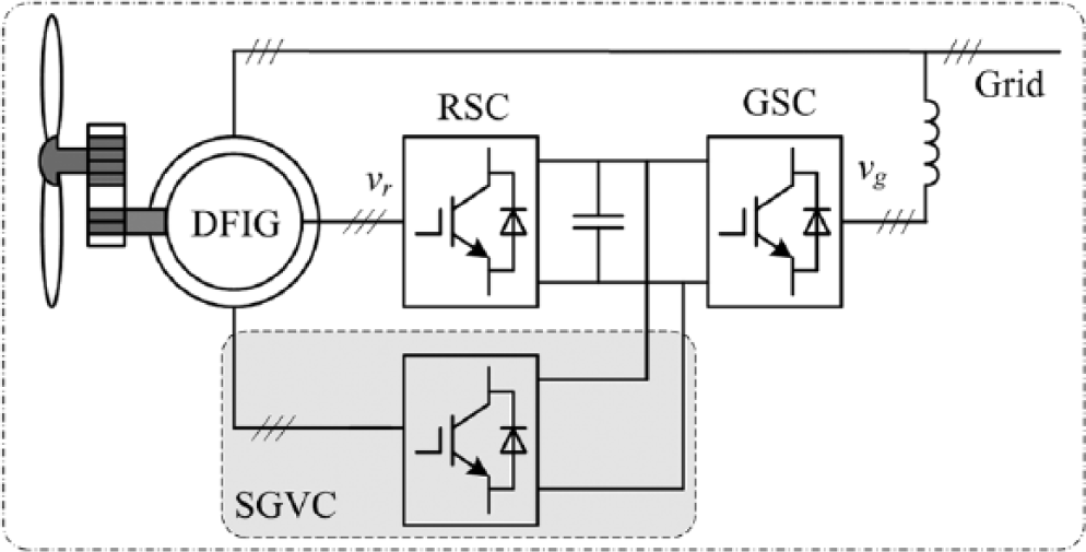
Last series grid voltage converter application in a DFIG-based WT.
Dynamic reactive compensation
Dynamic reactive compensation, as a controllable source of reactive power, is a robust and well-developed technology that could be applied to regulate voltage and reactive power, thus improving power grid voltage stability. Therefore, the dynamic reactive compensator (DRC) can also be used to enhance the voltage stability of the large wind-based generation farm during power grid disturbances. A static VAR compensator (SVC), one of the DRCs, is proposed to help wind-based generation farm ride through the grid voltage faults (Akhmatov and Søbrink, 2004; Boussea et al., 2006; Boynuegri et al., 2012; Dermentzogloua and Karlis, 2011). Another of the DRCs, static synchronous compensator (STATCOM), can also be used to help wind-based generation farm ride through the grid voltage faults (Abdou et al., 2012; Akhmatov and Søbrink, 2006; Hossain et al., 2011; Molinas et al., 2008; Qiao et al., 2009; Ramirez et al., 2012; Ronner et al., 2009). The differences between the SVC and the STATCOM are as follows:
The SVC, based on thyristor-controlled reactor (TCR), is connected in parallel between the grid and a wind park at the point of common coupling (PCC), as shown in Figure 13(a). The SVC cannot generate voltage and thus can only provide the dynamic voltage control within a given range of grid voltage. When the grid voltage becomes extremely low, the SVC is blocked and so the FRT of wind farms fails.
The STATCOM is based on voltage-sourced converter (VSC). Figure 13(b) shows its connection to the grid. The STATCOM is able to act as an alternating current (AC) voltage source and thereby reactive power can be controlled from totally inductive to totally capacitive situations and its control performance does not depend on the grid voltage. Hence, even if a wind farm is subjected to a large voltage sag, the wind parks also can successfully ride through the fault. As shown in Molinas et al. (2008), based on wind farms with cage generators, the LVRT capability of the STATCOM is better than that of the SVC if their power ratings are set the same. But, compared to the STATCOM, the SVC is usually considered to be a cheaper and simpler solution.
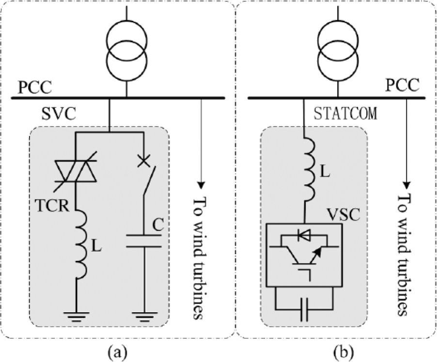
Implementations of an SVC or a STATCOM at a wind-based generation farm.
DC chopper and energy storage system
As shown in Figure 14, a chopper circuit can be connected in parallel with the DC-link capacitor, and so it can suppress the over-voltage of the power electronic converter DC bus. The over-voltage is mainly caused by the unbalanced power flow in the back-to-back converter when grid voltage faults occur (Abbey et al., 2008; Erlich et al., 2007b; Liang et al., 2010; Okedu et al., 2011; Yang et al., 2008, 2010). An alternative, energy storage system (ESS), can be used to manage the excess energy during the voltage disturbance (Abbey et al., 2008; Abbey and Joos, 2005, 2007; Li and Zhang, 2010; Sarrias et al., 2012) as shown in Figure 15. Both methods can protect the DC bus from over-voltage and avoid the problem of the conversion between the different modes of operation, but they cannot suppress well the fault currents that flow into the RSC. Hence, they require a higher current rating of RSC, which will lead to an increase in cost. The difference between them is that the extra energy is dissipated by the resistance in DC chopper circuit while stored in ESS method. As soon as the grid voltage returns to nominal, the stored energy can be exported to the grid. Note that various ESSs such as batteries (Abbey and Joos, 2005; Li and Zhang, 2010; Sarrias et al., 2012) and super-capacitors (Abbey and Joos, 2005, 2007) can be selected for short-term power exchange.
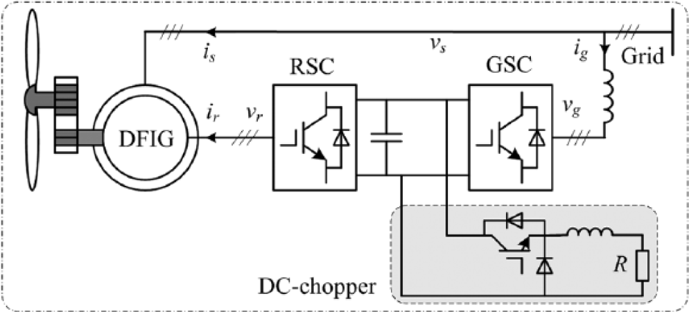
DFIG-based WT with energy discharge circuit: DC chopper.
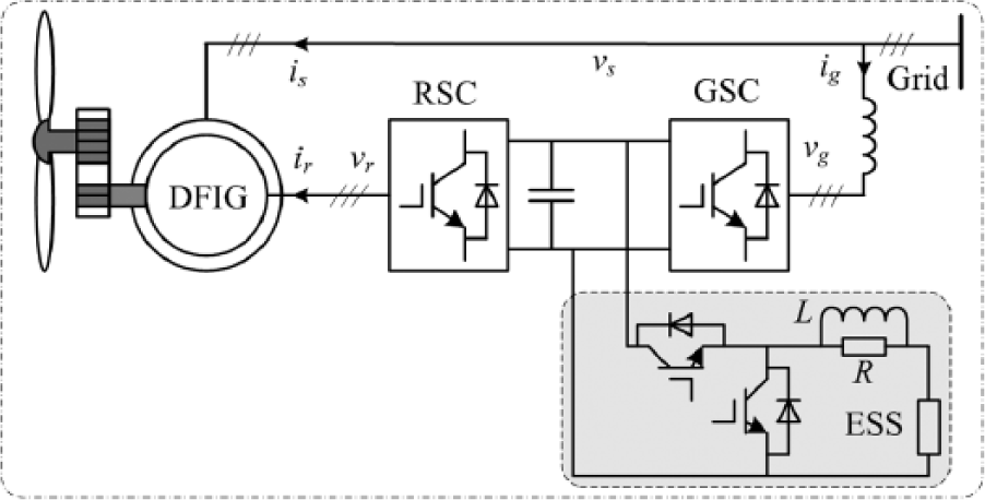
DFIG-based WT with energy storage system.
In addition, the FRT capability of DFIG-based WTs can also be improved by modifying pitch angle controller (Kamel, 2014; Ling et al., 2012a, 2013) or changing the WT gearbox ratio (Kamel, 2014).
Combined FRT schemes
At present, the combined FRT schemes are used widely and it is a promising FRT approach for WTs in the future due to their advantages. Typical combined FRT scheme for DFIG WTs is that of the CB plus DC chopper (Erlich et al., 2007b; Hu and Yuan, 2012). The advantage is there is no need to increase the size of the RSC. On this basis, an RS-CB is added to avoid frequent use of CB (Yang et al., 2008, 2010), while in Liang et al. (2010) an active FRT method for the RSC of DFIG is introduced for the same purpose without a new additional hardware circuit. It is well known that the hardware protection circuits itself is a disturbance for the DFIG system. Based on the CB protection, a STATCOM, acted as by GSC through reconfiguring the GSC, can be introduced to compensate reactive power, thus supporting the recovery of fault voltage (Meegahapola et al., 2010); flux damping strategy is proposed to mitigate oscillation in the stator flux during grid fault (Rodriguez et al., 2005) and an ESS is added to absorb the excess energy stored in the DC bus capacitor, thus attenuating the DC voltage ripple (Li and Zhang, 2010).
In addition, the use of the CB can be avoided in other combined FRT schemes (Esandi et al., 2009; Okedu et al., 2011; Rahimi and Parniani, 2010a). In Okedu et al. (2011), a new method using a DC chopper and an S-CB is proposed, while in Esandi et al. (2009), a combination of demagnetizing current and S-CB is adopted. The latter solution requires fewer hardware circuits and is further developed in Rahimi and Parniani (2010a) by injecting a nonlinear control, which can effectively stabilise DC bus voltage fluctuation during the grid fault for GSC.
The different FRT algorithms can also be combined to realize different control objectives of FRT for DFIG WTs based on their own advantages (Hu and He, 2011; Nian et al., 2011; Rathi and Mohan, 2005), such as a combination of the DPC approach with the sliding mode control (Rathi and Mohan, 2005) or with the PI-R controller (Nian et al., 2011) and an application of PI-R in VC method.
Case study
To increase the credibility of the analysis above, a case study has been carried out in the dedicated power system analysis tool PSCAD/EMTDC. In the case study, a combined FRT scheme has been proposed to show the performance of different schemes. The combined FRT approach includes, (1) an improved VC algorithm for RSC, (2) a CB circuit, and (3) a DC chopper circuit. The detailed DFIG WT simulation system can be seen in Figure 16, in which Figure 16(a) is the CB circuit and Figure 16(b) is the DC chopper circuit. The relevant parameters of the system in the simulation study are presented in Appendix 1.
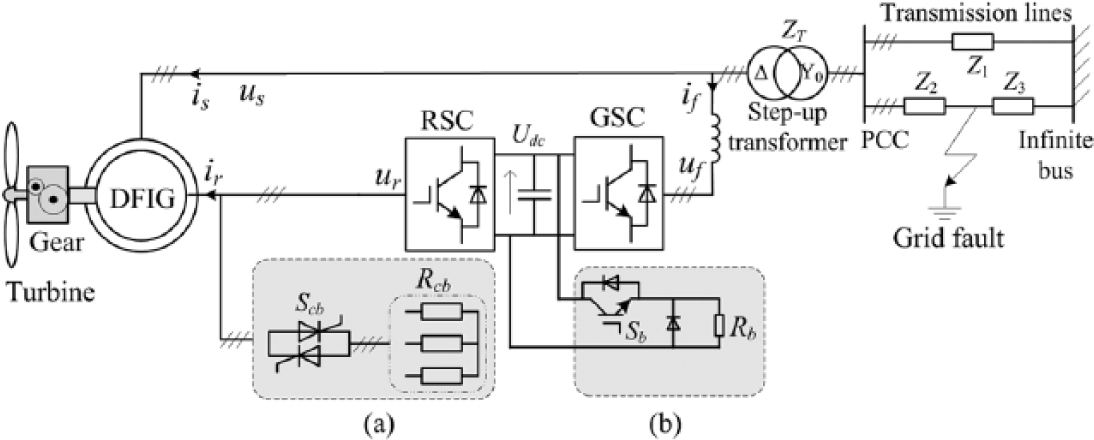
The detailed DFIG wind turbine simulation system: (a) CB circuit, and (b) DC chopper.
Figure 17(a) is a switch logic control system used for the CB circuit. When the rotor current Ir exceeds the rotor current limit Ir,lim, the switch signal Fcb changes from 0 to 1. This causes the switch Scb in Figure 16 to close, inserting the bypass resistors Rcb. This means that the current Ir begins to fall. When it falls to below the current Ir,lim, the signal Fcb returns to 0 and the switch Scb is opened again, removing the resistors Rcb. The signal control system used for the DC chopper circuit can be seen in Figure 17(b). The switch signal Fb can be generated by tuning a hysteresis controller with the input of the error between the DC-link voltage Udc and the DC-link voltage limit Udc,lim. When the error exceeds the voltage Udc,w, the signal Fb changes from 0 to 1. This makes the switch Sb in Figure 16 close, the unloading resistor Rb is inserted, and the error begins to fall. When the error falls below the voltage −Udc,w, the signal Fb returns to 0 and the switch Sb is opened again, removing the resistor Rb.
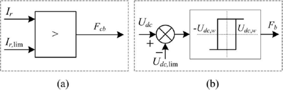
Logic control strategies for additional hardware circuits: (a) CB control signal, and (b) DC chopper control signal.
Figure 18 shows the conventional VC scheme for RSC, where the DFIG is controlled in a synchronously rotating dq-axis reference frame with the d-axis being aligned to the stator flux vector position. In Figure 18, θ1 is the supply angular position and θr is the rotor angular position. As shown in Figure 18, the reference current iqr,ref is derived from the error between the stator active power command and its measured value by tuning a PI controller, and the reference current idr,ref is attained from the error between the reactive power command and the actual reactive power, where the reactive power reference can be set at any value for considering power factor. The d- and q-axis rotor reference voltages, udr,ref and uqr,ref, can be derived from the sum of the error between the rotor current reference, idr,ref and iqr,ref, and the rotor actual current, idr and iqr, by tuning a PI controller and the rotor voltage feed-forward compensation terms, Δudr and Δuqr, respectively. Δudr and Δuqr are

where s is the slip, ω2 is the slip angular frequency, uqs is the q-axis stator voltage, Lls and Llr are the stator and rotor leakage inductances, respectively, Lm is the magnetizing inductance, and Ls = Lls + Lm, Lr = Llr + Lm; σ is

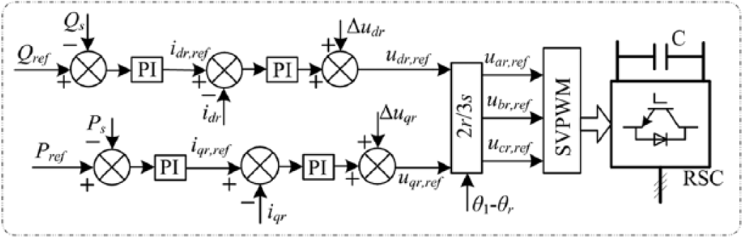
Improved vector control scheme for rotor side converter.
In the improved VC scheme for RSC, compared with the conventional VC, the main difference is that the stator dynamic terms are real-time introduced to the feed-forward voltage compensation terms. The rotor voltage feed-forward compensation terms, Δudr and Δuqr, become

where uds is the q-axis stator voltage, p is the differential operator, and ω1 is the supply angular frequency.
In the following simulation, at the moment of voltage dip, the rotor speed is 1.15 pu, and the generator power is close to 0.9 pu. Only three cases, voltage dips for 30%, 60%, and 80%, are investigated to evaluate the FRT capability of different FRT schemes. The voltage dips are applied at the DFIG stator terminals at 8 s and last for 625 ms. The rotor current limit Ir,lim = 2 pu. The DC-link voltage limit is 1.2 times its nominal value, that is, Udc,lim = 1.4 kV and the hysteresis band is 2Udc,w, that is 0.2 kV.
Figure 19 shows the responses of the DFIG WT to different grid voltage dips. As shown in Figure 19(a), when the DFIG is subjected to a voltage dip of 30%, both the rotor current and the DC-link voltage are far below their own limit values. So we can know that two additional hardware circuits are not activated. This result can also be obtained by their control signals shown in Figures 20(a) and 21(a), respectively. During this time, the signals Fcb and Fb do not change. That is to say, only with the improved control algorithm, the DFIG can ride through the lower voltage sag fault. With the increase in voltage sag, such as a voltage drop in 60% applied at the DFIG stator terminals, as shown in Figure 19(b), the rotor current will increase but still below its limit. According to the switch signal Fcb shown in Figure 20(b), the CB circuit is still not activated. However, the DC-link voltage fluctuates within its given range. The main reason is, according to Figure 21(b), the switch signal Fb changes from 0 to 1 or from 1 to 0 and the DC chopper circuit works well. That is to say, only with the improved control algorithm, the DFIG cannot ride through the moderate voltage sag fault. To limit the DC-link voltage within the limit, the DC chopper circuit needs to be activated. When the degree of voltage drop is increased to 80%, according to Figure 19(c), the rotor current will continue to increase but still remain within its limit. In fact, the main reason is that the CB circuit works well and plays a key role. This result can be concluded from its control signal Fcb, which changes (see Figure 20(c)). At the same time, according to Figure 21(c), the switch signal Fb changes from 0 to 1 or from 1 to 0, the DC chopper circuit is activated, and it limits the DC bus voltage within its given range. That is to say, all FRT methods are required in order to help the DFIG ride through the severe voltage dips.
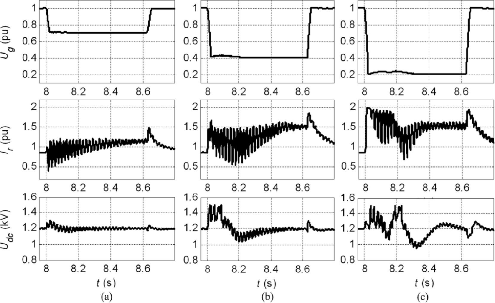
The responses of the DFIG wind turbine under different voltage dips with different FRT schemes: (a) with a voltage dip of 30%, (b) with a voltage dip of 60%, and (c) with a voltage dip of 80%.

Logic control signal of the CB circuit: (a) with a voltage dip of 30%, (b) with a voltage dip of 60%, and (c) with a voltage dip of 80%.
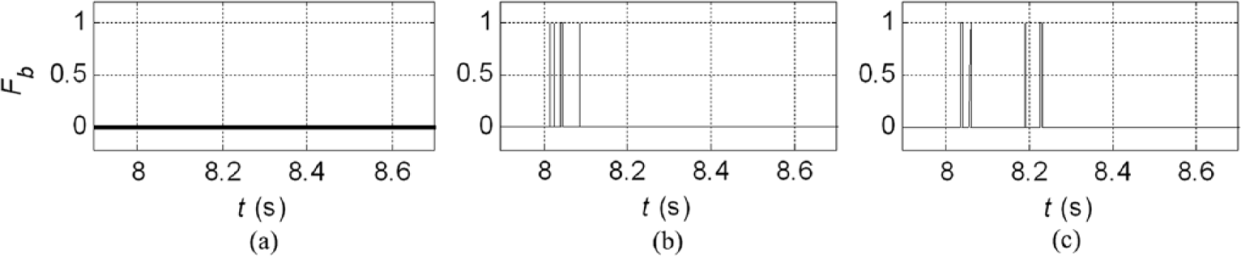
Logic control signal of the DC chopper circuit: (a) with a voltage dip of 30%, (b) with a voltage dip of 60%, and (c) with a voltage dip of 80%.
In short, according to the simulation results, the improved control algorithm for RSC only can help the DFIG successfully ride through the lower voltage sags. But the good control algorithm can minimize the occurrence of hardware circuits and reduce their effect on the DFIG WTs. With the increase in voltage sag, such as the moderate/severe voltage drop, in addition to the improved control algorithm, the relevant hardware circuit is also required to work together to help the DFIG successfully ride through the voltage faults. At the same time, it can also be seen that the combined FRT method is simple, easy to achieve, and is also effective.
Conclusion
In this article, a number of literatures on the different FRT solutions for DFIG WTs in recent years have been presented, and a comparison and analysis of these solutions are conducted on the basis of three broad categories. Their characteristics are substantially summarized as follows.
The FRT schemes based on additional hardware circuit enable the DFIG WTs to successfully ride through the grid voltage even zero voltage, but their usage means that the extra hardware needs to be installed in the system, and so this will result in an increase in cost and hinders their reliability. Moreover, these devices themselves are a disturbance for the DFIG-based WT system.
Regarding those drawbacks, the scheme-based control algorithms are needed. However, their FRT capability is limited by the limited capability of RSC.
As a result, the combined FRT scheme, especially a combination of simple hardware solutions and simple soft solutions, is becoming a popular and proposing scheme. An appropriate control algorithm can minimize the occurrence of hardware protections and reduce the effect on the DFIG WTs.
Finally, we should consider the actual situation as much as possible, and then determine the FRT scheme of DFIG WTs. For example, for the installed DFIG WTs that cannot provide sufficient FRT capability, a DVR is an appropriate FRT solution, despite the high cost of DVR.
Footnotes
Appendix 1
Rated power: Pn = 2 MW; rated stator voltage: Un = 690 V; rated frequency: f = 50 Hz; stator resistance: Rs = 0.00488 pu; stator leakage inductance: Lls = 0.1386 pu; rotor resistance: Rr = 0.00549 pu; rotor leakage inductance: Llr = 0.1493 pu; mutual inductance: Lm = 3.9527 pu; stator/rotor turns ratio: 0.45; inertial constant: H = 3.5 s.
ST = 2.5 MW, 20 kV/690 kV, ZT = 0.0098 + j0.09241 pu, Z1 = Z2 + Z3 = 0.01 + j0.1 pu.
CB circuit: Rcb = 0.5 pu; DC chopper circuit: Rb = 0.01 Ω.
Proportional gain of power control: kp = 0.05; integral time constant of power control: t = 0.2; proportional gain of current control: kp = 0.3; integral time constant of current control: t = 0.12.
Base capacity: Sb = 2.2 M VA; base frequency: fb = 50 Hz; base stator voltage (phase, peak value): Usb = 563 V.
Declaration of conflicting interests
The author(s) declared no potential conflicts of interest with respect to the research, authorship, and/or publication of this article.
Funding
The author(s) disclosed receipt of the following financial support for the research, authorship, and/or publication of this article: This work was supported by the Natural Science Foundation of Shanxi Province (2015011065), the Datong Basic Research Project (2015112) and the PhD Research Start-up Funds of Shanxi Datong University.