



Abstract
In this article, the supervisory controller is proposed to manage a hybrid wind turbine generator and a grid supplying a village load. The main problem is the compatibility of coupling of different sources. To avoid this problem, the grid supplies a motor to supplement the torque of the wind turbine when the wind speed is low, and the village demand is higher than the wind turbine generator power. On the other hand, the excess power from the wind turbine generator can be absorbed by a dynamic power load that is connected to the grid. The fuzzy proportional–integral/proportional–integral–derivative supervisory controller objectives are to stabilize the frequency and voltage of the system and satisfy the village power demand. This is achieved by balancing the active and reactive powers of the wind turbine generator and village load through a grid contribution. The whole system has been simulated using SIMPOWER in MATLAB/SIMUILINK software. The efficiency of the proposed controller has been proved by the obtained results.
Keywords
Introduction
In the last few years, power generation by the renewable energy systems (RESs) are gradually more replacing the conventional energy, not just because they are free energy sources but also they have many environmental positive impacts (Arul et al., 2015; Guerin et al., 2012).
Although the RESs have the above-mentioned advantages, they also have serious disadvantages and the most important ones are as follows: unpredictable behaviors of nature like solar irradiation or wind speed variations with the fluctuations of power load demand can make negative effects on the power quality (Garcia et al., 2014). As well as, the power quality can be represented by voltage or frequency deviation; in addition, there is a relationship between active power and frequency and between reactive power and voltage. This phenomenon is called droop characteristic (Bevrani, 2009).
RESs such as wind turbine generator (WTG) connected with the grid can solve these problems by exchanging the electrical power between the grid and the WTG (Saqib and Saleem, 2015).
One of the major problems of hybrid energy system in DC or AC coupling is the compatibility of different sources, which required a lot of power electronics and complex control (Nehrir et al., 2011; Yasmeena and Tulasiram Das, 2015). Thus, the proposed grid can give more power to the village when the WTG cannot satisfy the village power demand by helping the generator of the wind turbine (WT) through a motor, so the motor is integrated in the WT and the grid can boost the power of the system by giving a mechanical power to the WTG which can reduce the hybrid energy coupling problems. On the other side, the proposed grid can be just absorbed the excess power from the WTG through a dynamic load.
The article is organized as follows: the system modeling is described in section “System modeling”; the supervisory controller based on fuzzy-proportional–integral–derivative (PID)-proportional–integral (PI) controllers is proposed and discussed in section “PI and PID controllers.” Section “Results” gives the simulation results using SIMPOWER in MATLAB/SIMULINK. Section “Conclusion” concludes the article.
System modeling
In Figure 1, the proposed system consists of asynchronous generator connected to a WT. The grid supplied motor provides a torque for the asynchronous generator in case of low wind speeds. This hybrid system supplies loads that are modeled as a dynamic load and the village loads.
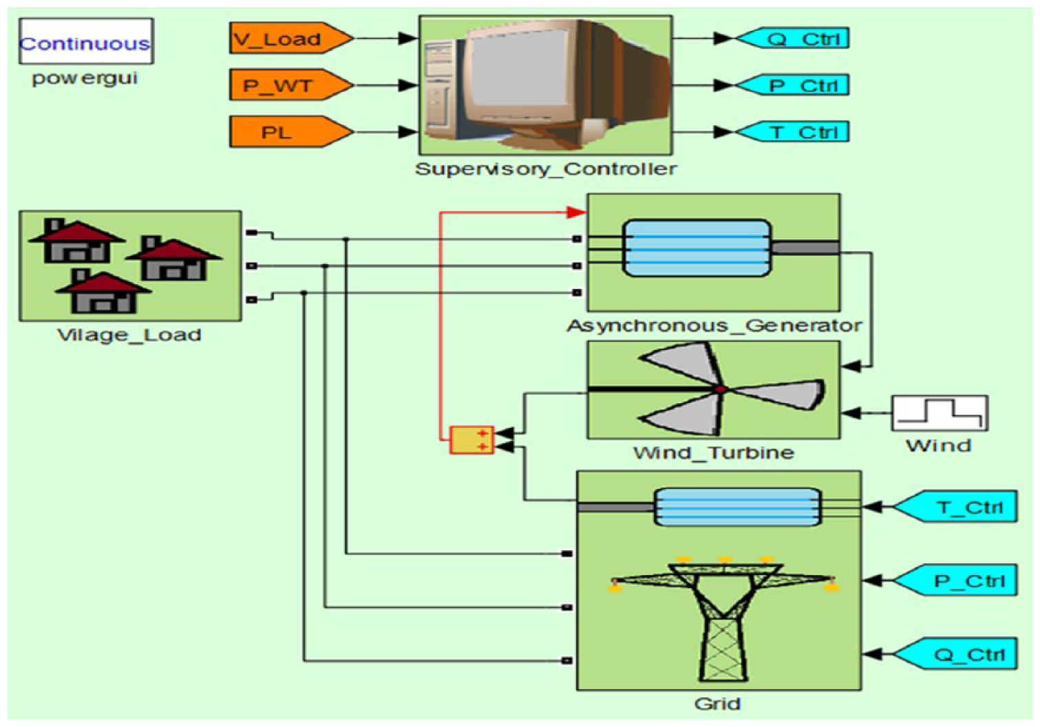
Hybrid energy system.
Wind turbine
The WT can produce a mechanical power from the kinetic energy of the wind (Mukund, 1999). Thus, the torque of WT can be represented by following equation (Qi et al., 2011)

where Cp is the power coefficient, ρ is the air density, A is the area of windswept, R is the turbine radius, and V1 is the wind velocity.
Motor
The role of the motor in this system is to help the WT to produce an effective torque for the generator to stabilize the frequency and to satisfy the village power demand when the active power consumption is higher than the active power delivered from the WTG. The torque of this supplemented motor is proposed as first-order equation

where TM_ ctrl is the torque reference and τM is the time constant.
Asynchronous generator
In this work, the squirrel-cage asynchronous machine model from SIMULINK library is used. This machine consumes reactive power and therefore power factor correction capacitors are inserted as shown in Figure 2 (Anaya-Lara et al., 2011).

Schematic diagram of a fixed-speed wind turbine.
The mechanical power of the squirrel-cage induction machine is given from the WT and the supplement motor. The equation of mechanical power is given by (Lin et al., 2015)

where Tem is the electromagnetic torque, ωr is the angular speed of the rotor, J is the inertia, and B is the damping coefficient. The parameters of the asynchronous generator are presented in Table 1 (Gagnon et al., 2002).
The parameters of the asynchronous generator.

Loads
There are two kinds of loads in this project: the village load and the grid load. The objective of the WTG is to assure the electricity to the first load. On the other side, the second type of load has to absorb the excess power from the WTG. Those loads are modeled as dynamic loads from the SIMULINK library as shown Figure 3.

Three-phase dynamic load.
Supervisory controller
The aims of supervisory controller are as follows: to solve the droop characteristic problem and to assure the permanent electrical power supply to the village. Droop characteristic is the phenomenon engendered by the existing relationship between the active power and the frequency, and between the reactive power and the voltage.
If the production of active power is higher than the consumption, then the network frequency decreases and vice versa. The same relationship exists also between the voltage and the reactive power. The general expression of the droop characteristic phenomenon is as follows (Bevrani, 2009)


where f and f0 are the actual and reference frequencies, respectively; PL is the active power of the load; PG is the generated active power from hybrid system; and D1 is the droop coefficient.
V and V0 are the actual and reference voltages, respectively; QL is the reactive power of the load, QG is the generated reactive power from hybrid system; and D2 is the droop coefficient.
From the above problems, it is clear that the idea of the supervisory controller is to regulate the frequency and voltage by controlling the active and reactive powers. In addition, the active power PI controller allows the absorption of the WTG excess power. When the load (PL) and generated (PG) powers are equal, the frequency will be stable at 50 Hz. In case that the wind speed is low, the WT cannot produce enough mechanical power to the generator. PL is then higher than PG. The torque PID controller orders the supplement motor to provide an additional torque to the WT until PG reaches PL. Consequently, the frequency becomes stabilized.
The role of fuzzy logic controller (FLC) is to make a decision on which controller would be activated.
The PI controller of the reactive power is always activated to compensate the reactive power of WTG and village loads. This controller regulates the reactive power in order to get always a voltage of 480 V (Figure 4).

Supervisory controller block diagram.
PI and PID controllers
As mentioned before, the supervisory controller uses two PI controllers for the active and reactive powers, a PID controller for the supplement motor torque.
The PI active power controller regulates the network frequency by giving the excess power to the grid loads. The following equation represents the PI controller with its parameters

where UA is the active power control variable. Kap = 13 × 104 is the proportional gain, Kai = 106 is the integral gain, and ef is the frequency error. The PID motor torque controller regulates the frequency of the network by giving a more torque to the WTG asynchronous generator. It is given by the following equation

where UT is the active power control variable. Ktp = 3.5, Kti = 4, and Ktd = 1 are the proportional, integral, and derivative gains, respectively. The PI reactive power controller regulates the network voltage by compensating the reactive power of the grid loads. It is given by the following equation

where UR is the active power control variable. Krp = 5 × 10⁵ and Kri = 105 are the proportional and integral gains, respectively. ev is the voltage error.
Fuzzy logic controller
The proposed FLC consists of an input and an output. The input is the error power between the WTG and the load powers. The output is the switch control variable. The FLC is generally achieved through three steps: fuzzification, rule base and inference, and difuzzification.
Fuzzification
There are three linguistic variables for the input: negative, good, and positive as shown in Figure 5 and also there are three linguistic variables for the output: OnCtrl1, OffCtrl12, and OnCtrl2 as illustrated in Figure 6.
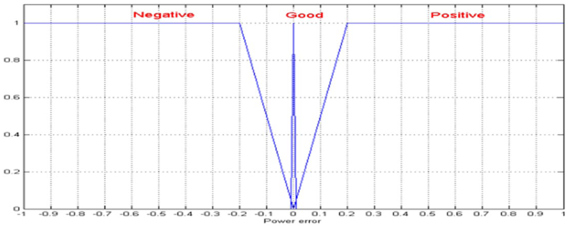
Error input.
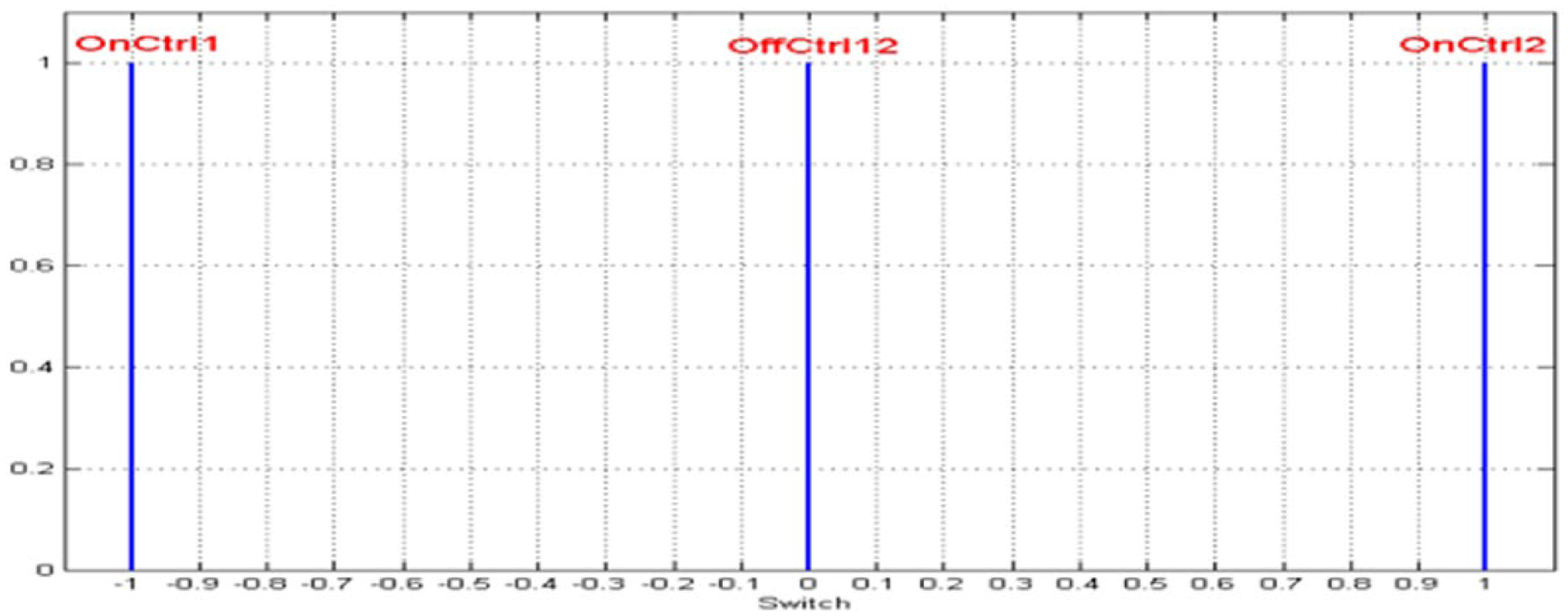
Switch control output.
Rule base and inference engine
The fuzzy rule algorithm includes three fuzzy control rules listed in Table 2. Fuzzy rule setting transforms the fuzzy rule base into fuzzy linguistic output. In this article, Mamdani’s fuzzy inference method with max–min operation fuzzy combination has been used.
Rule base.

Defuzzification
This operation converts the inferred fuzzy control action into a numerical value at the output by forming the union of the outputs resulting from each rule.
Results
Two wind profiles have been simulated. The first one studies the system when the wind speed varies for each 20 s as illustrated in Figure 7. The torque, active, and reactive powers of the village load, WTG, and grid are shown in Figures 8 to 10, respectively. The results in Figure 8 show that the PID torque controller had fast effect on the motor torque, when the WT torque cannot give enough torque. Also the total torque that enters to the generator is shown in this figure. For example, between 20 and 40 s, the produced torque from the WT is approximately −0.18 pu but it is not enough for the generator so the motor torque gives about −0.22 pu of torque value. Between 40 and 60 s, the WT torque is about −0.98 pu and equal the total torque. In fact, it satisfied the generator’s needs. In Figure 9, the excess active power from the WTG that is absorbed from the grid loads proves that the PI active controller do its task with high performance. In addition, the load active power is 110 kW all the time and between 0 and 20 s the WTG active power is −143.4 kW.
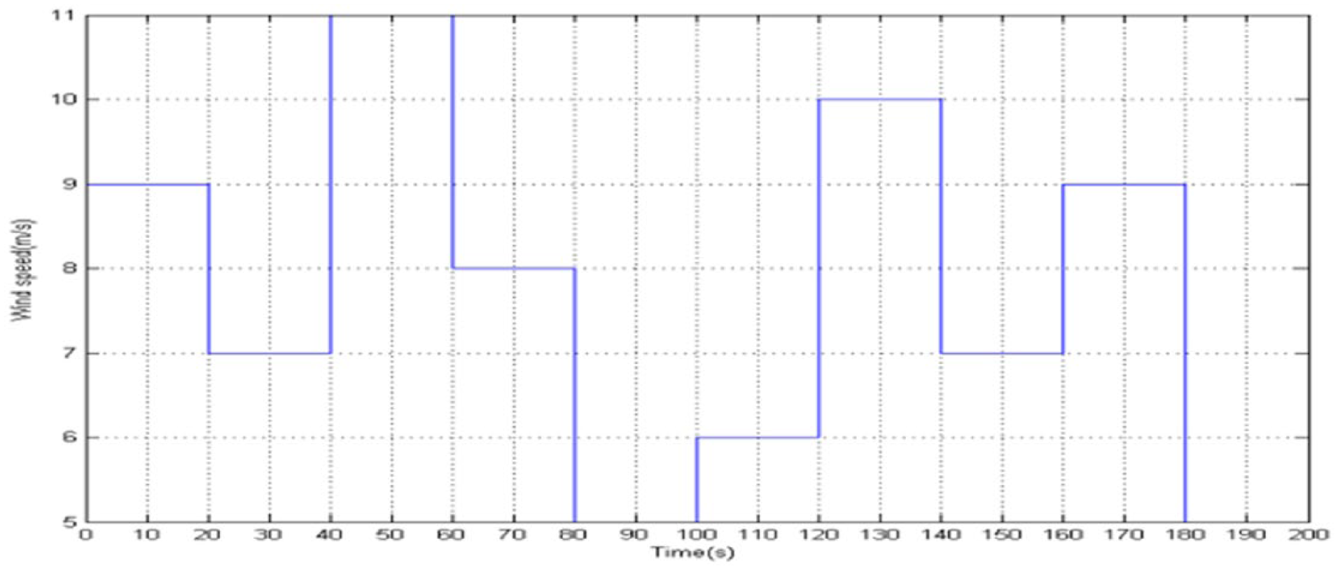
Wind speed profiles in case 1.
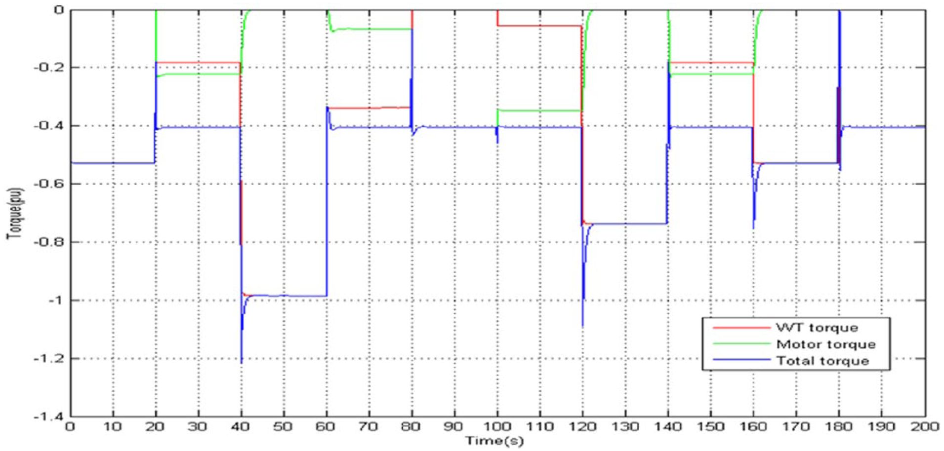
Torque of motor and WT in case 1.
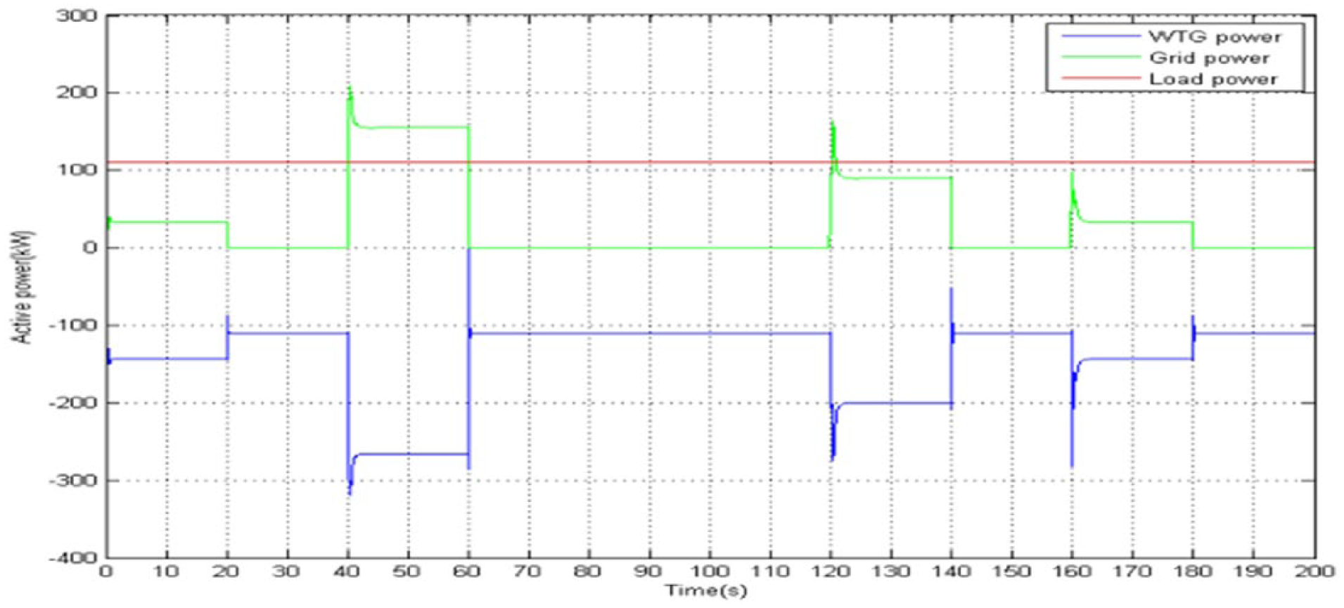
Active power of the WTG, the grid, and the load in case 1.

Reactive power of the WTG, the grid, and the load in case 1.
The absorbed power from the grid (which is modeled as active load) is approximately 33.42 kW. Between 40 and 60 s, the WTG and the grid active power are about −265.8 and 155.4 kW, respectively. Between 120 and 140 s, they are −199.8 and 89.68 kW, respectively.
And finally between 160 and 180 s, these powers are −143.5 and 33.54 kW, respectively. For times between 20 and 40 s, 60 and 120 s, 140 and 160 s, and 180 and 200 s, the absolute active power of the WTG was equal to the village load active power.
The fuzzy logic contribution can be observed in Figures 8 and 9 because when the grid absorbs the active power, the motor torque is equal to zero and vice versa. Also the switching between the two controllers was very smooth. The reactive power PI controller balances the reactive powers of the WTG and the village load by the grid load reactive power as shown in Figure 10. Furthermore when the time, for example, is between 80 and 100 s, the compensation capacitors always have −75 kvar where the village load and the WTG are 83.8 and 16.5 kvar, respectively. To compensate the reactive power of WTG, the grid (modeled as capacitive load) is activated to −24.56 kvar.
Figures 11 and 12 represent the electromagnetic torque and rotor speed of asynchronous generator, respectively, in the first case. Between 20 and 40 s, 60 and 120 s, 140 and 160 s, and 180 and 200 s, the electromagnetic torque and the rotor speed are approximately fixed to −0.4 and 1.0062 pu, respectively. The absolute active powers of the WTG and the village load were the same with the support of the motor torque. On the other side, the electromagnetic torque and the rotor speed vary because the WTG was produced further power than the village needs.

Electromagnetic torque of the asynchronous generator in case 1.

Rotor speed of the asynchronous generator in case 1.
The first objective of this work is to stabilize the frequency and voltage of the village load. Figure 13 illustrates the three-phase voltage of the network where the maximum value was proportionally steady with the acceptable noises. On the other side, the frequency of this voltage is illustrated in Figure 14, where we notice tolerable perturbations.

Three-phase voltage of the load in case 1.

Frequency of the load in case 1.
To verify that the supervisory controller can work and give good results with real and complicated scenario, a second test is performed. In the second case, the wind profile is more complicated than the first case, that is because the wind speed varies for each 50 s as shown in Figure 15. The results are presented in Figures 16 to 18 for the torque, active, and reactive powers, respectively. The results have the same performance as the first case. For example, between 0 to 20 s, the WT and the motor torque are approximately −0.18 and −0.32 pu where the total torque is −0.5 pu. On the other hand, between 60 and 80 s, the active powers of the WTG, the load, and the grid are −266.3, 192.5, and 74 kW, respectively. In this period, the reactive powers of the WTG, the load, and the grid were approximately 112.3, 10.2, and −47.83 kvar, respectively.

Wind speed profiles in case 2.

Torque of motor and WT in case 2.

Active power of the WTG, the grid, and the load in case 2.

Reactive power of the WTG, the grid, and the load in case 2.
Figures 19 and 20 represent the electromagnetic torque and rotor speed of asynchronous generator, respectively. In the second case, they always vary because the WTG and village active power were not fixed all the time.

Electromagnetic torque of the asynchronous generator in case 2.
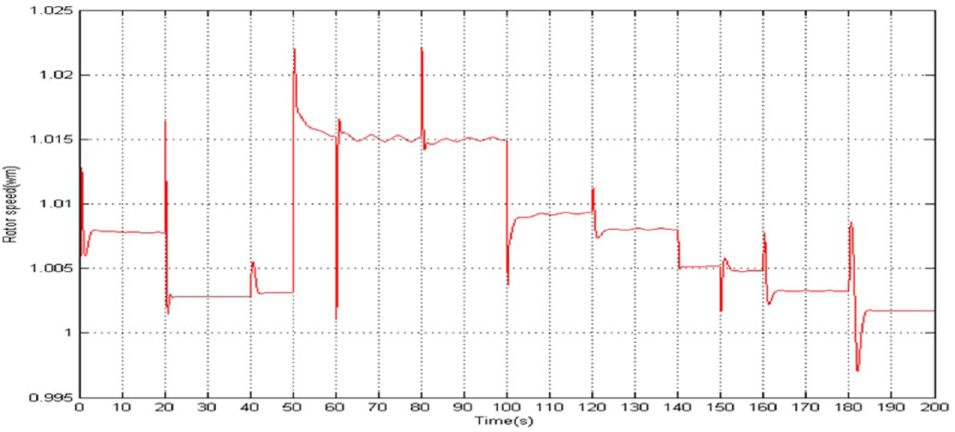
Rotor speed of the asynchronous generator in case 2.
So the village load power demand is satisfied. As shown in Figures 21 and 22, the voltage and frequency, respectively, are at acceptable standard values.
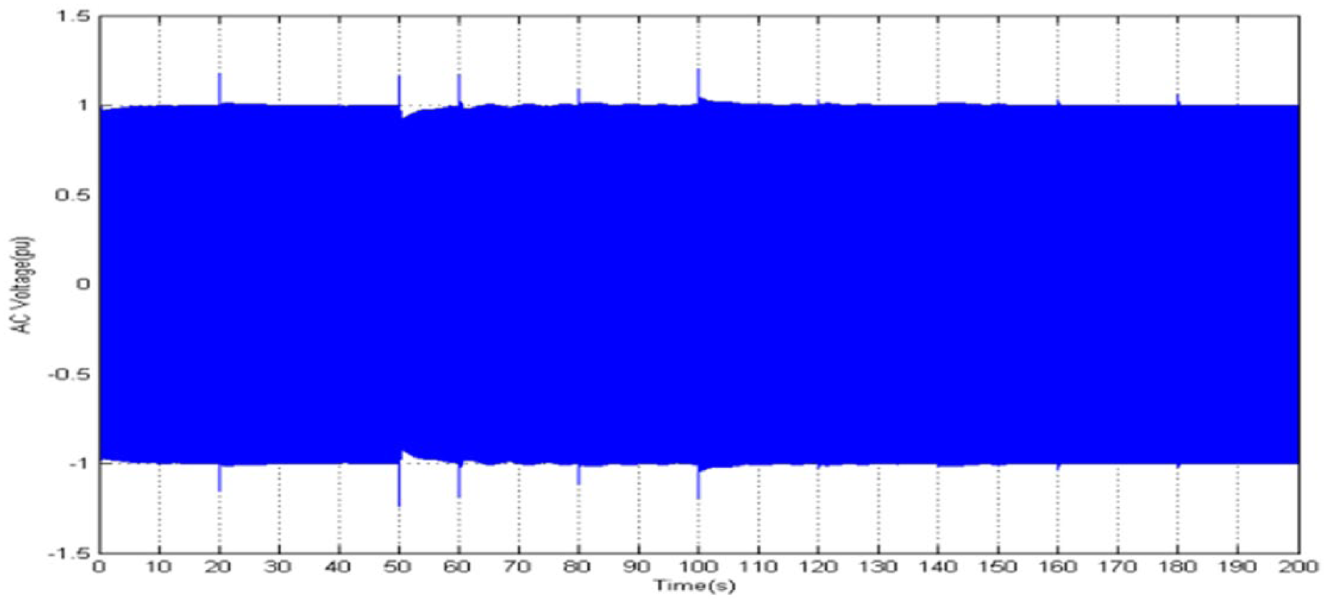
Three-phase voltage of the load in case 2.

Frequency of the load in case 2.
Conclusion
In this article, a fuzzy-PID-PI supervisory controller is proposed to solve the droop characteristic problem and to satisfy the village load power demand. The village needs were supplied from a hybrid energy system.
The RES that consists of the WTG, the asynchronous motor, and the gird has been modeled by SIMPOWER in MATLAB/SIMULINK. The grid was connected to a motor in order to support the WT to produce further mechanical power when the wind speed is low or the village demand needs more electrical power. But if the WTG produces more electrical power than the village needs, the grid absorbs the excess power that is not consumed by the dynamic load. Satisfying results of the supervisory controller have been obtained. The objectives in terms of grid voltage stability and frequency regulation have also been reached. The grid three-phase voltage magnitude and frequency were maintained within the standard acceptable values.
Footnotes
Declaration of conflicting interests
The author(s) declared no potential conflicts of interest with respect to the research, authorship, and/or publication of this article.
Funding
The author(s) received no financial support for the research, authorship, and/or publication of this article.