



Abstract
Although integration of wind distributed generation directly into the distribution level has considerable advantages, increased penetration of wind distributed generation (renewable distributed generation) alters the network configuration and jeopardizes the protection system operation and system stability; for this reason, necessary changes in power system protection philosophy must be achieved. Modern numerical relays offer extraordinary features and fast and accurate methods for spotting and detecting different unbalanced operating conditions and can be used to mitigate the influence of integrating wind distributed generation into distribution network. In this study, an adaptive directional negative protective scheme was implemented in the medium-level distribution network to investigate and evaluate the performance of protection system and introduce new adaptive protective scheme based on negative overcurrent protection to increase the selectivity and sensitivity of the protection system in case of unbalanced faulty conditions. The medium-level distribution network of Libya Eastern electric network had been implemented in ETAP software to address and evaluate the efficiency of the proposed approach.
Introduction
Libya is one of the largest oil-producing countries located in the central part of North Africa with 1,750,000 km2 total land area. It is gifted with 1900 km coastline along the Mediterranean, resulting in a very high potential for solar and wind energies. The majority of the country’s people live in the coastline area. The current population of Libya is approximately 6,273,000 (Asheibi et al., 2015). With the best location and the abundance of the solar energy and wind energy supplies, Libya’s contribution is still negligible. Electrical energy generation in Libya is mainly dependent on fossil fuel, oil, and gas. After the destruction that happened in the country’s infrastructure during 2011, it reduced oil and gas production, which are the main source of income for the country. This, in turn, resulted in drastic reduction in the country’s revenue as well as electricity shortage.
Moreover, in the near future, the energy demand will significantly increase as a result of the economic development and rebuilding a new infrastructure (Khalil et al., 2016a; Libya Infrastructure Report, 2012). The status of electricity generation in the country should be taken into consideration in terms of energy shortage, its complete reliance on fossil fuels, and its harmful emissions. This triggers the alarm for the country to make an urgent plan to utilize renewable energy source.
However, the renewable energy has been in use in Libya since 1970s; the main applications were for powering small remote loads. Since 1976 the use of photovoltaic (PV) systems has started to supply electricity for a cathodic protection station for the oil pipeline connecting Dahra oil field with Sedra Port. Moreover, in 1979 four experimental stations in communication field were installed. In 1983, solar water pumping project was started, where water was pumped for irrigation in the El-Agailat city. On the other hand, wind energy is considered a new technology in Libya. In 2010, project on the scale of 60 MW wind farm was installed in Al-Fattaih, in the city of Dernah, eastern Libya. Dernah has a high potential of wind and solar energy.The average wind speed is roughly between 6 and 7.5 m/s at 40 m height (Asheibi et al., 2016; Asheibi and Khalil, 2013; Khalil et al., 2016a; Libya Infrastructure Report, 2012; Rajab et al., 2017).
Wind turbines, which produce electricity from wind, are set to become an important source of renewable energy in Libya. It is time to predict the extent of the impact they may have, but all the signs are that they will play a significant role in the future. Wind energy has gathered a lot of attention in the past few years. According to Asheibi and Khalil (2013), 10% of the energy required by the globe could possibly be supplied by the wind in the next decade. The dynamic response of squirrel cage induction generator (SCIG) with direct grid connection is carried out. Inrush current developed by the machine when coupled directly to the grid, the couple presented a fluctuation and harmonic (Mehimmedtsi and Rachid, 2013). 36 MW fix speed wind farm is proposed to grid connected in Fawzi and Ghosh (2012). It is found that the study was done through calculating its power curve and investigating the effects of wind speed at the beginning.
In this article, a simulation for 30-kV Libya Eastern Electric Network had been carried out, a comparison of phase overcurrent protection with directional negative sequence overcurrent protection for different fault types and location had been done, and investigation for the impact of transformer configuration on unbalanced fault currents had been done. An adaptive protection scheme had been introduced to mitigate the protection issues arising from integration wind energy sources in the electric grid.
Wind energy potential in Libya
Libya is blessed with perfect condition for renewable energy sources, mainly solar energy and wind energy. Wind energy was utilized for water pumping since 1940, the use of wind systems has developed as the wind-mills which require some maintenance from time to time. In 2004, measurement of the wind speed for wind potential was conducted. The measurements showed that there is a high potential for wind energy in Libya, and the average wind speed at a height of 40 m is between 6 and 7.5 m/s (Asheibi et al., 2016; Asheibi and Khalil, 2013; El Naily et al., 2017; Khalil et al., 2016b; Libya Infrastructure Report, 2012; Rajab et al., 2017). Figure 1 shows the average wind speed for different cities in Libya. Previous research (Mohamed MAA et al., 2013) reported that the possibility of utilizing wind energy in electricity generation in some locations and connecting it with the nation grid is high as in case of Benina, Sirt, Dernah, Sebha, and Tolmetha, whereas in other areas such as Ejdabia and Sorman it is more favorable to use wind energy for water pumping and other applications. Wind energy potential for electricity production has not started yet. On research aspect, a potential of 1.65-MW wind power generation system in Derna Libya was evaluated (El Naily et al., 2017).
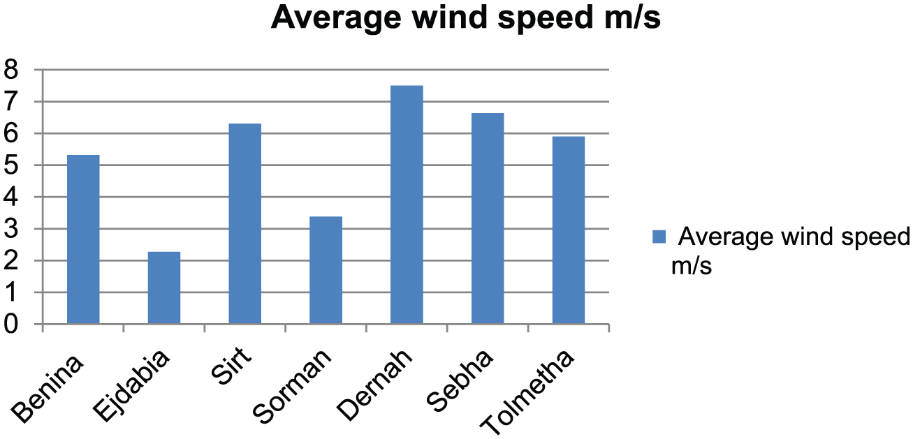
Average wind speed for different cities in Libya.
The wind farm turbines in Dernah, Libya
Dernah wind farm turbines are located in Dernah city, which is located on the coastline of Mediterranean around (320 29′ 16.728″N latitude, 200 49′ 54.264″ longitude), in the eastern part of Libya as shown in Figure 2.

The geographic situation of Dernah, Libya.
The wind farm is connected to the grid through step-up transformer to the 30-kV busbar. The wind turbines harvest the kinetic energy from wind and convert it into a usable form of energy. The kinetic energy from wind rotates the blades of the wind turbine. The blades are connected to a shaft. The shaft is coupled to an electric generator. The generator converts the mechanical power into electrical power (Mohamed et al., 2013)

where ρ is the air density (kg/m3), Pm the mechanical power (W), Cp the power coefficient of the turbine, A the swept area (m2), and vw the wind speed (m/s). The power coefficient Cp represents the conversion efficiency of the turbine. If the pitch angle β = 0, Cp is a function of the tip speed, λ, of the turbine and is given by Mehimmedtsi and Rachid (2013)

where λ = ωR/vw, ω is the rotational speed (rad/s), and R is the radius of the blades. The maximum power can be extracted from the turbine and can be achieved when Cp = 0.42 and λ = 6.5. The coefficients c1–c6 are as follows: c1 = 0.5176, c2 = 116, c3 = 0.4, c4 = 5, c5 = 21, and c6 = 0.0068. The wind turbines used in the simulation have the following specification: power rating of 3 × 1.65 MW, rated wind speed of 12 m/s, cut-in and cut-out speeds are 3 and 25 m/s, respectively, and blade diameter is 40 m. The power of the wind turbine versus wind speed and aerodynamic coefficients are shown in Figure 3.
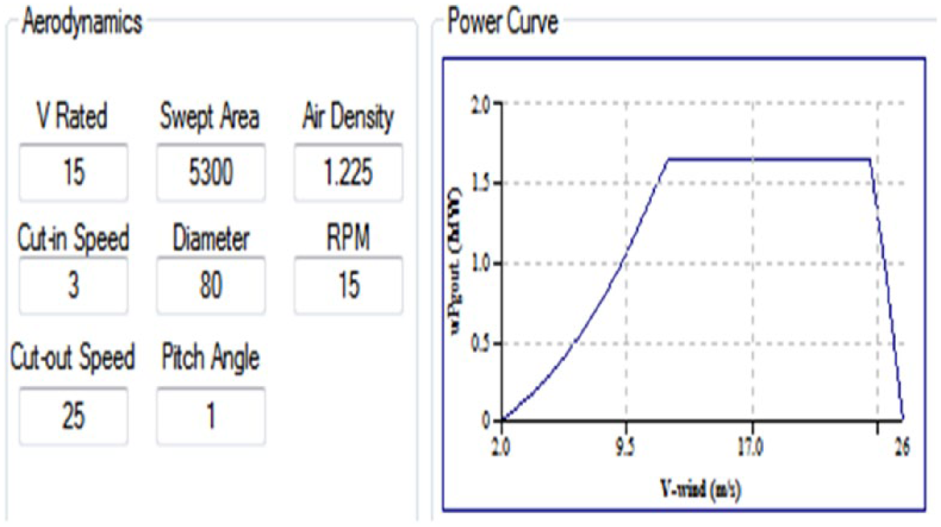
Power versus the turbine speed.
Squirrel cage wind turbine system
The wind turbine is composed of a turbine which converts wind energy into rotational mechanical energy and a generator which converts the mechanical energy to electrical energy. The electrical energy output of the generator is connected to a grid or load. There are numerous types of electrical generators, a direct current (DC) machine, a synchronous machine, or an induction machine (El Naily et al., 2017). Due to the presence of brushes and commutator segments, DC generators have low reliability and require very frequent maintenance. Due to their high efficiency, synchronous generators may seem like a good choice. But for the field winding a DC supply is required which adds to their cost. On the other hand, permanent magnets can replace the DC supply but magnets are subject to partially or fully losing their magnetism which reduces the reliability and the robustness of the synchronous generator. Synchronous generators operate in fixed speed which precludes the maximum power tracking. In the work conducted herein, induction generator is used because it is relatively cheap, easy to construct, robust, and almost maintenance free. In addition, they can operate at variable speed and thus they can be utilized for maximum power tracking (El Naily et al., 2017; Tahir et al., 2017). The specifications of the SCIG used in this study are shown in Table 1.
SCIG parameters.

Disturbance of protection during faults
The function of protection system in the distribution network (DN) is to protect the network against external as well as internal faults. The role of protection coordination in DN in the presence of wind distributed generation (DG) is to acquire a proper coordination based on the pre-fault load current and the power system impedance and the capacity of wind DG located in the DN. In the presence of wind DG, new configuration between the protective relays should be deduced (El Naily et al., 2017; Robitaille et al., 2012; Saad et al., 2017). The philosophy of protection coordination in traditional distributed network is simple in nature, which relies on the concept of single-fed source where the power flows in one direction (Grond et al., 2013; Poudineh and Jamasb, 2014; Yadav and Srivastava, 2014). However, integration of wind DG into the DN changes the topology of the DN from being radial to becoming looped topology and requires modification of all protective relay settings and characteristics (Liu et al., 2016; Samper and Vargas, 2013a, 2013b). Loss of coordination of protective relays in DN with renewable distributed generation (RDG) is quite possible if optimum coordination is not achieved. Blinding of protection is one of the common problems with RDG insertion. Figure 4 shows a blinding of protective relays when a fault strikes on feeders near RDG. The contributed current from RDG decreases the fault current from the main feeder and delays the operation of the main protective relay, which results in maintaining the fault for a longer time than expected and even could prevent the protective relays from picking up. Selectivity and dependability of the protection system in those scenarios could be tolerance as a consequence of poorly coordinated setting (Ahmadigorji and Amjady, 2014; Arriaga et al., 2016).

False tripping due to fault in another feeder.
Another protection issue is when RDG connected to the same busbar experiences a fault, a nuisance trip in the operation of the protective relay on the feeder containing renewable energy source (RES) could happen. The probability of protective relay false tripping depends on the capacity of RES and its location on the feeder (Alvarez-Herault et al., 2015; Sadeghi and Kalantar, 2014). The operation of autorecloser in overhead transmission line could also be affected by the integration of RES in the network. The continuous contribution of RES in a case of fault disturbs the operation of autorecloser and prevents it from clearing fault properly causing failure in autorecloser mechanism. Islanding could also be an issue for protection and control of DN if proper coordination is not acquired when the main feeder is disconnected from the grid while RES still supplies loads; islanding scenarios could diminish the protection coordination as well as minimize the power quality of the power supply (Acosta et al., 2010; Hyun et al., 2011). Other protection problems caused by DG could impact the operation and performance of the protection system in the DN such as, neutral shifting, resonance, and fuse saving operation, which require further adjustments in the protection system topology and design (Fernandez et al., 2011).
Impact of wind DG on power quality
Voltage regulation may become a problem in the presence of RDG due to the irregular nature of the RDG technology, like in the case of wind turbine and PV cells (Ruwaili et al., 2013). Also, RDG technologies lack the ability to produce reactive power and compensate for the voltage reduction on loaded busbars. Furthermore, interruption of large RDG units could influence the reliability and stability of the entire network. Voltage fluctuation is another power quality problem that occurs due to the intermittent nature of RDG (Slootweg and Kling, 2003). Consumption of reactive power when starting induction generators could cause voltage dip in the busbars near RDG. Also, switching RDG away from the grid due to short-circuit conditions leads to a significant decrease in the voltage magnitude and jeopardizes the stability of the network (Khushalani et al., 2007).
Some DG technologies connected to the electric network through power electronic converters such as wind turbine work with double-fed induction machine and PV are sources of harmonics in the electric network. The capacitors used for induction generators are also a source of harmonics in case of resonances in the network (Persaud et al., 2016). The increase in integrating single-phase RDG into DN could influence the voltage profile and create an eminent unbalancing issue (Slootweg and Kling, 2016).
Proposed methodology
The advance in digital relays provides eminent solutions and methods to increase the sensitivity of protection relays for ground faults. Directional negative sequence overcurrent methods enhance the fast detection of single-line faults in the DN. Also, the advances in the communication schemes aid the protection system speed and dependability, and as a result the electric network stability. In this study, comparison of the negative sequence overcurrent protection with phase overcurrent relays (OCRs) with emphasize on the advantages of negative sequence OCR in case of unbalanced faults in the grid was done. Discussion of the problems in the area of unbalance conditions had been carried out, and recommendation and application consideration had been addressed for optimum and correct protection coordination (El haffar et al., 2015).
The proposed approach in this article suggests employing the adaptive group scheme, which is an online activity which automatically changes the protection setting from one group to another in numerical protective relays in case of any change in system topology by means of control action. The adaptive group scheme in numerical relays modifies the protective relay settings based on system configuration and penetration level of RES in the DN to maintain the time current characteristic (TCC) between OCRs and preserves the selectivity and sensitivity of the protection system (Chandran et al., 2014). The internal logic functions (called contiguous function chart (CFC)) in the numerical relay are designed to sense the events and send the signal through any available communication medium to the targeted relays. The protection settings are adapted to the changes in the network configuration using the communication media available. In this article, the wireless network (Elmadar), which has a very good coverage, has been adopted as the main link among the protection relays (Schaefer et al., 2010). The proposed methodology avails the advantage of communication technology and digital protective devices that exist nowadays to design an automatic protection coordination based on the network operator experience. It is already a well-known fact that the modern relays have the ability to switch between multiple groups of TCC curves based on the system operating conditions (Dang et al., 2011). The proposed algorithm defines multiple groups of current settings, based on the RDG capacity and the fault current contributed from the RDG. The study offers guidance for selecting and optimizing OCRs for ground faults on underground cables.
In this study, calculation had been performed for three-phase fault and unsymmetrical faults. The calculation started with three-phase faults, not for their severity or being the most common type, but for their simplicity (Laaksonen et al., 2012).
Representation of transformers in sequence networks
In short-circuit studies, the magnitude of fault current is most significant than phase shift introduced by a transformer, thus the transformer is usually represented by positive, negative, and zero sequence impedances. Figure 5 illustrates the shift occurring in a transformer connected in delta–wye grounded (Mohamed and Koivo, 2010).
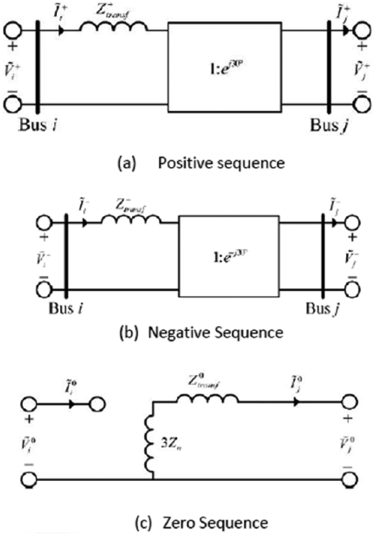
Equivalent sequence networks of a transformer connected in delta–wye grounded (Roberts et al., 1997).
Negative sequence overcurrent
Microprocessor protective relays facilitate applying negative sequence protection which enhances the selectivity of protection system to detect weak unbalanced faults and minimize the difficulty and complexity to implement negative sequence protection in electromechanical relays. Modern digital relays offer the feature of activating negative sequence element beside phase overcurrent element in the same protective relay, which improves the sensitivity and the economical aspect (Blackburn, 1998).
Negative sequence currents are present whenever unbalanced fault occurs in the network. It gives an advantage over zero sequence protection since transformer configuration could deduce the magnitude of zero sequence component in the fault current.
Negative sequence current is derived from the three-phase currents and is given by

where a = 1°∟120° and a2 = 1°∟240°.
The phase rotation in equation (3) is assumed to be positive ABC. Moreover, negative sequence relays are not affected by mutual coupling and give better performance in case of resistive faults (Roberts et al., 2001).
System description and simulation setup
In Figure 6, an 11-Bus network represents three wind turbines located at Al-Fattaih, in the city of Dernah, eastern Libya, connected to medium DN simulated by ETAP software (ETAP, n.d.; Rajab et al., 2017). All the system parameters are shown in Table 2. The system consists of different busbars with different voltage levels. The system fed from 220-kV busbar through 100 MVA, 220 kV/30 kV transformer, which is directly connected to Darnah substation system. Three 1.65-MW wind turbines connected to Bus2–30 kV busbar through 30 kV/0.690 kV transformer have the same RDG voltage rating. From the simulation studies, it can be seen that the system consists of 15 OCRs and 3 OCRs installed in each wind turbine. Each OCR is installed and designed to operate correctly and efficiently for different types of faults in their protected zone. Penetration of RDG into the DN changes the topology of the network and switches it from a radial system to a looped system. The penetration of RDG into the DN has been studied with different three-phase and single-phase faults in different locations, and employment of the adaptive negative sequence scheme had been established. The calculation of power system equipment impedances has been calculated according to IEC 60909 method.

Single-line diagram of the distribution network.
Parameters of power system equipment according to IEC 60909 method.

Phase overcurrent element applied for three-phase fault in DN
Figure 6 shows a portion of Eastern Libyan DN. The system is a simple radial distribution system. The relay characteristics are based on IEC 255-3 standard (normally inverse), which is expressed by the equation

where TMS is the time dial setting of relay i, If is the fault current seen by relay i, and I is the pickup current of relay i.
The coordination of protective relays in the radial system is based on using the OCRs as a primary and remote backup protection. In this network, each OCR works as a primary protection for faults on the bus containing the relay, besides being a backup protection for the next adjacent bus. The relay coordination starts with determining the pickup higher than the largest current corresponding to the minimum tap and lower than the maximum load current with adding security margin factor. For the DN shown in Figure 6, each relay in the network is backup for the relay in adjacent busbar, for example, the relay OC6 on bus Bus3–30 is a backup for the relays on Bus4–30.
The CTI is the coordination time required for the backup relay to operate for a given fault. CTI depends on an accumulative time corresponding to the circuit breaker operating time, delay time of measuring element, and security margin which in the DN of Libya is 0.4 s. After determining pickup current, the time multiplier setting is set. Relays close to the load level usually have the lowest TMS, while relay close to the main feeder has the higher TMS. Three-phase fault is simulated at different locations in the DN with RDG, and the results are summarized in Table 3. Table 3 shows three-phase fault current seen by each relay for different scenarios. The table shows the fault current contributed to each fault location (e.g. 7.755 kA in the case of three-phase fault on Bus4–11). It also shows the operating time for the affected relays in each fault location (e.g. for relay OC8 it is 0.59 s, and for OC7 and OC6 it is 1 s in the case of three-phase fault on Bus4–30). The fault node will be fed by the main feeder source RDG; for that the selectivity of the protection system will not be affected. Table 6 also shows CT values and Ipu selections and the optimal TMS for phase OCRs in the 30-kV electric network. “Phase OC” in the table refers to phase OCR, “Earth OC” refers to earth fault relay, “Negative OC” refers to negative sequence relay, and “D” and “ND” refer to activating the directionality and non-directionality in the specific relay, respectively.
Relays’ performance in different three-phase faults.
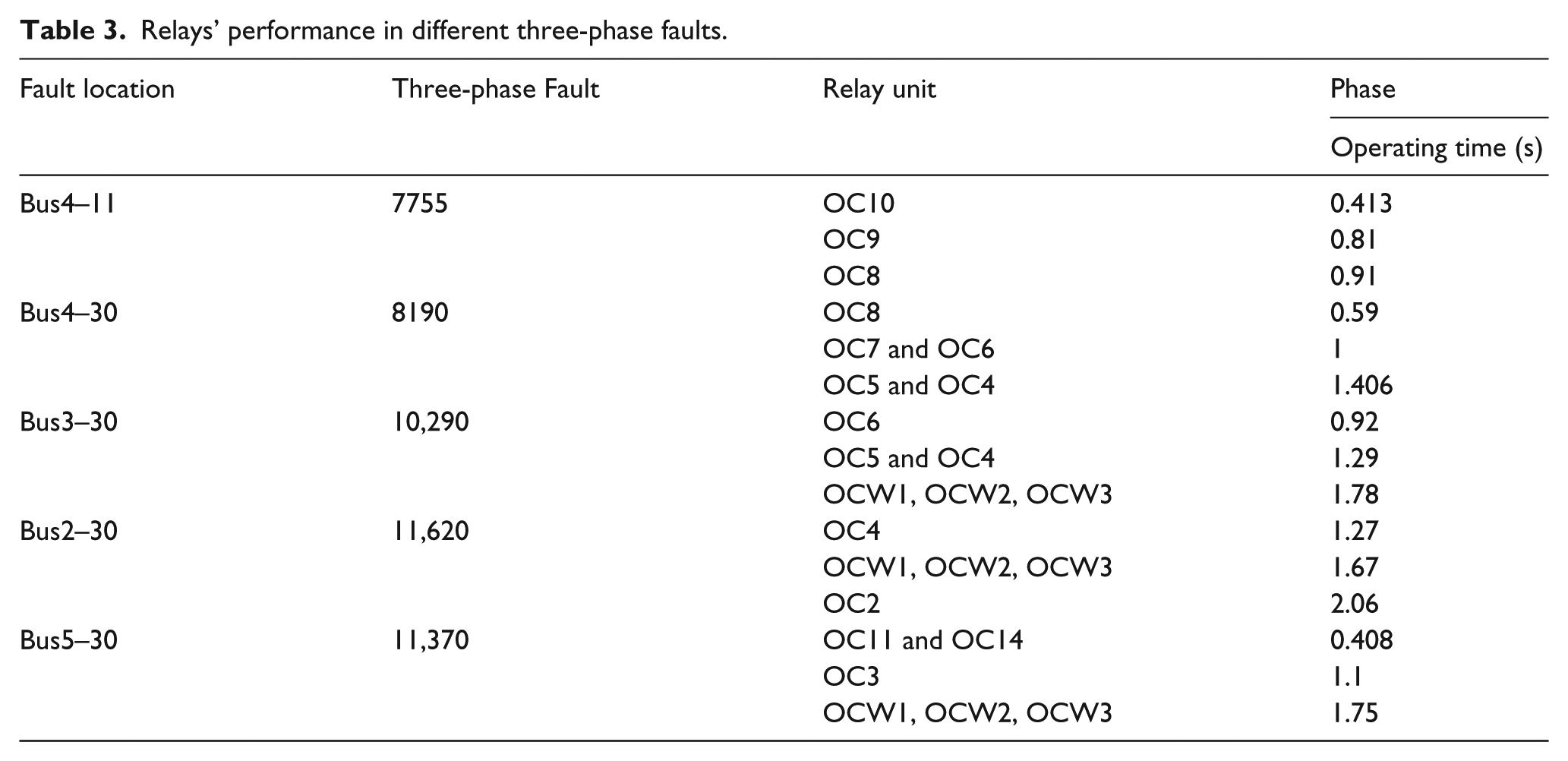
It is noticeable from Table 3 that the operating time for the relays in almost all the fault locations exceed 1.00 s; this is due to the time margin provided by the operator for the low-voltage protective devices to activate and isolate faults to avoid false tripping in healthy feeders; the operating time for relays OC10, OC9, and OC8 in case of fault on Bus4–11 elucidates the time margin (CTI) allowed for the overcurrent protection of the low-voltage side to clear fault when occurring on 11-kV busbars, which is almost 1.79 s. In the case of three-phase fault on Bus2–30, it is recognizable that the current value contributed by the main feeder is constant even when RDG is connected to the grid; this is because the impedance to the location of the fault shown by the main feeder remains the same.
Figure 7 shows the TMS of relays OC9 and OC10 during a fault on Bus4–11; it gives observation of the response of those relays in case of a three-phase fault. The operating time for OC5 before connecting RDG is 0.408 s. it can be seen that the operating time for the OCRs remains constant after interconnecting RDG for three-phase fault and ensures the selectivity and reliability of the protection coordination for the DN.
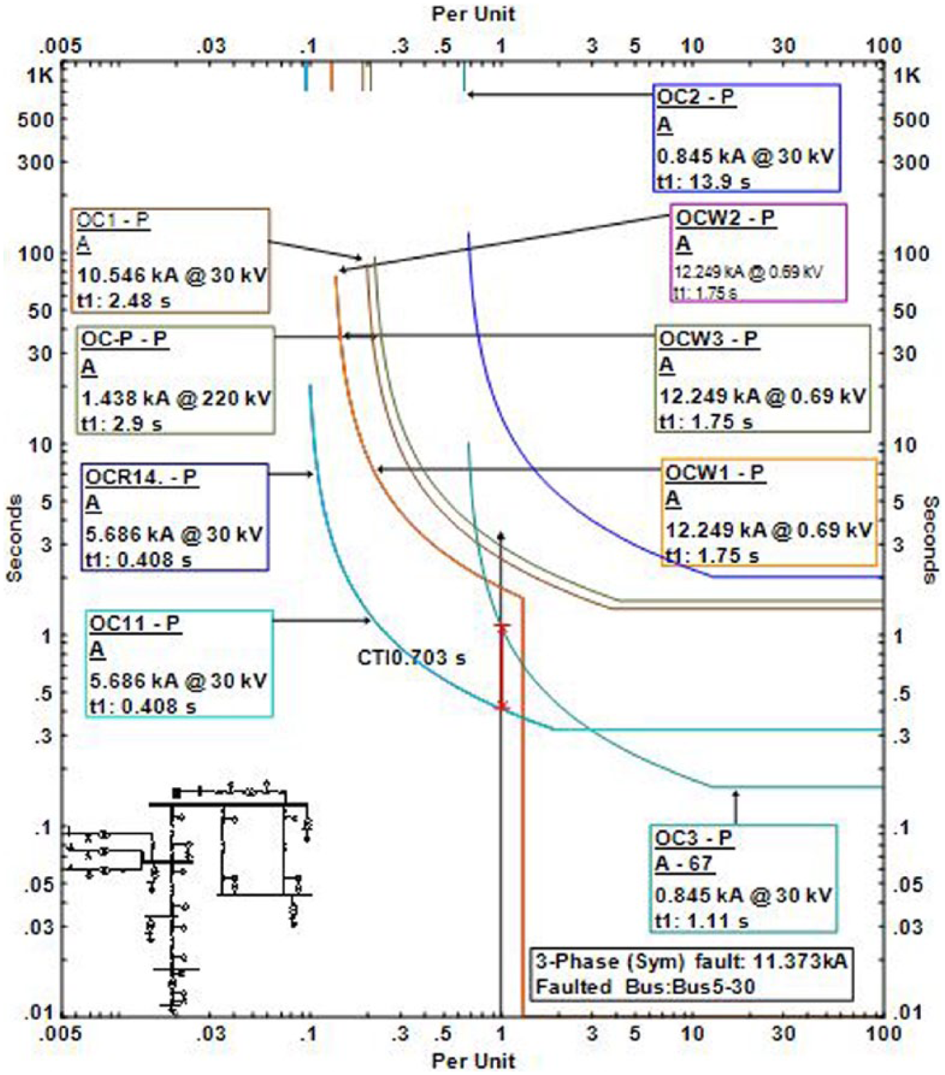
Relay characteristics in case of three-phase fault on Bus5–30.
Negative sequence overcurrent element applied for single-phase fault in DN
In the case of a single line to ground fault, negative sequence OCRs provide fast response and increased selectivity compared to the phase OCRs. Nowadays, digital relays provide negative sequence element together with phase overcurrent element without the need for adjustment in the protection system. The negative sequence element is responsible for calculating the negative sequence component in the fault current in case of unbalanced faults. The advantage of adding negative sequence scheme is the immunity of negative sequence element by load current impact, which raises the selectivity of the protection system.
The penetration of RDG into the DN can be described in terms of bi-directional power flow, and the influence becomes noticeable when a line to ground fault occurs in the secondary of transformer connecting RDG. In the presence of RDG units, the selectivity and sensitivity become compromised if optimum coordination is not acquired. From Table 4, the operating time for both negative sequence OCR and phase OCRs is tabulated. In case of single line to ground fault, the performance of negative sequence element becomes more accurate compared to phase overcurrent element.
Relays’ performance in different single-phase faults.
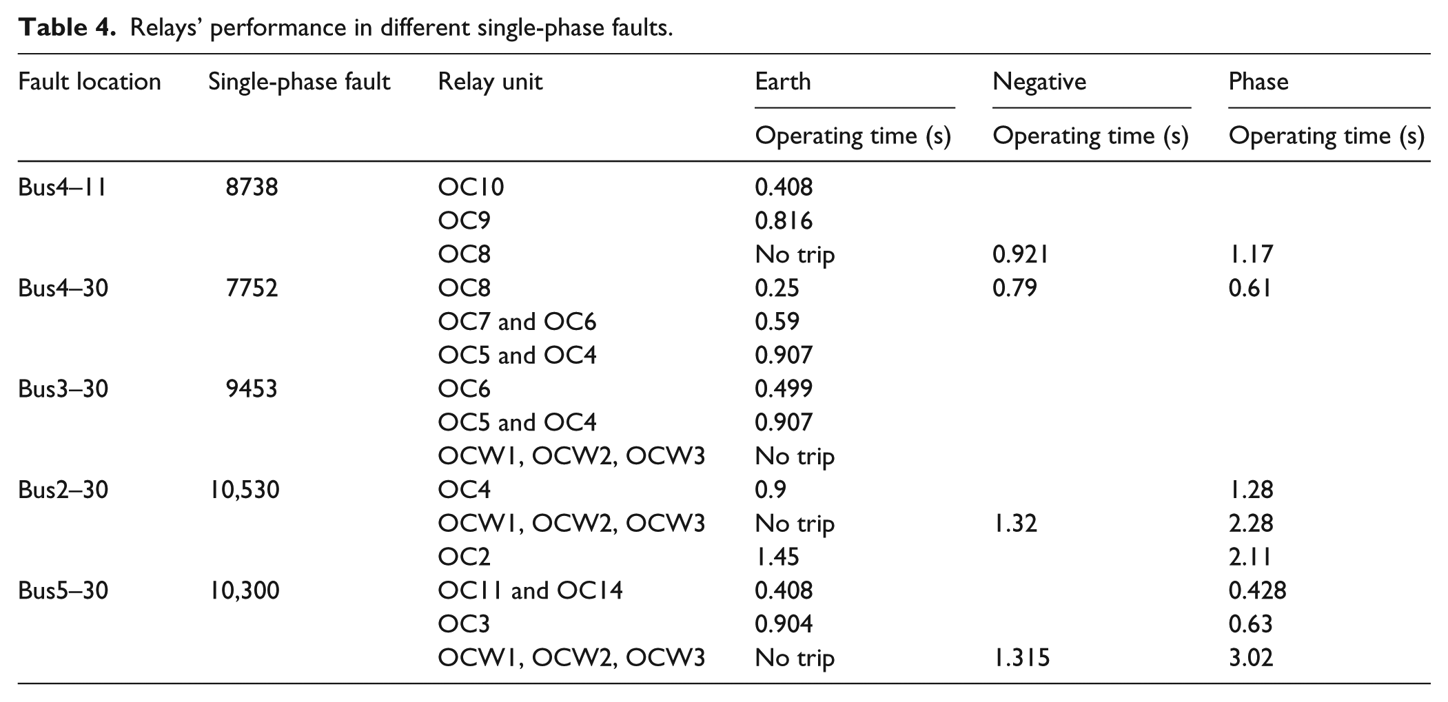
Figure 8(a) shows the time characteristic and operating time for earth element of relays OC2 and OC4. Figure 8(b) shows the time characteristic of phase and negative overcurrent element for relays OC2, OC4, OCW1, OCW2, and OW3 and the operating time for each of those relays for a single line to ground fault at busbar 2-30. The operating time for earth overcurrent element of relay OC4 is 0.9 s since it is the primary protection for a single line to ground fault at Bus2–30, and earth element of OCR OC2 operates in 1.45 s, which is considered to be the correct operating time. For OCRs OCW1, OCW2, and OCW3, detecting single line to ground fault on the secondary of transformer would be complicated for the earth elements, since the delta connection in delta–wye transformer suppresses the zero sequence components in the fault current and eventually causes maloperation of wind DG protection; while delaying the operating time for the phase element compared to the negative sequence element introduced in OCRs, negative sequence element of relays OCW1, OCW2, and OCW3 detects and trips the faulty current in 1.32 s while phase overcurrent element detects the fault current in 2.28 s, which communized CTI by 0.836 s and maintained the supply for Bus2–11 since negative sequence element of relay OC4 trips before earth element of relay OC2 and ensures the selectivity and reliability of the protection coordination for the DN.
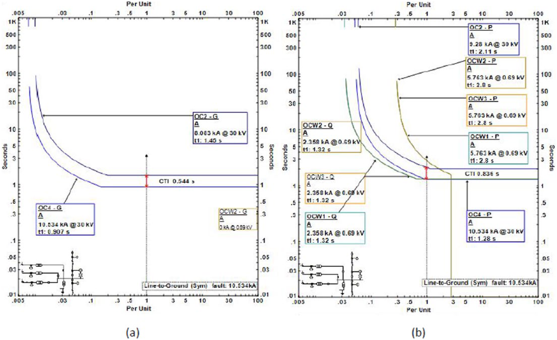
Time characteristics of relays OC2, OC4, OCW1, OCW2, and OCW3: (a) earth overcurrent element and (b) negative and phase overcurrent element in case of single line to ground fault at Bus2–30.
Figure 9(a) shows the time characteristic and operating time for earth element of relays OC8, OC9, and OC10. Figure 9(b) shows the time characteristic of phase and negative overcurrent element for relays OC8 and OC9. In case of single line to ground fault at Bus4–11, earth element of OCRs will detect the increase in the zero component as a short-circuit current, while phase element of relay OC8 will not detect the fault current on the secondary of transformer due to the configuration of distribution transformer which eliminates zero component and causes maloperation in the protection coordination, then the phase element of relay OC8 will detect and isolate the faulty current after 1.17 s, as shown in Figure 9(b); after activating negative sequence element in relay OC8, the relay will isolate the fault after 0.921 s and save 0.249 s.
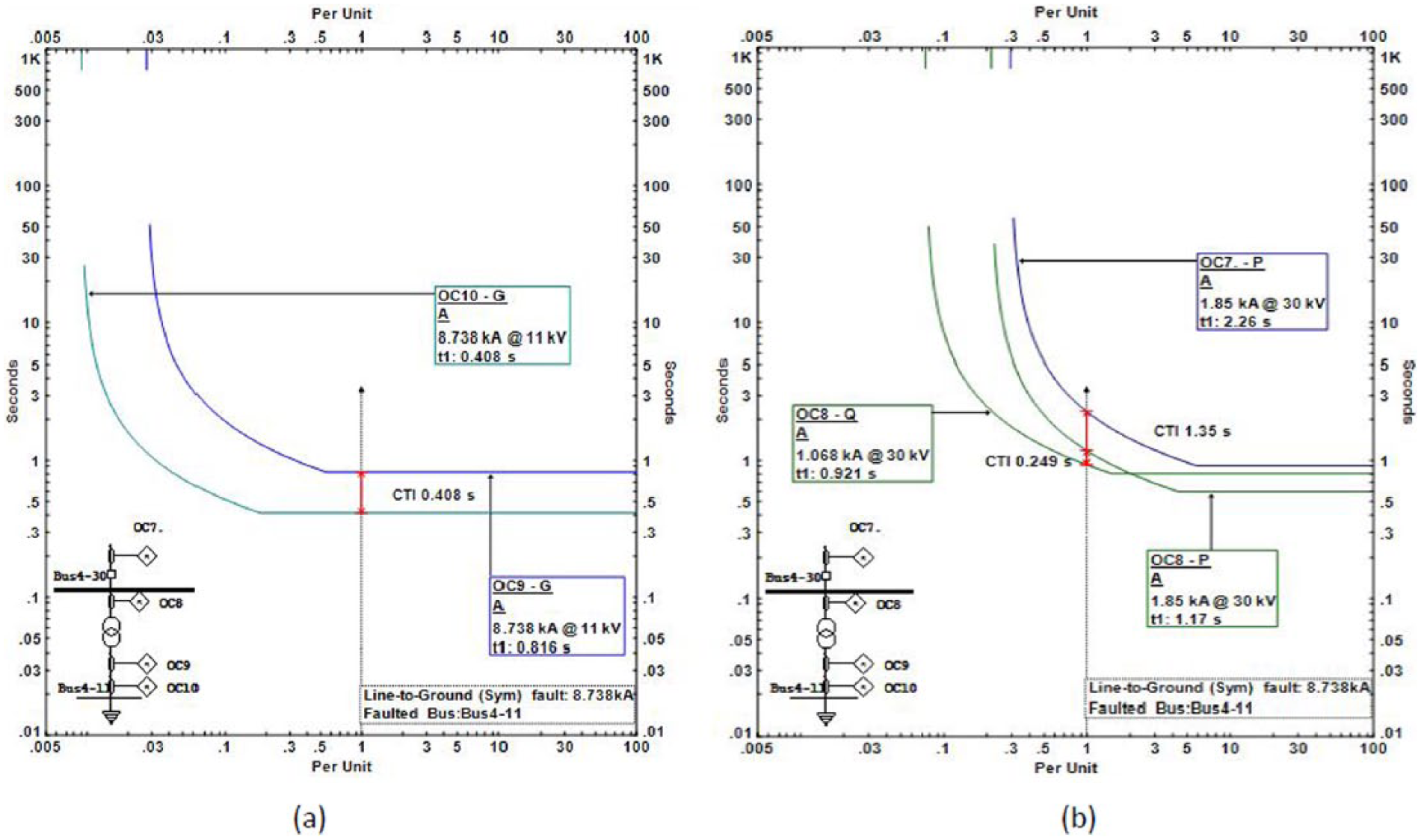
Time characteristics of relays OC8, OC9, and OC10: (a) earth overcurrent element and (b) negative and phase overcurrent element in case of single line to ground fault at Bus4–11.
Conclusion
In this study, implementation of the medium-voltage DN is presented, and a methodology used to calculate and analyze phase shifts and sequence network to study the behavior of the DN with renewable energy sources is presented. Employment of adaptive protection scheme based on activating negative sequence overcurrent protection to enhance the protection system selectivity and reliability had been established.
A comparative study of the negative sequence relay against phase OCR in different transient operating conditions has been carried out. Negative sequence OCRs provide better coverage for ground faults and increase the sensitivity of the protection system; insensitivity of negative sequence relays to loading current increases the time response for heavily faulted current due to the low magnitude of the negative component of load current.
Further study and investigation of the influence of phase-to-phase faults and double line to ground fault on the protection coordination of DN protection is needed. Employment of artificial intelligence techniques for online optimization and the adaptive scheme would enhance the performance of protection system with penetration of wind DG in the network.
Footnotes
Declaration of conflicting interests
The author(s) declared no potential conflicts of interest with respect to the research, authorship, and/or publication of this article.
Funding
The author(s) received no financial support for the research, authorship, and/or publication of this article.