
Abstract
Among the issues of floating offshore wind turbines are the platform-pitching vibrations generated by blade pitch angle motions of the variable speed control. Control of blade pitch angle based on the platform-pitching motion (floating platform vibration control) can suppress these vibrations. This study investigates the impact of floating platform vibration control on variable speed control and the generator torque control, which control interferences cause the fluctuation of generator speed and platform-pitching angle at the transition region between below and above rated operating conditions. This study also proposes a new control to reduce the impact; in this method, the lower limit of generator torque is adjusted linearly depending on the nacelle wind speed, and the conventional feedback control for the generator torque mainly adjusts the generator torque. Simulation and demonstration results using a full-scale spar-type FOWT showed that the proposed method can stabalize suppress the fluctuations of generator speed, platform-pitching angle, and power at the transition region.
Introduction
Wind power generation is becoming widely used globally because of its low environmental impact and also because it can increase the levels of both energy security and energy independence; it is forecast that the installation of wind power will increase continuously from now on. The Global Wind Energy Council (GWEC, 2017) reports that the cumulative wind capacity reached 539 GW at the end of 2017. WindEurope (2017) expects that 50 GW will be installed in the 4 years between 2017 and 2020, and the expected cumulative installed capacity by 2020 will amount to 204 GW.
Most wind turbines have been installed at onshore sites; however, the installation of offshore wind turbines has also been spreading. GWEC (2017) reports that the cumulative capacity of offshore wind reached 18.8 GW at the end of 2017, which amounts to over 40 times that of 2011. Almost all of these offshore wind turbines are the bottom-fixed type. In contrast, floating offshore wind turbines (FOWTs) are expected to be installed because they can be installed far from the coast and can utilize stronger and more stable wind power than near the coast.
Because the supporting structures (floating platforms) of FOWTs are not rigidly fixed to the seabed, they tend to change their postures compared with the bottom-fixed type of wind turbines. Larsen and Hanson (2007) have reported a low-frequency vibration when the FOWT operates within the rated conditions. This vibration is caused by variable speed control (VSC). VSC adjusts the blade pitch angle (BPA) to keep the rotor speed around a reference speed above the rated operating conditions; however, the BPA motion changes the thrust force applied to the rotor, and this change in thrust force amplifies the platform-pitching vibration of the FOWT. This vibration increases the fatigue loads. Therefore, the vibration in FOWTs needs to be suppressed.
Several studies have been conducted to suppress the platform-pitching vibrations. These studies are related to control methods and are mainly divided into two types: one is using only BPA and the other is using both BPA and generator torque.
The studies on BPA control are as follows. Skaare et al. (2007) proposed a BPA control to suppress the platform-pitching vibrations and showed that it could stabilize the platform posture by generating a damping property for the platform-pitching motion. Bagherieh et al. (2014) proposed two types of controls, an input/output feedback control and a sliding control, to reduce fluctuations of both the rotor speed and the platform-pitching motion, and showed that the latter could satisfy both fluctuations. Jonkman (2008) proposed three control methods to reduce platform-pitching vibrations: a BPA control based on nacelle acceleration, a stall control, and a VSC with low control gains. The simulation results showed that the third control method was better but had limited effectiveness. Guo et al. (2012) proposed an expert proportional-integral-derivative (PID) control that changes its control gains according to the difference between the measured and target signals. The expert PID also has a function of adjusting the BPAs independently based on the d–q transform of the rotor angle. They show that it can stabilize both the output power and the platform-pitching motion.
Studies on utilizing both BPA and generator torque are as follows. Betti et al. (2012) devised a two-dimensional (2D) FOWT model with a spar platform and proposed an H∞ control to stabilize the platform-pitching motion. They reported that their proposed method could suppress the platform-pitching vibrations. Larsen and Hanson (2007) proposed some countermeasures against the platform-pitching vibrations and stated that a VSC gain-tuning method applied to bottom-fixed wind turbines reduces the output power fluctuation but cannot suppress the platform-pitching vibrations, and that a method based on stall control can stabilize both output power and pitching motion. Christiansen et al. (2012) proposed a linear quadratic regulator (LQR) control that minimizes the rotor thrust force by reducing the rated speed more than the rated wind speed. Although it can suppress the platform-pitching vibrations, it increases the roll angle of the floating platform. Therefore, they concluded that the proposed control should be combined with a conventional VSC. Christiansen et al. (2011) focused on FOWTs with spar platforms and proposed an LQR control based on an observer that predicts rotor angle and tower deflection. The proposed method controls the BPA and the generator torque, and it can not only reduce fatigue Damage Equivalent Loads (DELs) but also stabilize the output power.
These studies are effective in suppressing the platform-pitching vibrations; however, some studies report that the controls used to suppress the vibrations have impacts on FOWTs. Kakita et al. (2015) proposed a collective BPA control based on proportional-integral (PI) control in which a fictitious reference interactive tuning (FRIT) method changes the gains of the PI controller. They noted that the proposed control could suppress the fluctuations in rotor speed and platform-pitching motion under variable wind speed conditions; however, the performance of the BPA rate deteriorated by a factor of three over that without using the proposed method. Namik and Stol (2014) compared the performance of three control strategies: state feedback control (SFC), disturbance-accommodating control (DAC), and gain scheduling PI (GSPI, a baseline) control. They concluded that the SFC deteriorates fatigue in low-speed shafts with reducing tower fore–aft bending fatigue, that the DAC can reduce rotor speed variation, although both control methods increase the blade pitch system loads.
Kakuya et al. (2017) have reported a BPA control for suppressing the platform-pitching vibrations (floating platform vibration control (FVC)) that has a mode-change function based on the output power, and we showed experimental results by using a full-scale 2 MW demonstration FOWT with a hybrid spar-floating platform and showed that FVC can suppress the platform-pitching vibrations not only at rated operating conditions but also below them. However, we subsequently confirmed that at wind speed in the range of ~10 m/s, the platform-pitching vibrations were not suppressed sufficiently. This wind speed range is the same as the transition region between below and above rated operating conditions. In this work, we propose a control method for suppressing the platform-pitching vibrations in the transition region that controls the lower limit of the generator torque. The method is based on the nacelle wind speed measured by a wind speed sensor placed at the top of the nacelle. In addition, we investigate the validity of the present method using a full-scale FOWT, although the above-mentioned studies mainly showed those validities using simulations.
In the “Impacts of FVC on FOWTs” section, we clarify the reason for the platform-pitching vibration in the transition region. In the “Generator torque lower limit control based on nacelle wind speed” section, we propose the generator torque control (GTC) along with its schematic control algorithm. In the “Demonstration apparatus” section, we describe the specifications of a demonstration apparatus. In the “Simulation results” section, we show some simulation results comparing the results obtained with and without the proposed control. In the “Demonstration results” section, we present demonstration results in the transition region using the full-scale FOWT. Finally, the “Conclusion” section concludes the study.
Impacts of FVC on FOWTs
In this section, we clarify the platform-pitching vibration of FOWTs in the transition region. Bottom-fixed wind turbines have VSC and GTC to control the rotor speed and the output power, but FOWTs also have FVC for suppressing the platform-pitching vibrations. In this section, we describe the impact of FVC on the controls of wind turbines.
Control interference of VSC and FVC
A schematic representation of a BPA control for FOWTs is shown in Figure 1. VSC generates the BPA demand based on the difference between the measured and reference generator speed and FVC generates the BPA demand based on the nacelle pitch angle, and the final BPA demand is given by adding these two BPA demands (Figure 1). These two controls determining the BPA demands are feedback controls and they independently determine each BPA demand because not only their input signals but also the purpose of each feedback control is different. If each feedback control adjusts each BPA demand independently, the BPA demand of one controller can cancel the BPA demand of the other controller; that is, control interference can occur. The solid red line in Figure 2 shows the path of this interference.
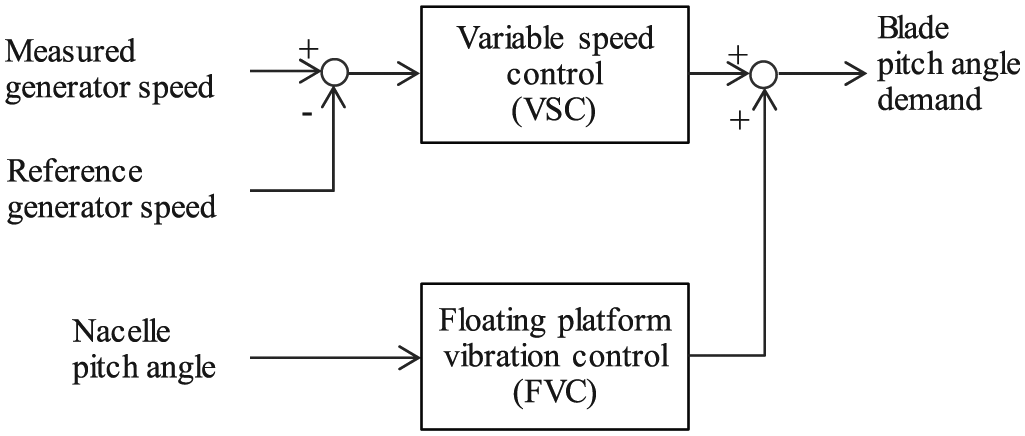
BPA control for FOWTs.
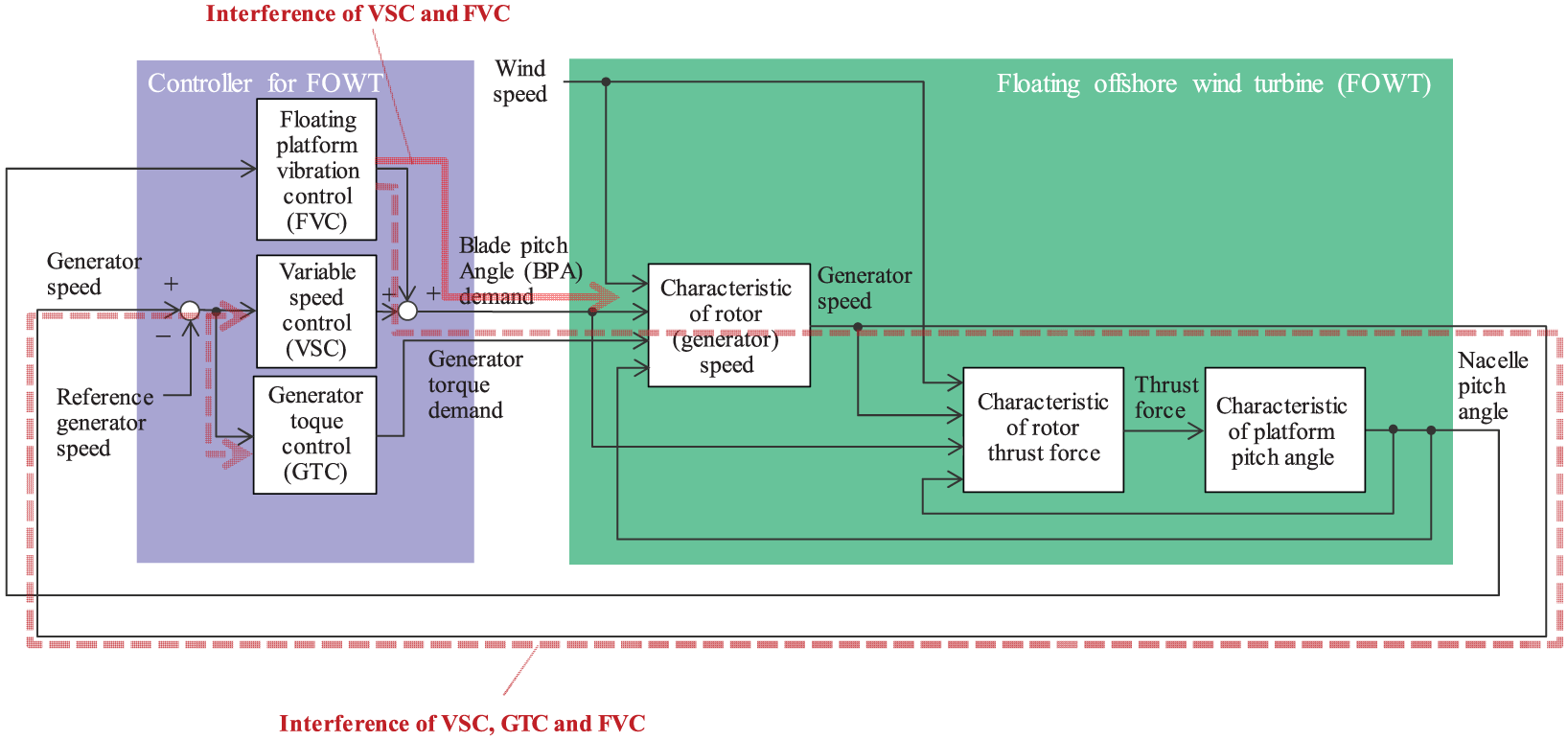
Schematic of whole system (FOWT and controller).
One countermeasure against the above-mentioned control interference is making feedback gains high. However, setting high-feedback gains tends to fluctuate the BPA demands of the feedback controls and it can take a longer period to converge the BPA fluctuations. This fluctuation of BPA can vary the rotor thrust force and then the platform-pitching vibrations occur.
Control interference of VSC, GTC, and FVC
A schematic representation of GTC is shown in Figure 3. Similar to VSC in Figure 1, GTC is a feedback control and generates the generator torque demand based on the difference between the measured and reference generator speeds. Figure 4 shows the steady characteristics of the wind turbine, electrical power, and generator speed. In the transition region between below and above rated operating conditions, at middle wind speed in the range of

GTC.
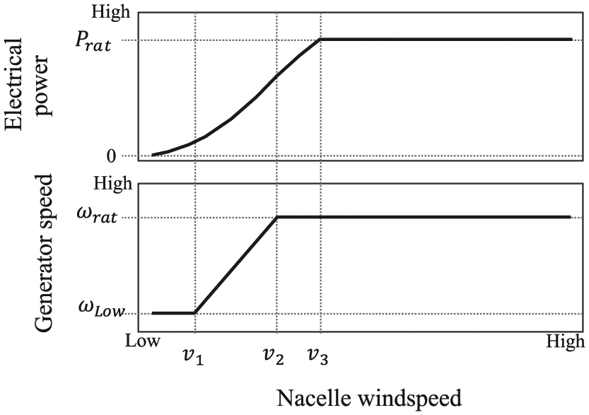
Steady characteristics of FOWT.
As mentioned above, the FVC modifies the BPA. The change in BPA given by FVC varies the generator speed. As the input of GTC is generated by the generator speed, the demand of FVC can cause the output of GTC to fluctuate. Furthermore, the demand of FVC can also cause the output of VSC to fluctuate because the input of VSC is also given by the generator speed. The output fluctuations of VSC and GTC can cause the generator speed to fluctuate because the outputs of VSC and GTC (BPA and generator torque demands) determine the generator speed. Therefore, FVC can cause a deterioration in the performance of VSC and GTC and can magnify the fluctuation of the generator speed. At last, the generator speed fluctuation leads to the platform-pitching vibration because the generator speed is one of the factors determining the rotor thrust force, that is, a control interference of VSC, GTC, and FVC occurs (Figure 2). The broken red line in Figure 2 shows the path of this interference of VSC, GTC, and FVC. Of course, the unique characteristics, namely, the platform-pitching angle of FOWTs is easy to change and the fluctuation of the platform-pitching angle leads to the fluctuation of relative wind speed, are also the factors to generate the fluctuation of the generator speed.
Although FVC causes both the fluctuation of the generator speed and the control interferences, the variance of the wind speed can also become a source of generator speed fluctuation because wind speed is one of the factors determining the generator speed (see Figure 2). Therefore, the wind speed variance can cause the control interference.
We stated above that an example of countermeasures against these interferences is setting high-feedback gains. However, large numbers of feedback gains need to be optimized to reduce the interference impacts when there are many controls related to the interferences, and many operational and environmental conditions need to be adapted.
This section can be summarized as follows:
FVC can cause control interference with VSC.
FVC can also cause control interference with VSC and GTC.
The control interference causes fluctuation of the generator speed, which is one of the input signals of VSC and GTC.
The fluctuation of the generator torque generates the platform-pitching vibration.
The wind speed variance can also cause a fluctuation of the generator speed because it is one of the factors determining the generator speed.
Generator torque lower limit control based on nacelle wind speed
In this work, we propose a new method for suppressing the interference impacts in the transition region, in which the generator torque is controlled depending on the nacelle wind speed; the method is an alternative to using high-feedback gains.
Example equations for GTC at a nacelle wind speed in the range of


where
Assuming that the drivetrain of the FOWT, which consists of the rotor, gearbox, and generator, has a rigid characteristic, equation (6) is obtained

where
The relation between the generator speed and the rotor speed is given by

Equations (1), (6), and (7) give the next equation

The Laplace transform of equation (8) is given as follows

equation (9) shows that the rotor torque converted by wind energy varies with the rotor speed. Conversely, applying the rotor torque can control the rotor speed. Because one of the control interferences by FVC can cause fluctuation of the generator speed, reducing the latter fluctuation can suppress the control interference. Considering these points, to suppress the generator torque we assume a method of actively controlling this torque. The assumed method is given by converting equation (1) as follows

where
Using equations (6), (7), and (10), we can obtain the next equation similar to equation (9)

equation (11) indicates that equating the rotor torque

In this work, we approximate the transfer characteristic of the rotor torque


where
The proposed method defines a linear equation of the nacelle wind speed and a first-order time-lag as a transfer function of the rotor torque qF and the rotor wind speed vr


where TF is a time constant of the proposed method, Aq is a slope of the linear equation (15) for calculating the rotor torque qF by the rotor wind speed vr, Bq is the intercept of the linear equation (15), and qF is the rotor torque gain given by the nacelle wind speed v. Because of the interference with the rotor motions, the nacelle wind speed v is unreliable if the values measured by the wind speed sensor placed at the nacelle are used directly. However, the proposed method can reduce the interference by using the first-order time-lag filter, as shown in equation (16). Some alternative sensors, for example, laser imaging detection and ranging (LIDAR) system, are also acceptable for measuring the nacelle wind speed. However, the measured values need to include information of the wind speed generated by the platform motions because the proposed method requires the information of wind speed flowing into the rotor to control the generator torque.
We define the linear equation as the relation of


where
The proposed method controls the generator torque by using the feedback control described in equation (1) with changing the lower generator torque limit depending on the nacelle wind speed. The proposed method controls
The difference between the generator torque values without and with the proposed method is shown in Figure 5. Without the proposed method, the generator torque can change within the square area; with the proposed method, it can change within the triangular area.
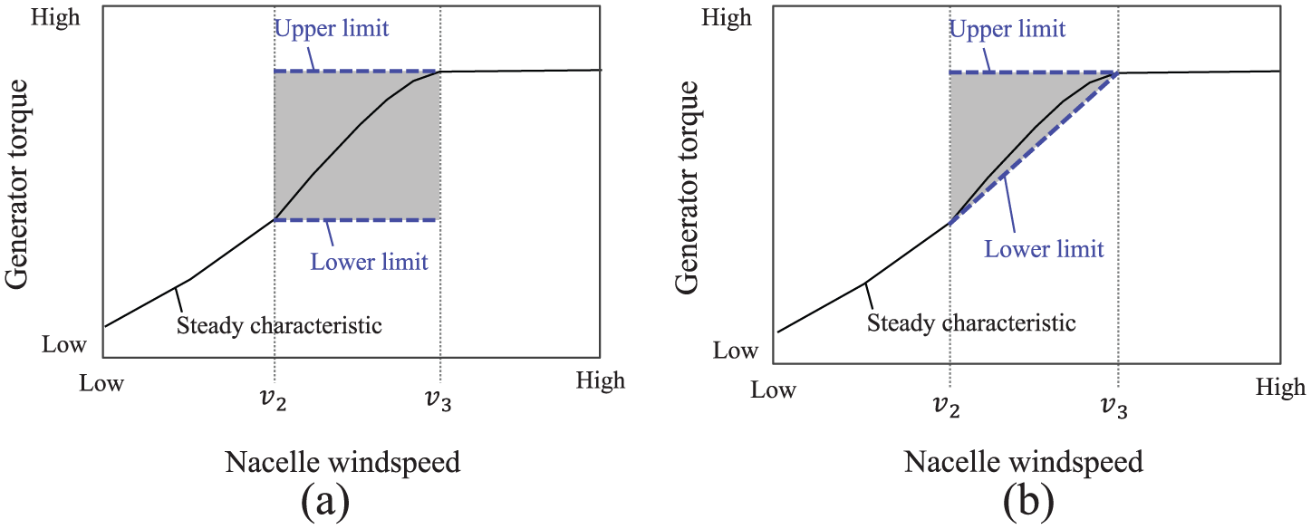
Difference in GTC: (a) without the proposed method and (b) with the proposed method.
Demonstration apparatus
The demonstration apparatus we used is shown in Figure 6. This apparatus was constructed originally for the GOTO Floating Offshore Wind Turbine Demonstration Project, funded by the Ministry of Environment (MOE), Japan. Its specifications are shown in Table 1. The spar-type floating platform has a hybrid station-keeping structure: the upper side is made of steel and the lower side is made of prestressed concrete.

FOWT demonstration apparatus, originally part of the MOE project (Utsunomiya et al., 2015).
Specifications of FOWT (Utsunomiya et al., 2015).
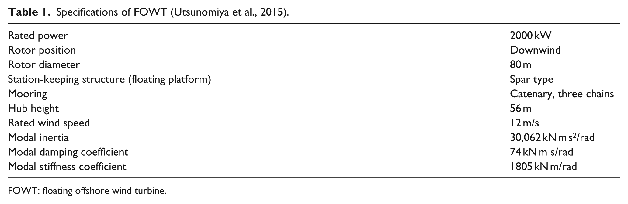
FOWT: floating offshore wind turbine.
Simulation results
We evaluated the performance of suppressing the floating platform-pitching vibration about the following four items:
dynamic responses,
steady characteristics,
maximum loads,
damage equivalent fatigue load.
The parameters of the proposed method for simulations are listed in Tables 2 and 3. The sea states of wave height and wave periods are set to the site-specific values depending on wind speed.
Simulation conditions of dynamic responses.
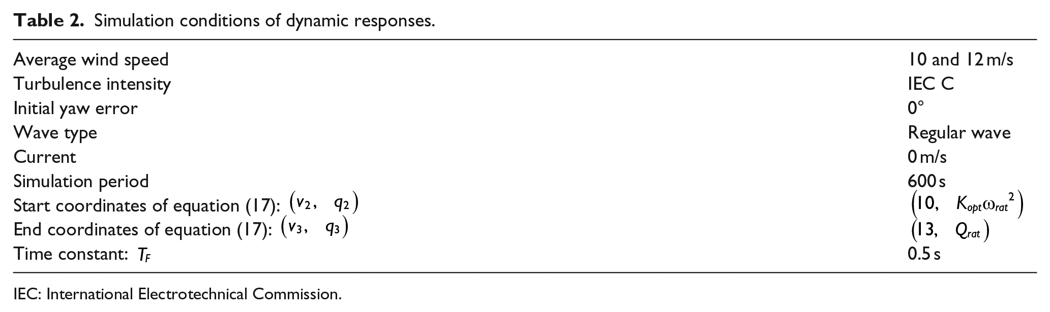
IEC: International Electrotechnical Commission.
Simulation conditions of steady characteristics.

IEC: International Electrotechnical Commission.
Dynamic responses
The simulation results of dynamic responses are shown in Figure 7 at an average wind speed of 10 m/s. Note that a backward direction of floating platform-pitching motion indicates a plus sign direction of floating platform-pitching angle. In Figure 7, dotted lines are results without the proposed method and solid lines are results with it.
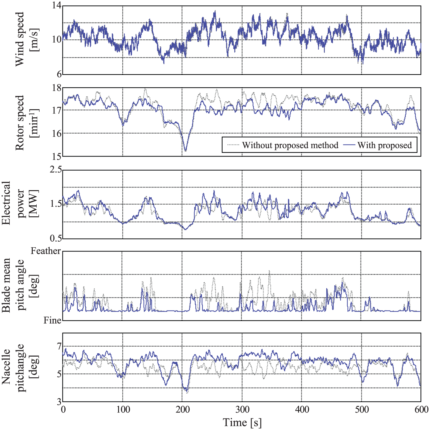
Simulation results: time-series data at an average wind speed of 10 m/s and an initial yaw error of 0°.
As shown by the dotted line in Figure 7, without the proposed method, rotor speed, BPA, and nacelle pitch angle (platform-pitching angle) fluctuate at the time of 220 to 380 s. It is clear that fluctuation of electrical power also occurs. As mentioned above, the control interferences or the variance of wind speed can generate those fluctuations. In contrast, the solid lines in Figure 7 show that those fluctuations are suppressed during the same period, especially the nacelle pitch angles are more stable than without the proposed method.
The power spectral densities (PSDs) of the dynamic responses are shown in Figure 8. The dotted lines in Figure 8 show that PSDs of rotor speed, electrical power, blade mean pitch angle, and nacelle pitch angle (platform-pitching angle) have peaks around 0.05 Hz. As the natural frequency of the platform-pitching angle is 0.039 Hz, these peaks can be generated by the control interference stated above. It is clear that the solid lines do not have those peaks around 0.05 Hz. Therefore, the simulation results demonstrate that the proposed method can suppress the impacts of FVC at the average wind speed of 10 m/s.
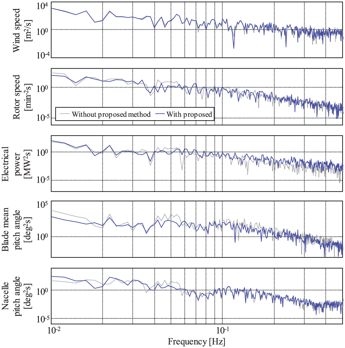
Simulation results: power spectral density at an average wind speed of 10 m/s and an initial yaw error of 0°.
The simulation results of dynamic responses are shown in Figure 9 for an average wind speed of 12 m/s. As shown by the dotted line in Figure 9, without the proposed method, the fluctuations of rotor speed and nacelle pitch angle (platform-pitching angle) continue between 220 and 480 s. The solid lines in Figure 9 show that these fluctuations are reduced. The electrical power with the proposed method is higher than that without the proposed method between 220 and 270 s, because the proposed method can suppress the above-mentioned control interferences.
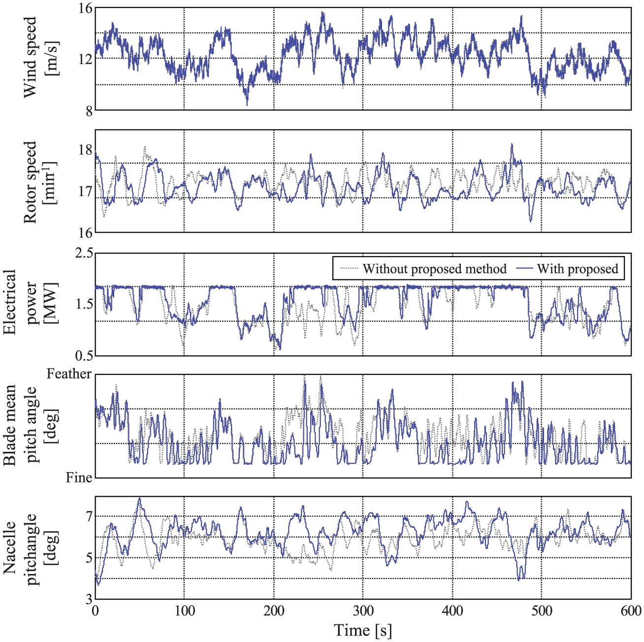
Simulation results: time-series data at an average wind speed of 12 m/s and an initial yaw error of −8°.
The PSDs of the dynamic responses of Figure 9 are shown in Figure 10. The dotted lines in Figure 10 show that the PSDs of rotor speed, power, blade mean pitch angle, and nacelle pitch angle (platform-pitching angle) have peaks around 0.04 Hz. As these peaks are similar to the natural frequency of the platform-pitching angle of 0.039 Hz, these peaks can be amplified by the control interference stated above. It is clear that those peaks around 0.04 Hz of the solid lines decrease. Therefore, these simulation results also demonstrate that the proposed method can suppress the impacts of FVC at an average wind speed of 12 m/s.
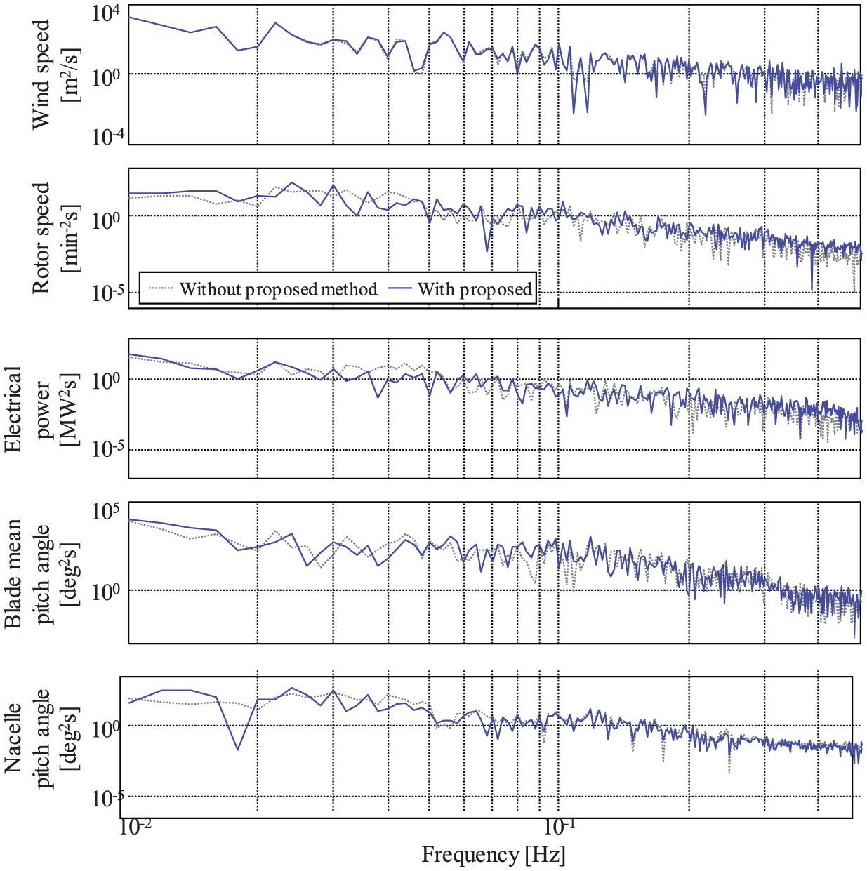
Simulation results: power spectral density at an average wind speed of 12 m/s and an initial yaw error of −8°.
Steady characteristics
The steady characteristics of changing rate of cumulative moving distance of BPA, average electrical power, and average platform-pitching angle given by the proposed method are shown in Figure 11. The baselines are simulation results without the proposed method. These simulation results are averages of the yaw angles of −8°, 0°, and 8°, at each average wind speed.

Simulation results—steady characteristics of the changing rate by the proposed method: (a) average platform pitch angle, (b) average electrical power, and (c) cumulative moving distance of BPA.
The average of the nacelle pitch angles (platform-pitching angles) at each average wind speed increases at wind speeds in the range of 8 to 14 m/s (Figure 11(a)). This is because the proposed method suppresses the fluctuation of rotor speed (generator speed) because this is one of the factors determining the thrust force. By suppressing the fluctuations of the platform-pitching angles, wind energy is not consumed for changing the platform-pitching angle and much more wind energy is caught by the rotor. Therefore, the thrust force increases.
The electrical power increases up to 3.4% at wind speeds in the range of 10 to 16 m/s (Figure 11(b)). This is related with the results of Figure 11(a). As mentioned, the proposed method can increase the wind energy that the rotor can catch. The increase in wind energy also increases not only the thrust force of the rotor but also its power efficiency.
It is clear in Figure 11(c) that the cumulative moving distances of BPA with the proposed method improve and the maximum improvement is up to 43%. These improvements are given by the effect of the proposed method, which reduces the fluctuation of rotor speed, as mentioned. Reducing the cumulative moving distance of BPA contributes to the load reduction of the blade pitch actuator.
Extreme loads
The extreme loads without and with the proposed method are shown in Figure 12. These four loads are bending moments perpendicular to the main axis directions of each part. These extreme loads are given by the simulation results of Figure 11, which reached 30 cases (10 wind speed cases at each yaw error condition).
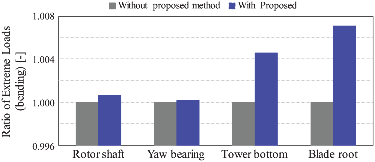
Simulation results: comparison of extreme loads.
All the extreme loads of the proposed method increase compared with those without the proposed method (Figure 12). These can be given by increasing the thrust force and the power efficiency as stated in Figure 11. The increasing rate is at most less than 0.1% and it cannot lead to much damage to the system structures and components.
Fatigue loads
The fatigue loads without and with the proposed method are shown in Figure 13. These fatigue loads are also given by the simulation results shown in Figure 11, similar to the results shown in Figure 12.
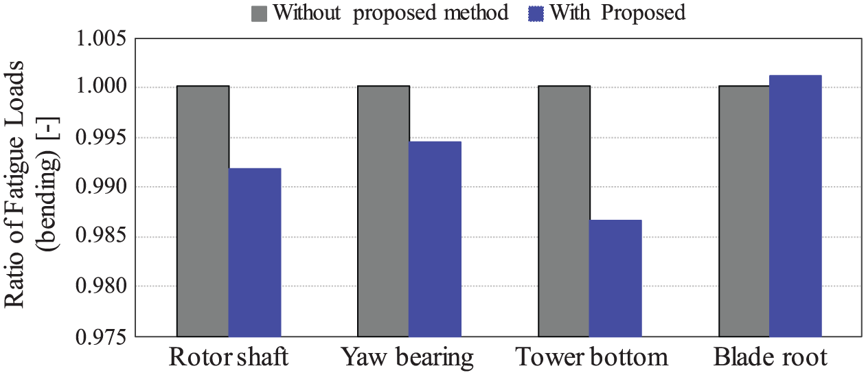
Simulation results: comparison of fatigue loads.
The fatigue loads of the rotor shaft, yaw bearing, and tower bottom with the proposed method reduce compared with the values without the proposed method (Figure 13). This is because the proposed method can suppress the fluctuations of rotor speed (generator speed) and nacelle pitch angle (platform-pitching angle). However, the fatigue load of the blade root increases. This increase can be a result of increasing the thrust force and the power efficiency, as stated in Figure 11. The increasing rate is at most 0.01% and it cannot affect the system’s tolerance.
Demonstration results
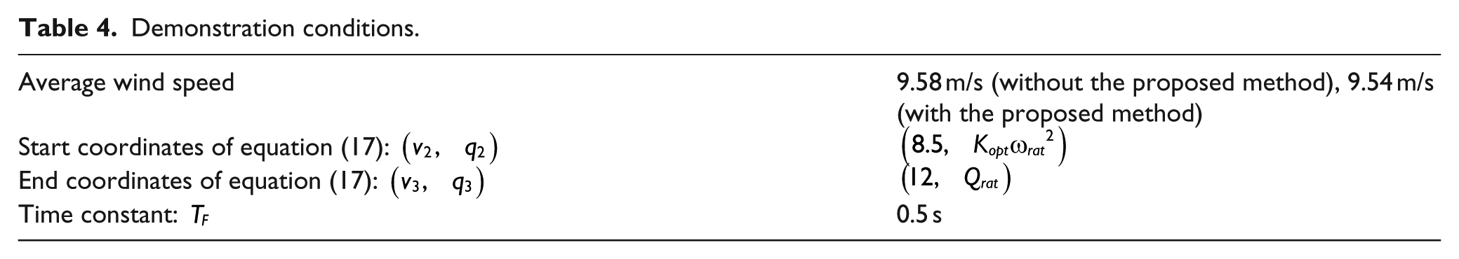
In this section, we report some demonstration results that show the validity of the proposed method by using the full-scale FOWT. Table 4 shows the demonstration conditions. The coordinates of start and end points of equation (17) are different from those in the previous section because the wind speed measured near the nacelle is lower than that at hub height. These values were determined by some trial operation results. All the periods for which demonstrations were executed without and with the proposed method were close, and each demonstration condition, average wind speed, turbulence intensity, and wave were similar.
Demonstration conditions.
The demonstration results without the proposed method are shown in Figure 14. The nacelle pitch angle (platform-pitching angle) fluctuated after a time of 100 s. Although the nacelle wind speed also fluctuates, the fluctuation is generated by the fluctuation of nacelle pitch angle and the wind speed has no similar frequency components. These fluctuation components are present in the rotor speed (generator speed), electrical power, and BPA, and these fluctuations are synchronized. These fluctuations can be caused by the increase in wind speed and rotor speed (generator speed) near the time of 80 s. As the values of VSC, GTC, and FVC operation depend on the changes in rotor speed (generator speed) and the platform-pitching angle, the control interferences occur and finally the fluctuations occur.
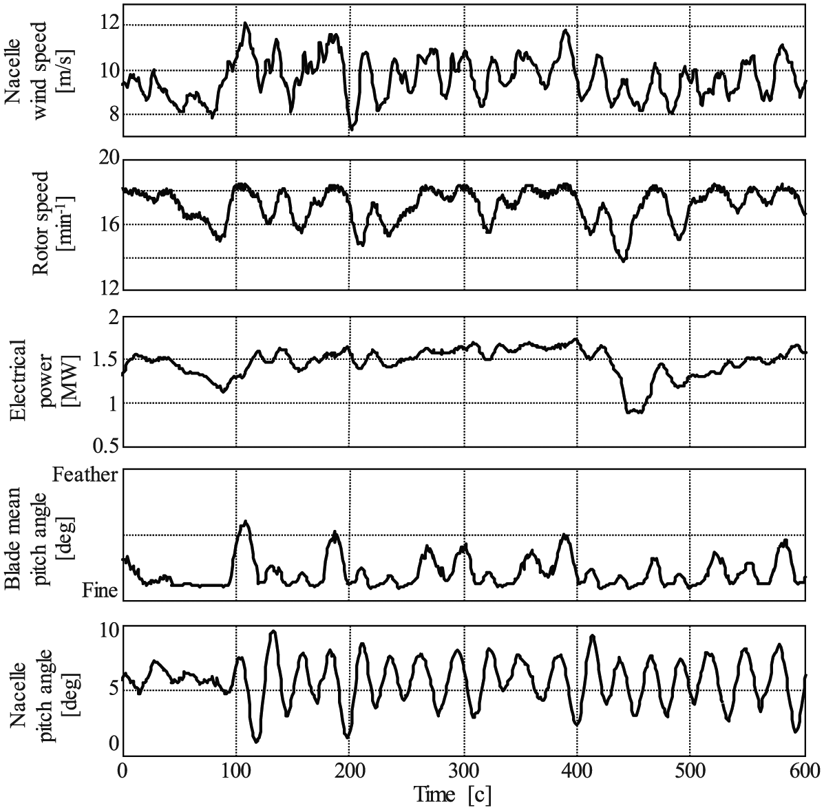
Demonstration results: time-series data at an average wind speed of 9.58 m/s. The oscillation of the nacelle pitch angle emerges at the middle wind speed range between 8 and 12 m/s.
The PSDs of the demonstration results of Figure 14 are presented in Figure 15. The PSD of the nacelle wind speed has two peaks around 0.025 and 0.035 Hz. From our experience, as there are no such peaks in natural wind speed, these peaks can be generated by the control interferences mentioned above. The other PSDs also have these two peaks. As the frequency components of 0.035 Hz are near the natural frequency of the platform-pitching angle, the frequency components of 0.025 Hz can be generated by the above-mentioned control interferences.
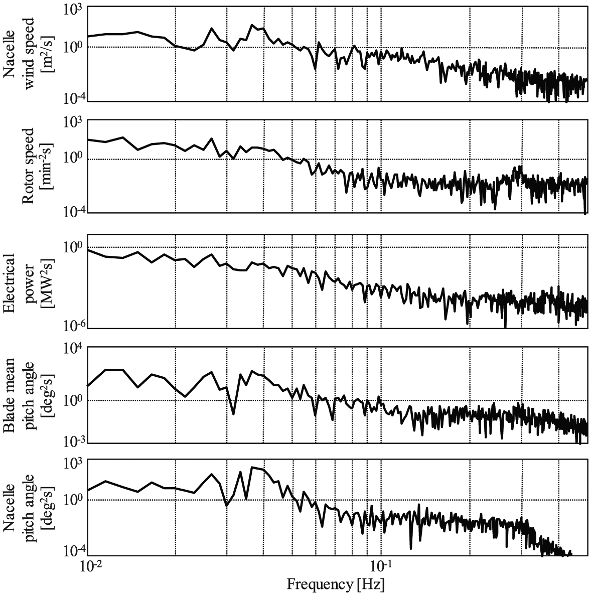
Demonstration results: power spectral density at an average wind speed of 9.58 m/s. The oscillation of the nacelle pitch angle emerged at the middle wind speed range between 8 and 12 m/s.
The demonstration results with the proposed method are shown in Figure 16. The fluctuation of nacelle pitch angle (platform-pitching angle) of Figure 14 is suppressed (Figure 16). Furthermore, the fluctuations of the rotor speed (generator speed), electrical power, and BPA are also suppressed. The PSDs of the demonstration results of Figure 16 are presented in Figure 17. It is clear that the PSDs of the two peaks around 0.025 and 0.035 Hz do not exist. From these demonstration results, the proposed method is valid for suppressing the fluctuation of the platform-pitching angle in the transition region.

Demonstration results of the proposed method: time-series data at an average wind speed of 9.54 m/s. The oscillation of the nacelle pitch angle is reduced.
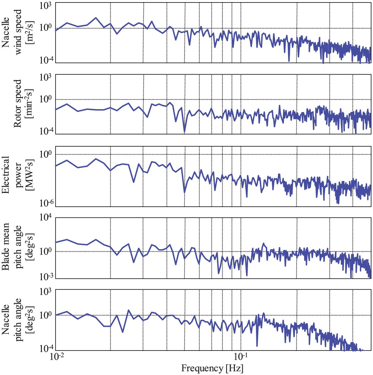
Demonstration results of the proposed method: PSD at an average wind speed of 9.54 m/s. The oscillation of the nacelle pitch angle is reduced.
Conclusion
In this article, we proposed a GTC in which the lower limit of the generator torque is adjusted linearly depending on the nacelle wind speed, to suppress floating platform-pitching vibrations in the transition region between below and above rated operating conditions, although the conventional feedback control for generator torque mainly adjusts the generator torque demand, to suppress floating platform-pitching vibrations at the middle wind speed conditions. The simulation results demonstrated that the proposed method can suppress the fluctuation of the platform-pitching angle and generator speed generated by the control interference between the VSC, GTC, and FVC. Moreover, the simulation results showed that the proposed method does not affect extreme loads and fatigue loads and that the proposed method can improve the power performance in the transition region. The results of demonstrations using a full-scale spar-type FOWT showed that the proposed method can stabilize the fluctuation of rotor speed, electrical power, BPA, and platform-pitching angle at middle wind speed.
Footnotes
Acknowledgements
We thank Ministry of Environment (MOE) and the participants for allowing us to use it.
Declaration of conflicting interests
The author(s) declared no potential conflicts of interest with respect to the research, authorship, and/or publication of this article.
Funding
The author(s) disclosed receipt of the following financial support for the research, authorship, and/or publication of this article: The demonstrations in this work were performed using the commercial-scale demonstration FOWT (floating offshore wind turbine), constructed by the GOTO Floating Offshore Wind Turbine Demonstration Project, funded by the Ministry of Environment (MOE), Japan.