




Abstract
The system of systems approach is the representation of several distributed and independent systems, for a larger and complex system. The system can be defined as interacting and interdependent components forming a complex system. System perspective considers every single stator bar as a complex system, made up of several component strands and vent tubes. Strands are interacting and interdependent in orientation, to cancel out unbalanced strand voltage and minimizing circulating current. Visualizing the electrical generator with the system approach, the issue of incorrectly aligned interdependent and interacting components of the system has been noticed. The study presents the effective flux calculation due to strand tilt, and a nondestructive testing technique to measure the strand tilt. This paper first time presents a unique system perspective of the electrical generator; this would open further dimensions of system research, in electrical rotatory machinery and beyond.
1. Introduction
Losses in the generator system have been already widely discussed in previous researches, for example, iron loss, eddy loss, copper loss, windage loss. In this research, system of three-phase windings is considered as a system of three systems. Each phase is further considered as a system of several stator bar systems. Stator bar is considered a single system that is made up of several interacting and interdependent components that is, copper strands. System as presented in Figure 1 generates a different level of understanding, that is, how an individual interconnected and interdependent component of the system is contributing towards the generator system’s overall performance. Each system of stator bar is a collection of several layers of mutually transposed and conducting strands. Eddy current losses can be minimized by such arrangement (Fujita et al., 2005). In Figure 1, each stator bar is represented as a system made up of several interdependent strands. The collaborative effect of all component gives rise to improve the functionality of the whole generator system. There are three main issues due to strand tilt that is voids leading to partial discharge, strand to strand short and the effect on the magnitude of slot induced eddy voltage. The analysis confirmed that if the tilt is uniform across the stator bar, then the eddy voltage of all the strands relative to the hypothetical strand along the bottom of the stator bar side will be equal (but will change in magnitude). Strand tilt will affect the induced current in the stator bar and the efficiency of the generator as well. Non-uniform heating of strand around the vent, which leads to affect overall system performance due to deformed vent tube, has been presented. Dissecting several manufactured stator bars for measuring strand tilt or air vent deformation is an expensive and time -consuming process. Shipping resin-rich stator bar to industrial scanner scanning is also not preferred, as uncontrolled temperature could affect the chemical property of the insulation. Various other methods like X-rays, ultrasonic sensors have been tested without any useful results. A case study has been presented for scanning the stator bar at a healthcare CT scanner with effective results.
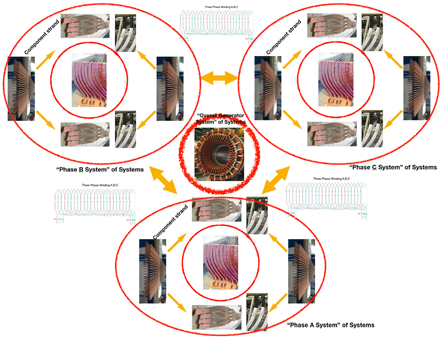
System of systems model for electrical generator.
Main contribution of this study are as follows
a. Study the machine with system perspective leading to find strand tilt issue
b. Effective flux mathematical calculation due to strand tilt
c. Nondestructive testing study to measure the strand tilt
2. Background
Minimizing non-conformance cost is one of the design criteria. The manufacturing process has never been entirely accurate. Manufacturing facilities always try to minimize any process related defect. Defects translate into losses, lesser efficiency, and non-conformances. In the paper, we present one of the processes related issue, which is associated with the performance of the generator. Generator winding is made up of several layers of copper strand transposed together in space. Manufacturing of such transposed winding is a complex process. When the generator windings are observed as a system of systems, the issue of strand tilt and deformed vent tubes were found. The paper address following two main questions; what is the resultant flux with such strand tilt? How this tilt can be measured, and the process can be corrected? What is the effect of the deformed vent tube in temperature distribution?
Failure studies done by Shipurkar et al. (2016), Ribrant and Bertling (2007), Spinato et al. (2009), Faulstich et al. (2011), and Echavarria et al. (2008) to understand, which components in the majority of the cases are responsible for the failure of the wind turbine. From 2005 to 2010, approximately 1200 wind turbine generators were studied and found that 70% of the failure caused by bearings. Windings failure is also one of the frequent cause of failure (Liu et al., 2018). Figure 2 presents two different efficiency wind turbines, with two different efficient generators. The power curve of the wind turbine will shift toward left utilizing more available wind, with a higher efficiency generator.
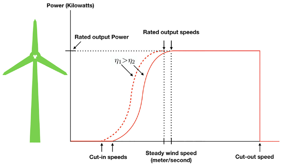
Wind turbine efficiency with two different efficiency generator systems.
Where
In the medium and high voltage generator winding (stator bar) encompasses strands and vent tubes. In this paper, these are considered as a basic interdependent and interacting component of the complex system. Voids present in the fully taped and VPI’ed stator bar lead to issues like partial discharge, corona discharge (Emery, 2005). These defects lead to losses and affect the efficiency of the whole complex system. Stator bars which might not perform well due to voids can be detected by partial discharge screening test (McDermid, 2014). Higher efficiency and lower losses are related to overall AEP (Annual Energy Production) and LCOE (Levelized Cost of Electricity) of the wind turbine system. The system of systems approach for the requirement for higher efficiency of the industrial system is presented by Pitis and Al-Chalabi (2005). In the electrical stator bar of the generator, internal partial discharge is 22% of the time responsible for insulation damage and is represented by Istad et al. (2011). Void in the insulation is one of the main contributing factors leading to partial discharge. Voids can be created during the curing phase (Barré and Napame, 2017). There are three defect locations that originate during the manufacturing process. Two at the borders of the main insulation and one located within the main insulation (Barré and Napame, 2017). These locations are presented in Figure 3. The remainder of the paper has been organized as follows. Section II describes the study of the misaligned component (strand) of the system and consequences. Section III presents the study of the deformed component (air vent tube) and what are the issues and challenge it brings to the overall system. Section IV presents a study on non-destructively detecting through computed tomography (CT), followed by a conclusion in section V.
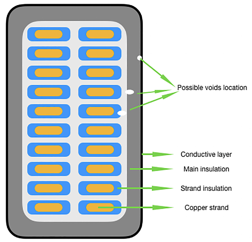
Three different void locations.
3. Misaligned component (strand) of the system
ISO/IEC/IEEE 5288 Annex G defines SoS, “system of systems (SoS) brings together a set of systems for a task that none of the systems can accomplish on its own. Each constituent system keeps its management, goals, and resources while coordinating within the SoS and adapting to meet SoS goals” (I. ISO, 2015). In this study, we are considering a single stator bar as one system. As per the above definition, this stator bar keeps its own goals, resources, and management system in terms of twisting the single strands to a certain degree in three dimensions. In order to meet the SoS goals, each single strand component coordinate with other strands in a certain way called rebelling. In the stator core, there are usually three phases, that is, Phase A, Phase B & Phase C, and each single-phase act as defined above, making the overall system of three separate systems having three phases. The benefit of strands oriented in a certain way is that the encountered losses are much lower. If any of the single system or sub-system is not contributing towards its goal, then it directly affects the performance of the overall system in terms of efficiency. On the other hand, if the system and sub-system contributing towards the overall goals, then it directly will be reflected in the AEP or generator efficiency. The benefit of this system approach is that it makes it possible to evaluate the performance of the overall system concerning components coordination. If the system is not performing as expected, then it gives the opportunity to check and correct the system orientation at the production level. If the system Efficiency is not as expected, then eddy current losses, or short circuit might be the leading cause. The full representation of the generator system is shown in Figure 1. Figure 3 presenting the dissection of ideal stator bar. For the demonstration purpose, the possible location of the voids has been shown. Strand tilt could lead to the possible void between main insulation and turn to turn insulation. Void free insulation is a challenging task, and Danikas and Sarathi (2014) presented the details of electrical machine insulation and related issues . New capacitances are created between the insulation layers due to the voids, which leads to lower breakdown voltage. A very high electrical field is generating due to induced voltage. This leads to partial discharge; Insulation leakage current increases due to avalanche current (Barré and Napame, 2017). Vogelsang et al. (2005) and Gulski and Kreuger (1992) studied the detection of partial discharge issues. The tilted strand can lead to the strand to strand short. As presented in Figure 4. Two shorted strand form one strand loop, and magnetic flux circulation will be affected. Induced current will lead to a higher winding temperature, affecting the lifetime of the insulation system. Yaghobi et al. (2014) study show turn to turn insulation fault detection through total harmonic distribution. The reason behind making several thin strands inside the stator bar is to reduce eddy losses. This is done by the linkage flux with the contours inside the conductors.
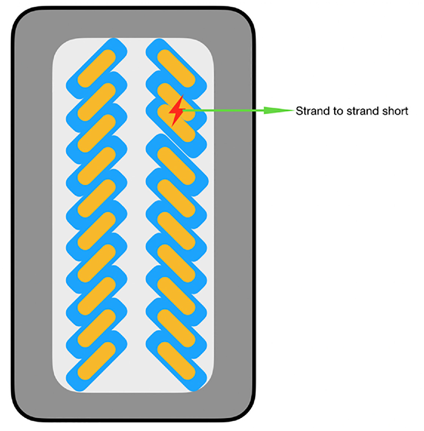
Turn-to-turn strand fault.
In order to make the current distribution, equal strands are transposed in a certain way. Figure 1 represents how the strands are stacked together and transposed along with the machine. This process is called roebelling, and the formed bar is called roebel stator bar (Robel, 1915). Eddy current losses and the effects can be minimized and canceled by forming a perfect stator bar, through the correct transposition of the strands. This can be achieved if every single strand for the equal axial length occupies every radial position. Maintaining the symmetry concerning constant axial and radial ends region flux various transposition methods like 540-degree transposition in the slot and 180-degree transposition, the end part can be used (Neidhofe, 1970). For compensating for end-region fluxes, voids (different from voids discussed previously, responsible for partial discharge) can be introduced (Bennington and Brenner, 1970).
3.1. Misaligned component (strand) of the system
If the strands are tilted at a

The voltage induced per inch of length of any tilted strand at position y will be

The voltage induced in strand length dx as compared with the hypothetical strand along the bottom of the stator bar side will be

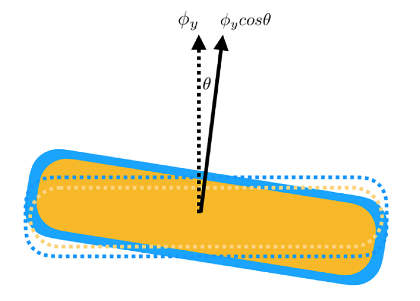
Resultant flux on every single tilted strand at location y.
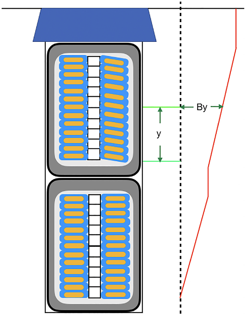
Slot induced eddy voltages with tilted strands.
A tilted strand selected beginning at position nY up from the bottom (where n is the starting elevation of the typical strand as fraction of stator bar height), as presented in Figure 7. After 540-degrees transposition, it will end-up at the position end of the core at (1-n)Y up from the bottom of the stator bar. Value of n expresses the initial vertical position of the typical strand relative to the stator bar height and can be any value between 0 and 1. To calculate overall voltage generated over the entire stator bar length in this strand relative to imaginary strand at the bottom of the stator bar, equation (3) need to be integrated for all the six part mentioned in Figure 7 (Ringland and Rosenberg, 1959).

Arrangement of strands in a stator stator bar with 540° core robelling.
Strand heights at various location are as follows:
first interval,

second interval, new origin for

third interval, new origin for

fourth interval, new origin for

Interval fifth and sixth are duplicating for first and second interval respectively. Putting the above values in equation (3)

After simplifying


Where:
Eddy voltage of all the strands relative to the hypothetical strand along the bottom of the stator bar side is equal as specified in equation (10).
4. Deformed component (air vent tube) of the system
High temperature is one of the limiting factors of machine design, and the generator is the primary source of insulation aging (Shipurkar et al., 2016). A possible cooling solution such as liquid (water or hydrogen) cooling has been developed to mitigate such issues (Gray et al., 2006; Jiang, 2010). There are some generators with an inner liquid-cooled stator bar, where the coolant flows inside of windings (Semken et al., 2012) in the vent tube. Winding temperature plays an essential role in the integrity of the winding insulation and strands, better cooling through vent tubes keeps the strands cooler around. Thermal degradation is the prime cause of issues related to insulation aging (Botha, 1997; Stone et al., 2004); proper cooling is necessary to support life. Windings temperature can also be higher due to harmonic losses due to converter (Yin, 1997), issues on the insulation system when with converter are addressed by Bauer et al. (2002) and Wheeler (2005). Usually, to assure thermal integrity of the insulation system, various qualification measure like thermal cycling test need to be performed (Istad et al., 2011) but is not the scope of this paper. One of the components, that is, responsible for the safe operation of the system of stator bar, is the air vent tube. Air vent tubes are usually used in high voltage stator bars. Air vent tubes are meant to flow the coolant in between the stator bar, to overcome the issue of the heated strand. Strands get heated due to high current flow. Ideally, the vent should look like, as presented in Figure 6. Manufacturing defect and use of soft metal for vent tube, during stator bar formation leads to vent tubes deformation. Once the formed stator bar goes to the process of vacuum pressure impregnation, resin occupies the available area. The stator bar then passes through an oven for heating, and resin turns into hard. Figure 8 represents an example of a deformed vent tube. The area affected by the deformed vent tube has been circled with red. Although deformation of vent tube known for the manufacturing industry but presented here in relation with strand tilt study. The area around the vent tube can be affected due to non-uniform cooling. This might affect the winding insulation and, eventually, the performance of the system. Case 1 in Figure 9 presents an ideal coolant flow situation, where nearby strands encounter almost the same average temperature. Coolant can be air, water, or some other types. In Case 2 vent tube is deformed during the manufacturing process.
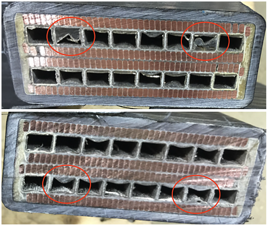
Disectional view of deformed vent tube.
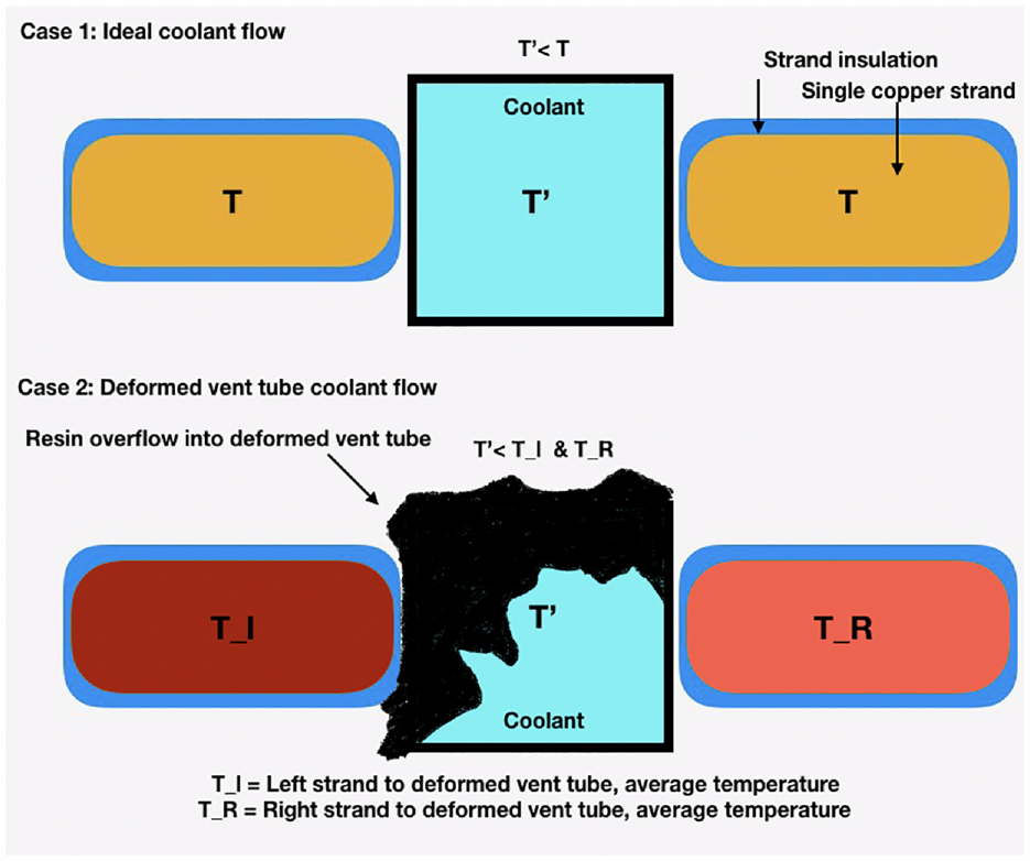
Deformed vent tube effect on nearby copper strand temperature.
The open area provides a path to the resin to fill in and get solid after oven processing. This deformation leads the different temperatures that is, Tl & TR, and also higher in magnitude as compared with the ideal case. For the better performance of the overall system, issues associated with overheating should be avoided. One such study to reduce overheating is presented by Singh et al. (2018, 2020), where to overcome the overheating challenges the heat exchanger in the air-to-air cooled generator system is replaced with open-air cooled system. Achieved results presented the advantage of an average of 40°C in winding and 30°C in bearing temperature. Studies performed by Singh et al. (2019a, 2019b, 2019c, 2019d) also addresses the issues related with manufacturing, windings & bearings with a similar generator and with similar qualification process. Vent tube deformation can be fixed by knowing the location and adjusting the manufacturing process accordingly. This will require to either dissect the stator bar to measure defect or to non-destructively measure the deformation. Dissecting stator bar might not be a preferred choice due to an expensive process. This and the previous section discussed the components indirectly responsible for the performance of the overall generator system. Components (strands and air vent tube) interaction and interdependence have been discussed, and effects have been presented. Both of the cases require a non-destructive testing technique to overcome these issues. This is addressed in the next section with the help of a case study.
5. Non-destructively misaligned and deformed component detection – A case study
In the previous sections the cause of strand tilt and affected flux is presented, also the possible impact on overall system has been discussed. The perfect aligned strand manufacturing is nearly impossible due to human error and machine precision involved. Manufacturing adjust the process as close as it can to make a perfect coil. To measure the perfectness of the coil only proven method is destructively dissect the coils time to time. Improperly aligned strands lead to eddy current losses and voids. Voids cause partial discharge and corona issues in the stator bar. The manufacturing stator bar is a complex process. To check whether the strands are tilted or manufactured correctly, destructive testing is commercially not a good idea. Figure 10 represents the destructive testing method to measure strand tilt in the stator bar of the electrical generator.
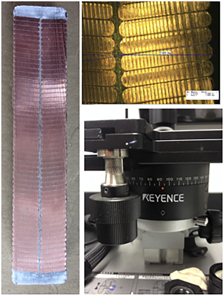
Destructive testing method to measure strand tilt in generator electrical stator bar.
In order to visualize strand tilt at various locations, multiple measurements are required. During the study of predicting the strand tilt and vent deformation without dissecting stator bar, various non-destructive testing technologies like X-ray, ultrasonic sensors were tried unsuccessfully. One point to note is that resin-rich stator coils are not suitable to ship in uncontrollable temperature situations. In this study, we followed a unique approach of evaluating strand tilt with a healthcare CT scan. Figure 11 represents the stator bar CT scan samples process. Figures 12 and 13 represents CT scan images with noise and scattering where trigonometric measurement of the tilt is still possible and not very clear. Figure 14 present the results using the feature of maximum intensity projection. Using this technique in the scanning improved the quality of image. Figure 15 presents three sectional views of the sample with using the feature of maximum intensity projection. The Upper left is the top view and is very useful to analyze the strand crossover gap area after the initial press of the manufacturing process. The top-right view represents the Y-direction, where side overlap of the strands can be evaluated. This is useful to evaluate the strand to strand gap (if any). The bottom view is the X-direction view. This is the view where strand tilt at any particular location can be measured, without dissecting the stator bar. Once identified, the required mitigation measure can be implemented during manufacturing to avoid strand tilt.
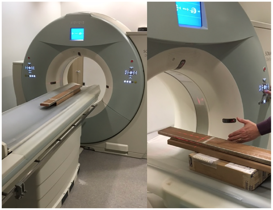
CT scanning of a consolidated stator bar performed on a CT scanner.

Scattered CT scan image of a consolidated stator bar sample.

CT scan of stator bar sample with average intensity projection.
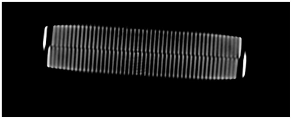
CT scan of stator bar sample with maximum intensity projection.

Three sectional view of stator bar sample CT scan with maximum intensity projection.
Computed tomography (CT) and X-ray both are based on X-rays. The difference is CT use combination of may X-ray measurement taken together and different angle. In this way a sectional view can be generated. These sectional views are also called virtual slices. Usually CT scan is meant to scan body, the industrial CT scanner are meant to scan metal and insulated machine parts. Several different CT scanners used for the strand tilt measurement in this study. Intensity projection plays an important role in the CT scanning process. There are mainly three type that is, average, maximum and minimum intensity projects.
Using the feature of maximum intensity projection in the CT, the results were comparatively good, and the tilt can be measured effectively. From the achieved results the angle of tilt can be measured with simple trigonometric calculation.
6. Conclusion
Paper presented a unique system perspective to visualize the electrical generator system. Two system components that is, stator bar strands and air vent tube, have been discussed for their interaction and interdependence toward a complex system of stator bar. Strand tilt during the manufacturing process of the generator stator bar is characteristic, but less discussed in the past. Result obtained were excellent and can be useful for various application during stator bar manufacturing. Doughnut shape CT scanner also useful to slide in the stator bar. This effort eventually contributes towards the performance of a more complex system of three-phase winding. Losses in three-phase winding determine the performance and efficiency of the final overall complex system of an electrical generator. This system approach suggests the ways to maintain or increase overall system efficiency if a few components are not aligned or cannot be aligned. The study presents the effective flux calculation due to strand tilt, and a nondestructive testing technique to measure the strand tilt. Paper presented the study of electrical machines from a system perspective and might open the door to extend beyond electrical machines like a gas turbine, steam turbine, transformers.
Footnotes
Declaration of conflicting interests
The author(s) declared no potential conflicts of interest with respect to the research, authorship, and/or publication of this article.
Funding
The author(s) received no financial support for the research, authorship, and/or publication of this article.
