
Abstract
Experimental investigations of wind turbine blades having NACA airfoils 0021 and 4412 with and without tubercles on the leading edge have been performed in a wind tunnel. It was found that the lift coefficient of the airfoil 0021 with tubercles was higher at Re = 1.2×10⁵ and 1.69×10⁵ in post critical region (at higher angle of attach) than airfoils without tubercles but this difference relatively diminished at higher Reynolds numbers and beyond indicating that there is no effect on the lift coefficients of airfoils with tubercles at higher Reynolds numbers whereas drag coefficient remains unchanged. It is noted that at Re = 1.69×10⁵, the lift coefficient of airfoil without tubercles drops from 0.96 to 0.42 as the angle of attack increases from 15° to 20° which is about 56% and the corresponding values of lift coefficient for airfoil with tubercles are 0.86 and 0.7 at respective angles with18% drop.
Introduction
In the last decades extensive research has been carried out to improve the efficiency of large wind turbines. However, improvement by altering and modifying the shape of the wind turbine blades has been exhausted. The modern wind turbines must not only run at higher efficiencies but also provide smooth and consistent output while transiting between various winds velocities. In this regard a special flow control method‚ namely the tubercle structures was discovered and is being investigated extensively. Tubercle is a morphological feature found on the flipper of Humpback whales and is found to influence the maneuverability of the whales in a dramatic way. These are rounded, leading edge structures that alter the flow field around the airfoil shown in Figure 1.
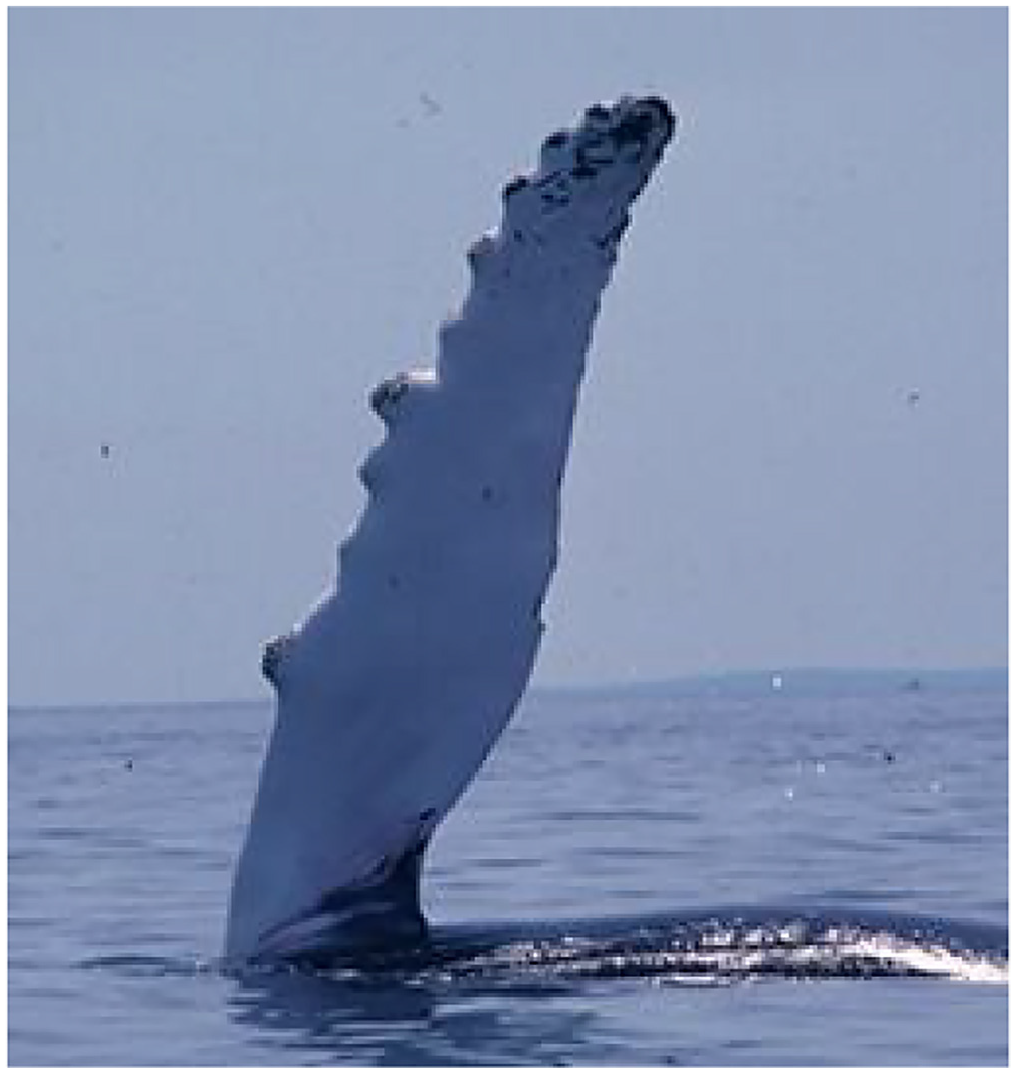
Humpback whale calf with tubercles visible on flipper leading edge.
It has been observed that these structures act as effective flow control features assisting in lift enhancement and drag reduction. Lift enhancement is achieved by maintaining flow attachment at relatively large angles of attack thus delaying stall and increasing the maximum lift coefficient without penalizing drag (Fish and Battle, 1995). A major advantage of delayed stall is that higher lift coefficient could be achieved at lower flow velocity for an airfoil with tubercle structures when compared to an unmodified airfoil. Due to lower drag associated, improved efficiency could be achieved resulting in smooth power curves for wind turbines during transition from lower to higher wind velocities. Several devices with tubercles are available commercially such as surf boards and ceiling fans which could be incorporated into the leading edge either by fixing these structures or milling these protrusions into the airfoils edges.
State of the art concept
Tubercles are found to be very effective in increasing the maneuverability of the Whale to catch its prey. More specifically it can make very sharp turns and swim at very high angles of attack resulting in delay in flow separation above the surface and delayed stall is achieved. During the last decades, inspired by the nature, several investigations have been performed on airfoils with tubercles to simulate and investigate their effects on the lift and drag parameters. Miklosovic et al. (2004) performed experiments on NACA 0020 profile at Reynolds numbers in the range of 505,000–520,000. It was shown that by incorporation of the tubercles on airfoils, flow separation was delayed resulting in an increase in the maximum lift coefficient and the angle at which stall begins. A 40% increase in the stall angle and a significant decrease in the total drag in post-stall regime compared was revealed to an unmodified surface. Johari et al. (2007) demonstrated that tubercles actually deteriorate the performance of airfoils at lower angles of attack in the pre-stall region. Rise in maximum lift up to 4.8%, decrease in drag reduction up to 10.9% and 17.6% increase in the lift to drag ratio was reported by Watts and Fish (2005) by incorporating Tubercles along the leading edge of the NACA 63-021 airfoil. The authors varied the amplitude and spacing of sinusoidal tubercles and found that larger amplitude tubercles promote softer stall characteristics. These studies were carried out on a model humpback whale’s flippers which implied that these studies were only successful when applied to this particular geometry. However these experiments were carried out in a Reynolds number range of 500,000–631,000.
Van Nierop et al. (2008) performed wind tunnel experiments and noted that bumps on the leading edge of model humpback whale flippers caused them to stall more slowly at a higher angle of attack. Moreover it was found that with the increase of the amplitude of the bumps, the lift curve leveled out, and stall delay was not affected by the wavelength of the bumps. Miklosovic et al. (2007) studied the scalloped leading edges and found that the scallops had largely a 3-D advantage depending on the planform shape and the Reynolds number. At pre-stall angles of attack, the decrease in lift and moment whilst increase in drag was observed but the 3-D effects were much smaller in magnitude. The poststall behavior was dissimilar: increasing lift/moment and decreasing drag. The generation of vortices by the scallops was beneficial only to 3-D planforms in the range of Reynolds numbers tested. The authors anticipated that airfoils with tubercles might have usefulness on lifting surfaces that are required to operate past their stall point, such as wind turbine blades at low speeds and unsteady winds.
Flow visualizations were carried out by Custodio (2007) on the airfoils with tubercles. It was noted that pairs of counter rotating stream-wise vortices were generated in the troughs between tubercles. The flow was separated behind the trough in the post-stall region. Moreover increased boundary layer momentum exchange, non-uniform separation characteristics and vortices lift were thought to be contributing in performance enhancement of the airfoils with tubercles. Hansen (2000, 2012) validated the performance enhancement in the post-stall region for Reynolds number of 120,000 for NACA airfoils 0021 and 65-021 along with stream-wise vortices. Optimization of the tubercles was also carried out in the same study. It was found that the tubercles with smaller amplitude and spacing were more effective. The performance of the tubercles was also affected by the airfoil profile and remained unchanged when the boundary layer became turbulent. Leung (2014) performed a rough outdoor testing of the multiple wind turbine blades with tubercles and reported 16%–30% increase in the power output. Research on the Tubercle Leading Edge (TLE) concept has helped to clarify the aerodynamic issues such as flow separation, tonal noise, and dynamic stall (Aftab et al., 2016). Experimental study considering spherical TLE is carried out at Reynolds number of 200,000. The experimental results showed that spherical TLE improved performance compared to airfoil without tubercles (Abate and Mavris, 2018; Aftab and Ahmad, 2017). It was noted that tubercles could generate a unique flow control mechanism, offering the humpback exceptional maneuverability. Experimental and numerical studies have shown that the flow pattern over the tubercle wings is quite different from conventional wings.
Hensen et al. (2011) investigated experimentally the effect of sinusoidal leading-edge protrusions on the performance of two NACA airfoils. Force measurements on full-span airfoils indicated that different combinations of tubercle amplitude and wavelength were more effective when compared to the unmodified airfoils. It was found that reducing the tubercle amplitude leads to a higher maximum lift coefficient and larger stall angle. In the post-stall regime, however, the performance with larger amplitude tubercles was more beneficial. Reducing the wavelength of tubercles leads to improvements in lift performance, including maximum lift coefficient, stall angle, and post-stall characteristics. However, there is a certain point at which further reduction in wavelength has a negative impact on the performance. The results also showed that tubercles act in a manner similar to the conventional vortex generators. Rostamzadeh et al. (2014) performed experimental and numerical tests to investigate the effect of tubercles on the flow structure over full-span modified wings based on the NACA 0021 profile, in the transitional flow regime. It was noted that a skew-induced mechanism caused the formation of streamwise vortices and flow separation in the delta-shaped regions near the trailing edge. From the results it was demonstrated that the presence of vortices was not favorable to the performance of full-span wings pre-stall but was beneficial to the post-stall that produced an enhanced momentum transfer effect reducing flow separation and increasing the generated amount of lift.
Karthikeyan et al. (2014) investigated experimentally the effect of tubercles at the leading edge of a NACA 4415 airfoil at a low Reynolds number of 120,000 and at angles of attack of 6°, 12°, and 18°. The aerodynamic performance of the NACA 4415 airfoil with leading-edge tubercles was compared against an airfoil without tubercles (baseline) through pressure measurements. At the lower angle of attack (α = 6°), the extent of the laminar separation bubble was the dominant flow feature over the baseline airfoil, whereas it was pointedly changed by the presence of tubercles at the leading edge. The adding of tubercles caused the formation of pockets of smaller separation bubbles instead of one single long bubble spreading along the baseline airfoil. The modified airfoil maintained attached flow until 50% of the chord, instead of complete separation starting from the leading edge, as was noticed for the baseline case. The size of the recirculating zone downstream of the separation was also significantly reduced by the tubercles. All these factors contribute to the increased performance of the airfoil with leading-edge tubercles, especially at poststall angles of attack.
Post et al. (2018) tested six different wing geometries, smooth and sinusoidal leading-edge models, swept and unswept configurations, at angles of attack of −2° to 24° and at Reynolds numbers in the range of 100,000–500,000. It was found that sinusoidal leading-edge wings observed loss of lift caused by stall and generated a gradual decrease in the lift whilst 25% higher lift in the poststall regime. Kim et al. (2018) investigated two wing models with and without tubercles at the Reynolds number of 180,000 based on the free-stream velocity and mean chord length. At this Reynolds number, tubercles delay the stall angle by 7° and 22% increase the maximum lift coefficient. At a low angle of attack, flow separation first occurred near the tip region then progressed inboard toward the wing root for the model without tubercles with increasing angle of attack, whereas tubercles produced two types of vortical motions and block the inboard progression of flow separation, resulting in delayed stall from α = 8° to 15°.
Wei et al. (2018) investigated aerodynamic characteristics and surface flow patterns for two wings; one baseline wing and other wing modified with leading-edge tubercles. It was shown that the two airfoil profile orientations and alignment of tubercles relative to the leading edge did not lead to the substantial changes to the major surface flow features. However, aligning the tubercles normal to the leading edge showed noticeable improvement in the L/D ratio for angle of attack in the range of 2°–7°, when compared with its baseline counterpart wing. Stall behavior was improved slightly for both modified wings with different tubercle orientations as compared with their baseline counterparts, whereas both lift enhancement and drag reduction could be achieved at higher angles of attack, α = 20°. Hansen et al. (2016) studied the sinusoidal modifications to the leading edge of a foil, or tubercles and examined the formation of streamwise vortices at a low Reynolds number of Re = 2230. It was found that the circulation of vortices increased in the downstream direction and the presence of strong pressure gradients near the leading edge gives rise to the generation of a pair of streamwise vortices between the tubercle peaks. A horseshoe-shaped separation zone was shown to initiate behind a tubercle trough. Flow visualization and particle image velocimetry studies supported these observations and demonstrated that the flow characteristics varied with time, particularly near the trailing edge and at a higher angle of attack. It was shown that the performance of a foil with tubercles is slightly better than that of an unmodified foil.
Bolzon et al. (2016) studied two swept NACA 0021 wings at angles of attack of 0°, 3°, 6°, 9°, and 12°. One wing had a smooth leading edge and the other had a tubercle leading edge. Sweeping the tubercle wing resulted in stronger vortices. From 6° onwards tubercles reduced the strength of the wingtip vortex. The tubercle troughs tended to produce local maxima and minima in the profile and induced drag coefficients, respectively.
Since the topic has been discussed controversially in literature, the main objective of present study is to perform further investigations on tubercles to investigate their behavior and confirm their usefulness contribution from the wingtip region. Hence due to controversial discussion on the influence of tubercles in literature, further investigations were performed on the subject. Experimental investigations on tubercles were carried out in a wind tunnel and the details are presented in the following sections.
Experimental setup
The experiments were conducted using the large subsonic wind tunnel at the Department of Ocean Engineering, the University of Rostock, Germany. The wind tunnel features a closed circuit with an open test section of length 2.80 m and a square nozzle with dimensions of 1.40×1.40 m. The air velocity achievable in the tunnel ranges from 5 to 60 m/second, generated by a 200 kW axial fan and investigations identified an average turbulence intensity of 0.5%. The turbulence intensity (%) along the Z and Y-axis at velocities of 10, 20, and 30 m/second in the subsonic wind tunnel at the position of the model tests is shown in Figure 2.
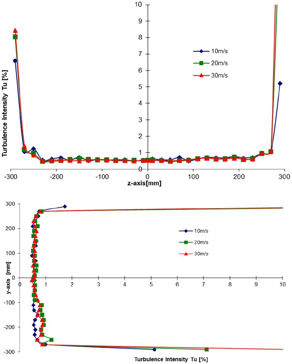
Turbulence intensity (%) along the Z and Y-axis at velocities of 10, 20, and 30 m/second in the subsonic wind tunnel at the position of the model tests.
Instrumentation and testing
The test section features a six-component force balance used to measure drag and lift parameters. The balance is composed of six strain gauge-based force transducers (Hottinger Baldwin Messtechnik (HBM) GmbH). Along the X-direction, it can register drag up to 50 N at an accuracy of 0.02%, whereas in the Y-direction, lift is registered up to the maximum force of 100 N, again at an accuracy of 0.02%. The values are recorded at a sampling frequency of 1200 Hz for 20 seconds each. Also, the flow velocity and other environmental data like temperature, atmospheric pressure, and humidity are constantly recorded. The balance is connected to a turn table allowing a free 360° rotation of any model. Pressure measurements were performed using piezo electric differential sensors by Honeywell each having a measurement range of ±3000 Pa and an accuracy of 0.25%. The Measurements were performed at a rate of 500 Hz for 20 seconds each.
Investigated configurations
Two different NACA profiles, 0021 and 4412 were investigated. 3D models of airfoils were designed in Solidworks and printed using a 3D printer. Flat airfoils were used as the as the basic reference. The dimensions of all the investigated profiles are identical, that is, chord length of 120 mm and span of 580 mm. Splitter plats are placed on both sides of the airfoil during measurements in the wind tunnel to avoid creation of vortices which would disturb main flow over the airfoils. Geometry of the tubercles applied is sinusoidal having a wavelength of 13 mm and an amplitude of 4 mm. The dimensions are selected based on the results of experiments performed by Hansen (2000, 2012). The airfoil configurations used for testing with and without tubercles are shown in Figure 3 and airfoil in the Test section of the Wind tunnel is illustrated in Figure 4.
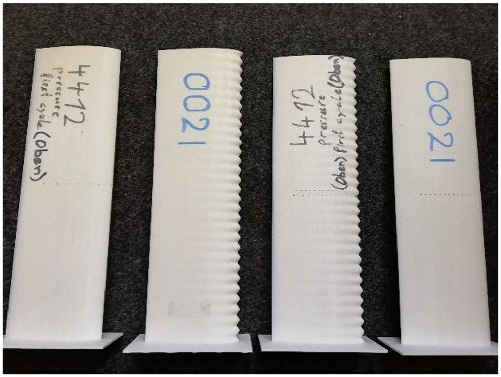
Airfoil configurations used for testing with and without tubercles.
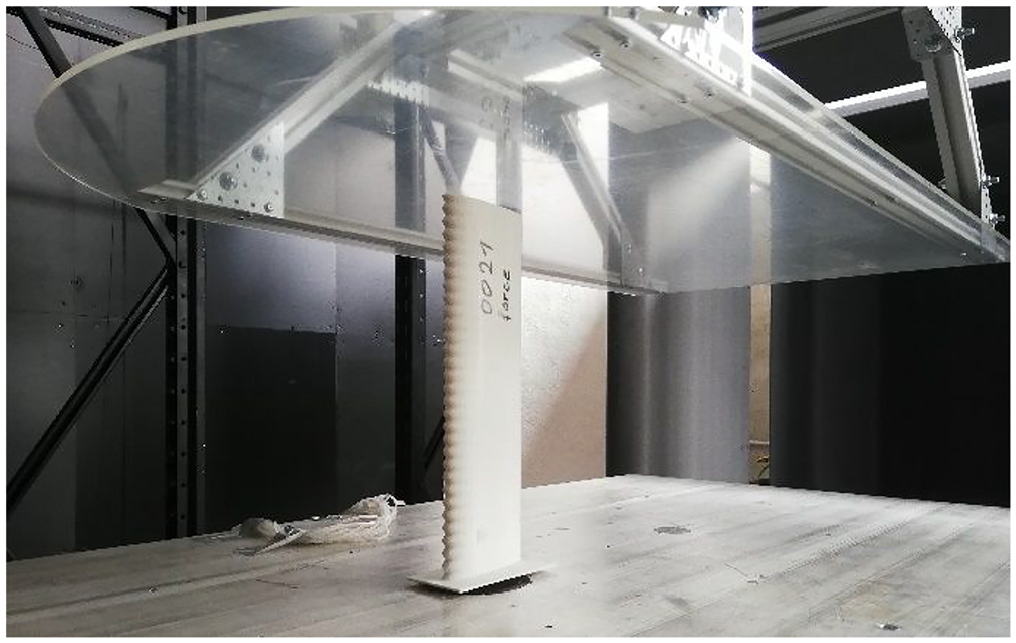
Airfoil in test section of the wind tunnel.
Pressure holes are drilled in the profiles at a distance of 5 mm with each other along the chord length. Since the area near the leading edge is of more importance regarding vortices generation and flow separation, a total of fifteen holes are drilled which cover almost 75% of the chord length whilst the diameter of each pressure hole is 1 mm. The holes for surface pressure distribution along the trough and crest of chord length are shown in Figure 5.
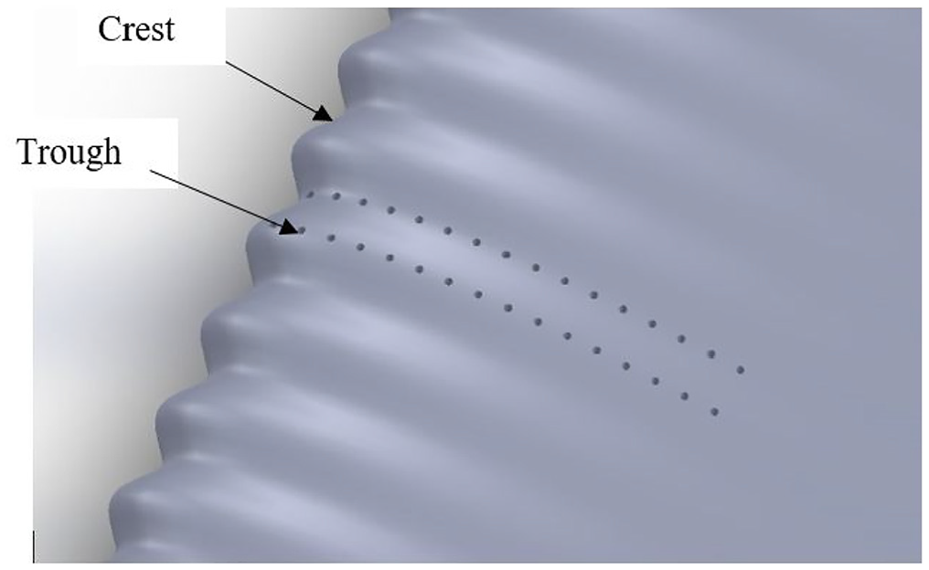
Holes for surface pressure distribution along the trough and crest of chord length.
Results and discussion
Experimental results of the NACA airfoil 0021 and 4412 with and without Tubercles on the leading edge were obtained in the wind tunnel. The results included measurement of the Lift and Drag coefficients of both airfoil configurations.
Lift and drag coefficients
The variation in the lift and drag coefficients of flat and modified Tubercle airfoils at various Reynolds numbers and angles of attack are presented in the following subsections.
Lift and drag coefficients for NACA 0021
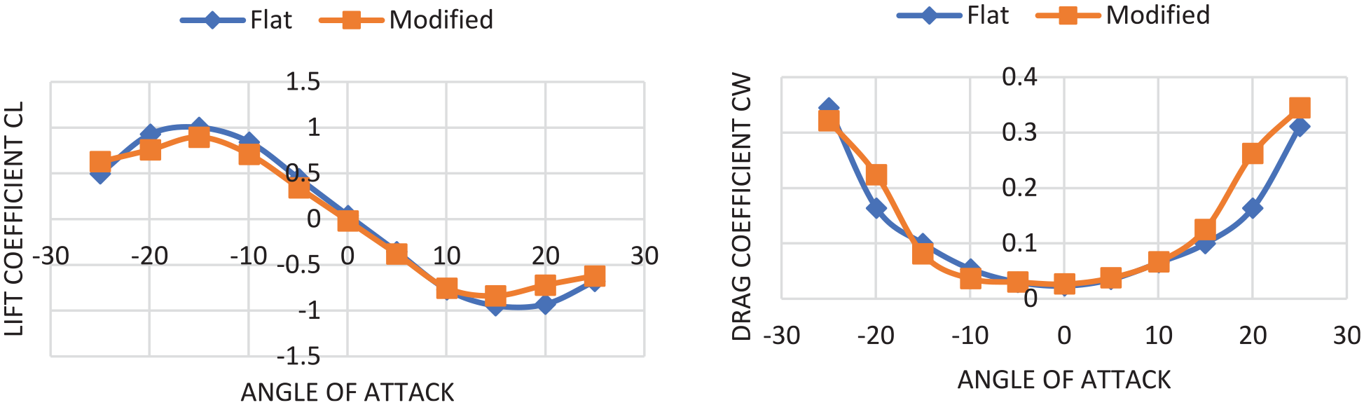
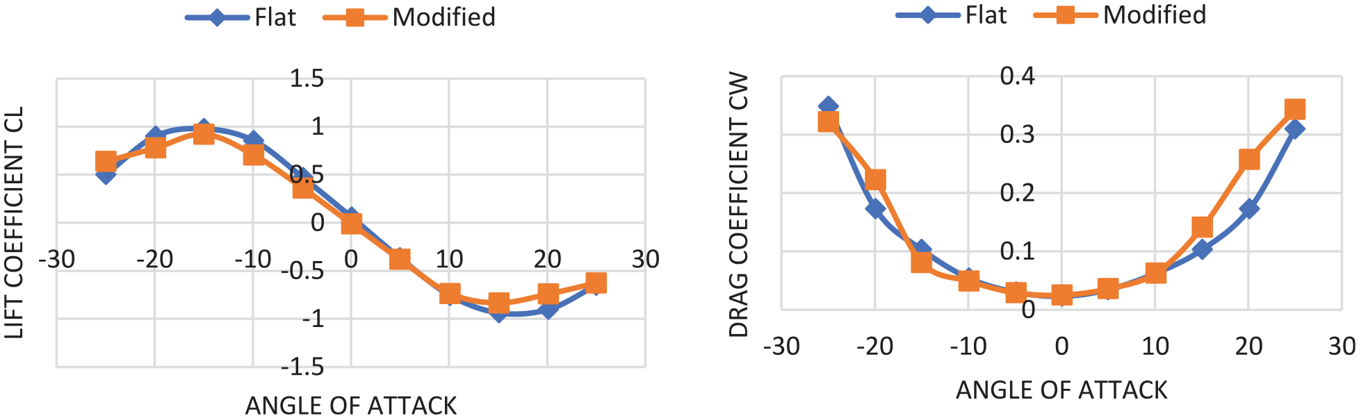
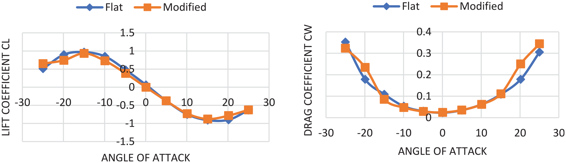
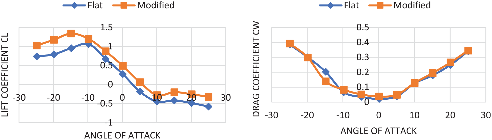
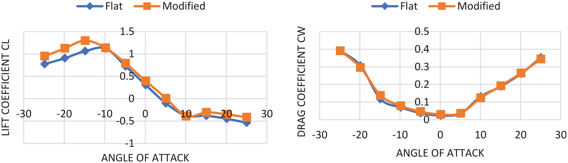
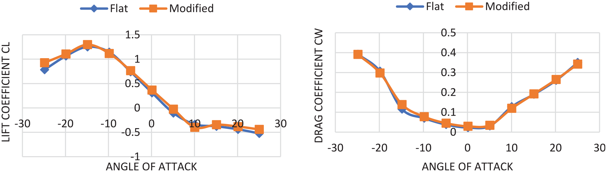
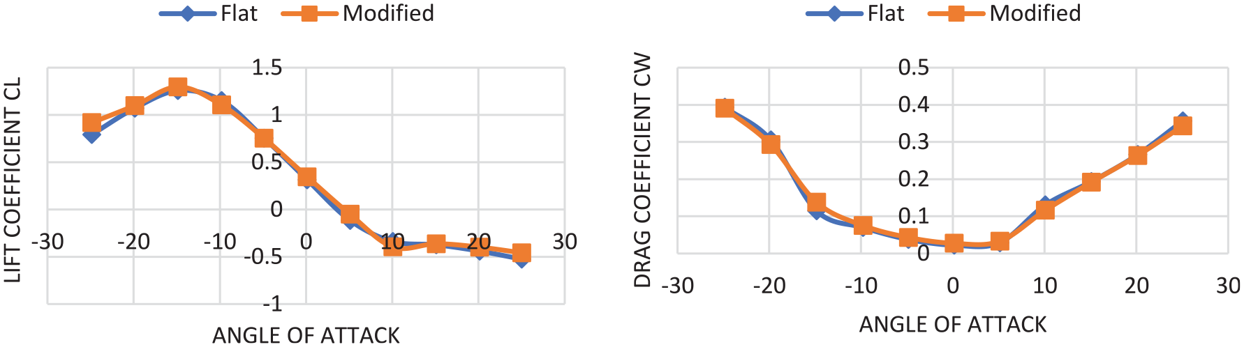
The variation in the lift coefficients (left) and drag coefficients (right) versus different angles of attack (in degrees) in the range of −30° to 30° and at different Reynolds numbers in the range of 8.44×10⁴ to 3.37×10⁵ of flat and modified tubercle airfoils are illustrated in Figures 6 to 12.
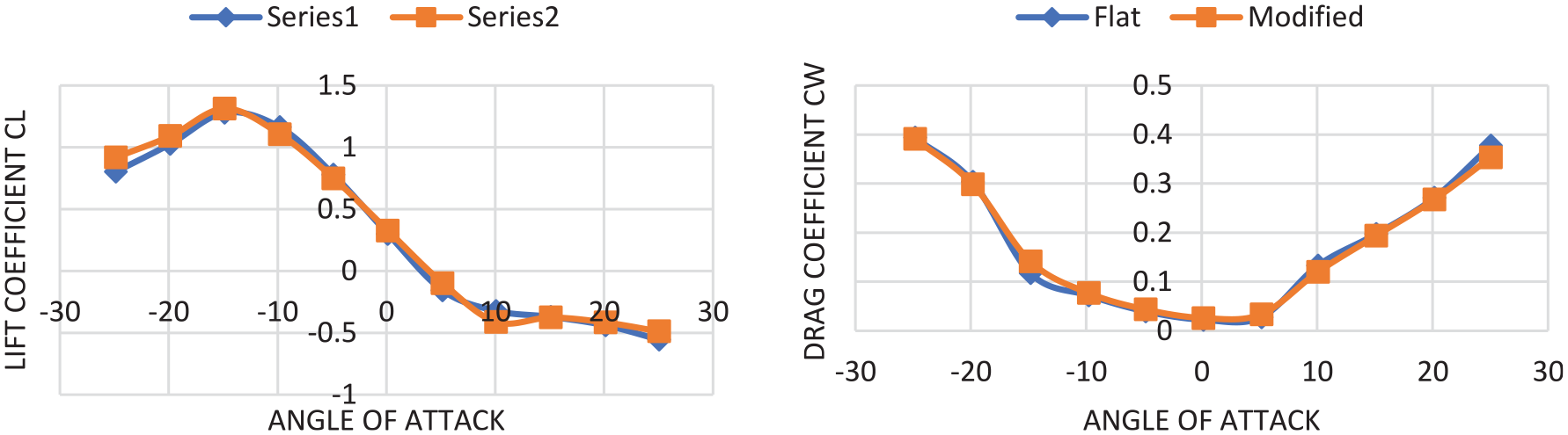
Lift and drag coefficients versus angle of attack for NACA 0021 at Re = 8.44 × 10⁴.
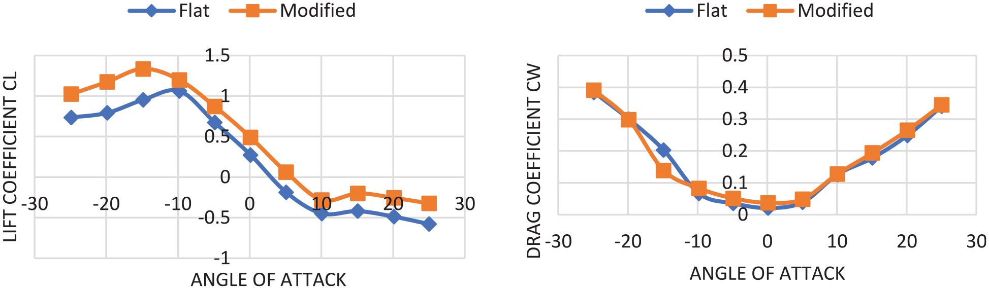
Lift and drag coefficients versus angle of attack for NACA 0021 at Re = 1.2 × 10⁵.
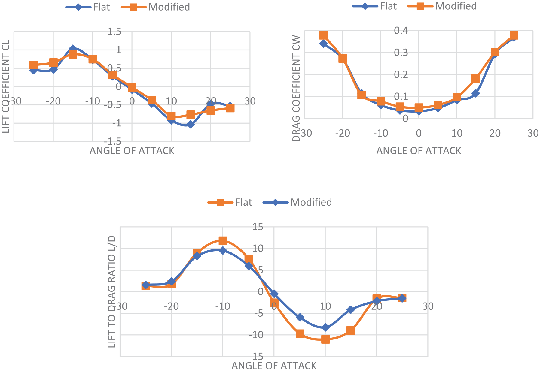
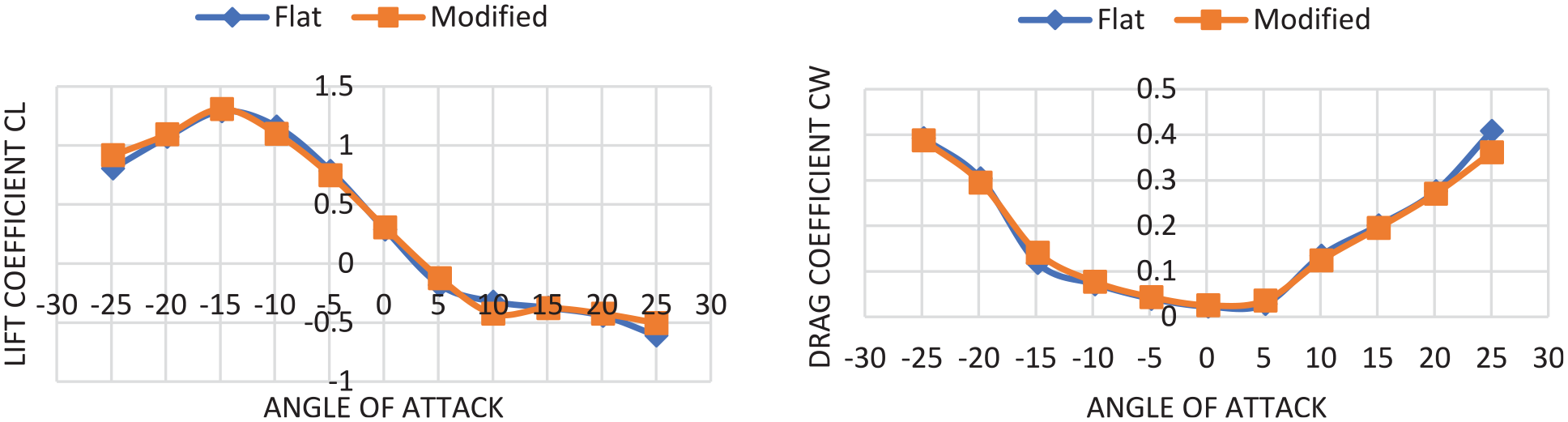
Lift and drag coefficients versus angle of attack for NACA 0021 at Re = 1.69 × 10⁵.
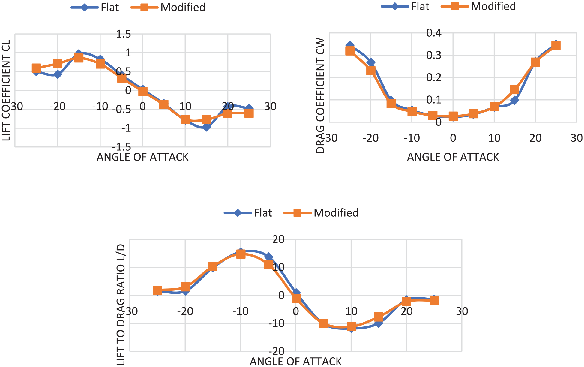
Lift and drag coefficients versus angle of attack for NACA 0021 at Re = 2.11 × 10⁵.
Lift and drag coefficients versus angle of attack for NACA 0021 at Re = 2.53 × 10⁵.
Lift and drag coefficients versus angle of attack for NACA 0021 at Re = 2.95 × 10⁵.
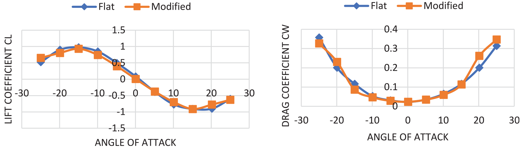
Lift and drag coefficients versus angle of attack for NACA 0021 at Re = 3.37 × 10⁵.
From the Figures 6 to 12 it was observed that the Lift and Drag curves for NACA 0021 resemble qualitatively and quantitatively the ones reported in the relevant literature (Aftab and Ahmad, 2017). The lift coefficients first increase with increasing angle of attack and then decreases after angle of attack of 15°. The behavior observed is identical for both positive and negative angle of attacks due to its symmetrical shape. The maximum value of lift coefficient is found to be near the angle of attack of 15°. The drag coefficient however keeps increasing with increasing angle of attack. In contrast to many claims in the literature, the Tubercles seems to have limited influence on the aerodynamics properties of tubercle airfoils. The lift coefficient curve of airfoil with tubercles remains relatively unchanged for a wide range of angles of attacks in the post critical regime at lower Reynolds numbers. At Re = 1.69×10⁵, the lift coefficient of flat airfoil drops from 0.96 to 0.42 as the angle of attack increases from 15° to 20° which is about 56%. The corresponding values of lift coefficient for airfoil with tubercles are 0.86 and 0.7 at respective angles with 18% drop. Although the peak value of lift coefficient for Tubercles is a bit lower that the flat one whereas these remained unchanged for a larger range of angles of attack. The measured values of lift coefficient at higher Reynolds numbers that is, Re = 2.11×10⁵ and 2.53×10⁵ are lower and the drag coefficient is higher for airfoil with tubercles.
Lift and drag coefficients for NACA 4412
The variation in the lift coefficients (left) and drag coefficients (right) versus different angles of attack in the range of −30 to 30 and at Reynolds numbers in the range of 8.44×10⁴ to 3.37×10⁵ of flat and modified tubercle airfoils are illustrated in Figures 13 to 19.
Lift and drag coefficients versus angle of attack for NACA 4412 at Re = 8.44 × 10⁴.
Lift and drag coefficients versus angle of attack for NACA 4412 at Re = 1.2 × 10⁵.
Lift and drag coefficients versus angle of attack for NACA 4412 at Re = 1.69 × 10⁵.
Lift and drag coefficients versus angle of attack for NACA 4412 at Re = 2.11 × 10⁵.

Lift and drag coefficients versus angle of attack for NACA 4412 at Re = 2.53 × 10⁵.
Lift and drag coefficients versus angle of attack for NACA 4412 at Re = 2.95 × 10⁵.
Lift and drag coefficients versus angle of attack for NACA 4412 at Re = 3.37 × 10⁵.
From the Figures 13 to 19 it can be seen that behavior of NACA 4412 under similar flow conditions is different from the NACA 0012. Due to its non-symmetrical shape of the results profile, only the results of negative angles of attack are of importance. No significant change neither positive nor negative can be observed at any Reynolds number or angle of attack. The deviation in curves in Figure 13 are a little bit higher because the measured forces are too small due to very low wind velocity and uncertainties are much higher. The reason behind this limited or negative influence of leading-edge with tubercles of NACA 4412 may be due to its geometry. More optimized geometries with a different wavelength and amplitude may influence the aerodynamics properties of the airfoil in a completely different way.
Conclusions
Based on the experimental investigations and results obtained it can be stated that NACA airfoil 0021 with tubercles influence the aerodynamic properties of the airfoil in a positive way at higher angles of attack and low Reynolds numbers especially at 1.69×10⁵. The lift coefficient of flat NACA airfoil 0021 falls abruptly in post critical region whereas the airfoil with tubercles on the leading edge smoothen the curve and the lift coefficient profile remains comparatively unchanged for a wide range of angles of attack. This phenomenon must have been caused by the partial flow separation and reattachment that is, partial flow separation at angles of attack between 10° and 15° and flow re-attachment near the leading edge at an angle of attack of 20°. As the Reynolds number increases the lift coefficient of tubercles airfoil decreases for all angles of attack compared to the airfoil with flat leading edge. The drag coefficient also increased especially at higher angles of attack. However, no such deviation was observed for the NACA airfoil 4412.
Footnotes
Declaration of conflicting interests
The author(s) declared no potential conflicts of interest with respect to the research, authorship, and/or publication of this article.
Funding
The author(s) received no financial support for the research, authorship, and/or publication of this article.