



Abstract
The quest for reduced levelized cost of energy has driven significant growth in wind turbine size; however, larger rotors face significant technical and logistical challenges. The largest published rotor design is 25 MW, and here we consider an even larger 50 MW design with blade length over 250 m. This paper shows that a 50 MW design is indeed possible from a detailed engineering perspective and presents a series of aero-structural blade designs, and critical assessment of technology pathways and challenges for extreme-scale rotors. The 50 MW rotor design begins with Monte Carlo simulations focused on optimizing carbon spar cap and root design. A baseline design resulted in a 250-m blade with mass of 502 tonnes. Subsequently, an aero-structural design and optimization were performed to reduce the blade mass/cost with more than 25% mass reduction and 30% cost reduction by determining optimal blade chord and airfoil thickness for best aero-structural performance.
Keywords
Introduction
Wind energy is playing an essential role in producing clean energy and growing rapidly in recent years (Ju et al., 2020), and the U.S. White House is targeting big expansion for offshore wind energy in 2021 (The White House, 2021). With the increasing demands of clean and renewable energy resources, a major goal has been established by the Department of Energy (DOE) that wind energy provides 20% of U.S. electricity by 2030 (USDOE, 2008), this goal has been extended to 35% wind penetration in 2050 (Vision, 2015); in 2021, the U.S. White House has established a target to deploy 30 GW of offshore wind by 2030 (The White House, 2021). To achieve these goals, more wind capture is needed and it is expected that this can be achieved with turbines that are offshore and of larger size (Cox and Echtermeyer, 2012).
Wind turbine size keeps growing to capture more energy while decreasing energy cost. In 1980s, the typical wind turbines only had a rotor radius of approximately 8 m (Wiser et al., 2016). In 2014, MHI Vestas developed an 8 MW wind turbine, V164-8.0 MW, with a rotor radius of 82 m; 2 years later, they upgraded its power capacity to 9.5 MW with the same rotor size. In 2016, LM Wind Power built a wind turbine blade with a length of 88.4 m (LM, 2016) for the Adwen (2017) 8 MW offshore wind turbine platform with a rotor radius of 90 m. In 2019, LM Wind Power built a 107-m blade for General Electric (GE, 2019, 2020) Haliade-X 12 MW wind turbine (uprated to 13 MW in 2020), which can power up to 16,000 average European homes, with a rotor radius of 110 m and 260-m tower height. Siemens-Gamesa has launched a new offshore direct drive wind turbine at 14 MW, with a rotor radius of 111 m, the prototype is expected to be ready in 2021 (SIEMENS, 2020).
The research community has been active as well in designing extreme-scale (10 MW or more) wind turbines, as various reference model definitions of blade design and different optimization techniques for large-size wind turbine blades have been investigated. The DTU 10-MW reference wind turbine has been released and served as a reference turbine for the European InnWind project (Bayati et al., 2016). Since 2010, Griffith (2013a, 2013b), Griffith and Ashwill (2011), and Griffith and Richards (2014) designed a series of 100-m blades at rated power of 13.2 MW. In the 100-m blade design studies, an all glass baseline blade was designed and analyzed; then carbon fiber was included in spar cap and trailing edge reinforcement to optimize the design by reducing the blade mass; at a later time, advanced core materials and flatback airfoil were introduced in the design for the further structural improvement and mass reduction. National Renewable Energy Laboratory (2020) released a 15 MW open source reference wind turbine, with a rotor radius of 120 m (a blade length of 117 m) and hub height of 150 m. The design of a wind turbine at rated power of 20 MW was recently investigated. In the project of INWIND.EU, Nijjssen et al. (2016) have provided a conceptual 20 MW wind turbine with a blade length of 126 m. Ashuri et al. (2016) applied multidisciplinary design optimization for the aeroservoelastic design of a 20 MW wind turbine, they developed a wind turbine with a blade length of 135 m. Sartori et al. (2018) used a multi-disciplinary design technique to optimize a 20 MW wind turbine machine with a rotor radius of 126 m.
Novel two-bladed downwind concept turbines are also being considered in hopes of further reducing rotor mass relative to existing concept designs. A series of two-bladed downwind rotors was designed and optimized (Yao et al., 2021), which resulted in designs with 25% mass reduction and 25% LCOE reduction. The design of even larger wind turbines with a rated power of 25 MW was recently investigated for downwind rotors (Qin et al., 2020). However, further upscaling wind turbine (50 MW in the present study) includes greater technical challenges on structural design limits due to further increased gravitational loads, susceptibility to buckling instability, and aero-elastic flutter instability (Griffith and Chetan, 2018; Yao et al., 2020, 2021), which is consistent with what Veers et al. (2019) has pointed out in the three grand challenges in wind energy development. As shown in Figure 1, the 50 MW machine dwarfs the 13.2 MW two-bladed downwind turbine and a tower with a height over 300 m. The focus of this study is to examine the design of rotor blades for a 50 MW wind turbine by performing a study in two major parts: (1) propose a design solution to achieve working designs at 50 MW scale; (2) propose an aero-structural design and optimization strategy to realize a mass/cost-effective design solution. As a result, we provide a new reference of wind turbine at 50 MW scale along with numerically efficient structural design process and an advanced aero-structural optimization strategy.

Graphic view of the 50 MW two-bladed downwind turbine and comparison of its size with 13.2 MW two-bladed downwind turbine and conventional 2.5 MW three-bladed upwind turbine (photo credit: Chao (Chris) Qin).
We now discuss work in optimization of large blade structures. Jureczko et al. (2005) applied genetic algorithm to optimize the blade mass by varying the shell thickness, the web thickness, the number of stiffening ribs, and arrangement of stiffening ribs in the parametric models, which were created by using APDL language in ANSYS. After around 34 hours of simulation, they achieved a significant mass reduction by optimizing the structural layup and geometry.
In next few years, more comprehensive optimization models evolved. Buckney et al. (2013a, 2013b, 2014) applied topology optimization to achieve a significant blade mass reduction, by optimizing the structural layup and internal geometry, with the consideration of static, fatigue, and buckling failures. They applied the topology optimization to analyze the 45-m wind turbine blade and the Sandia 100-m Glass/Carbon wind turbine blade, which provide a potential to have a more structural efficiency solution for the design of a large wind turbine blade. Inspired by the work of Buckney, Groce (Croce et al., 2016) investigated the importance of optimizing the design of spar cap, rotating of the spar cap fiber and the offset of the spar cap were studied. Their work yielded a lightweight solution with an optimized spar cap design.
Ning et al. (2014) investigated the benefits from integrated aero-structural design optimization, comparing to the sequential aerodynamic and structural optimization design, they mentioned the latter process could lead to a suboptimal solution; also, the fidelity of the cost model could have a significant impact on the results.
Bottasso et al. (2012, 2014, 2016; Bortolotti et al., 2016) have developed a framework for the multi-disciplinary design optimization of wind turbines. Their design process included the coarse level optimization for beam models and fine level 3D FEM model redesign. Cp-MAX is the optimization design environment, which couples a nonlinear finite element based multibody dynamics wind turbine simulation tool (Cp-Lambda) and an Anisotropic Beam Analysis tool (ANBA) to produce corresponding blade section properties. In their design optimization framework, aerodynamic and structural optimization are coupled to achieve the minimum cost of energy.
Macquart et al. (2017) developed a new framework to optimize the blade design, such framework utilized the B-spline surfaces and lamination parameters to describe the blade structure. Their work showed a significant design time reduction by applying an effective gradient-based optimizer, and their method was validated by the DTU 10 MW blade design.
The Monte Carlo based methods have also been used to speed up the design process, especially while dealing with large number of variations in the environmental conditions (Müller and Cheng, 2018). Chetan et al. (2019a, 2019b) applied Monte Carlo method in the AutoNuMAD framework to optimize the structural design of blades in a 13.2 MW machine.
Many studies have been done to speed up the design process and to investigate the design space for large-scale wind turbine design. However, most of the foregoing work has focused on the conventional three-blade upwind wind turbine, which requires a relatively high blade stiffness to avoid a potential tower strike, which further increase the gravitational loads and cost of the blade due to the high solidity requirements. To address some of the limitations of the conventional wind turbine, a two-blade downwind rotor concept, Segmented Ultralight Morphing Rotor (SUMR), was proposed, featuring a load alignment based on increased cone angle. Benefiting from the advantage in loads reduction of the SUMR concept, the preceding challenges in developing extreme-scale wind turbines can be solved and designing a 50 MW machine with a blade length over 200 m seems promising (Ananda et al., 2018; Chetan et al., 2021; Kianbakh et al., 2021; Noyes et al., 2017, 2018; Pao et al., 2021; Qin et al., 2016, 2020; Zalkind et al., 2019).
The key question of the work is how large a wind turbine can grow to, that is, what is the structural limit? This study presents a numerical solution to achieve a 50 MW wind turbine design with a rotor diameter more than 500 m, and an aero-structural optimization strategy to save the rotor mass over 25% and rotor cost over 30% comparing the SUMR50 baseline design. This study focuses on the blade structural design, aero-structural optimization, and further cost reduction by utilizing low-cost/optimized carbon.
The paper is organized as follows. The second section (Design and optimization methodology) covers the structural design methodology for 50 MW wind turbine blades, AutoNuMAD optimization, and aero-structural optimization strategies. In the the third section (SUMR50 baseline structural design study), an initial design study section illustrates the traditional engineering design process to achieve a baseline design; an AutoNuMAD based spar cap and root Monte Carlo study is performed to improve the structural performance and reduce the rotor mass/cost. The fourth section (AutoNuMAD aero-structural optimization) describes an approach of AutoNuMAD base aero-structural optimization study to achieve an optimal blade solution for a 50 MW rotor. The fifth section (Further economic study by using low-cost carbon) explores the opportunities to reduce the rotor cost by utilizing low-cost carbon.
Design and optimization methodology
Design methodology
In this section, a design methodology is described, which includes design loading cases (DLCs) applied across the design process and safety factors. The DLCs and safety factors follow the industry level engineering design standards, including International Electrotechnical Standard (IEC, 2005) 61400-1 third edition and the Germanischer Lloyd (GL) standard (DNV, 2015).
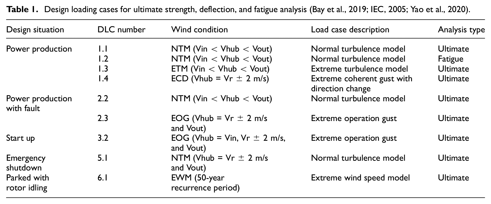
Based on the IEC standard 61400-1, different load cases were simulated in OpenFAST (Jonkman et al., 2005), including power production cases, fault cases, start up cases, emergency shutdown cases, and parked cases. Table 1 lists the design loading cases used for SUMR50 design (Kianbakh et al., 2021).
Design loading cases for ultimate strength, deflection, and fatigue analysis (Bay et al., 2019; IEC, 2005; Yao et al., 2020).
Based on IEC and GL standards, by considering all partial safety factors for loads and composite materials, the safety factor for ultimate strength analysis under normal load was determined to be 2.977, the safety factor for fatigue calculations was 1.634, and the buckling analysis was 2.042, as in Table 2, which were consistent with studies by Griffith and Ashwill (2011) and Yao et al. (2019, 2020, 2021).
Combined materials and loads safety factors for SUMR50 (Griffith and Ashwill, 2011; Yao et al., 2020).

AutoNuMAD Monte Carlo optimization
AutoNuMAD (Chetan et al., 2019a, 2019b; Yao et al., 2021) is a semi-automated blade design tool under development at the University of Texas at Dallas, this tool was built based on a detailed structural design tool (NuMAD) developed by Sandia National Laboratories (Berg and Resor, 2012). In the AutoNuMAD framework, various blade structural parameters could be defined to generate the detailed structural models, which would be used as an input for OpenFAST to perform aeroelastic simulation (Mendoza et al., 2021a), as demonstrated in Figure 2. MLife (Hayman, 2012) was also coupled with AutoNuMAD to post-process the blade fatigue performance. Within this AutoNuMAD framework, the detailed blade structure could be optimized through either Monte Carlo simulationa or an optimizer, with respect to the blade mass/cost, static and dynamic performance of the wind turbine (Chen et al., 2021; Tang et al., 2021).
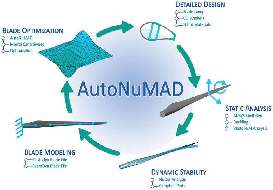
AutoNuMAD framework (Chetan et al., 2019a).
Aero-structural optimization
The initial aero-structural trade study provides a direction for an optimal aero-structural design solution; the aerodynamic team provides a set of optimized aerodynamic design candidates based on previous trade studies, these aerodynamic candidates are mapped to AutoNuMAD for structural optimization to achieve an optimal aero-structural design solution to realize a mass/cost-effective 50 MW downwind wind turbine rotor.
SUMR50 baseline structural design study
This section discusses the initial conventional design to provide a close to working level structural design; AutoNuMAD is applied to the close to working level structural design to optimize the root and spar cap to realize an optimal working baseline design. The detailed SUMR50 baseline design specifications are provided and a comparison for a series of blade structural designs for downwind rotors (including SUMR13A/B/C (Pao et al., 2021; Yao et al., 2021) for a 13 MW rotor, SUMR-D (Bay et al., 2019; Yao et al., 2020) for a 20% scaled demonstrator of the SUMR13i, and SUMR50 (Kianbakh et al., 2021) for a 50 MW rotor) is also presented.
Initial conventional design
Once the initial blade aerodynamic definition for a 50 MW rotor was defined, the initial structural layup was established based on SUMR13C (Yao et al., 2021) and SUMR25 (Qin et al., 2020) structural layup designs. NuMAD was used for the detailed structural design; OpenFAST, MLife, and ANSYS were used for the structural performance analysis.
Two initial structural designs (SUMR50_S1 and SUMR50_S2) were scaled models for tuning the control. From SUMR50_S3, we had a blade with a length of 236 m, which yielded a blade structural design with a mass over 372,000 kg. Figure 3 shows the structural architecture of the 236-m blade design, which contains five shear webs to help resist the buckling caused by the larger panel and high loading. To further increase the energy capture, SUMR50_S4 was designd to have a blade length of 250 m and a blade mass over 450,000 kg, the extreme high mass produced a significant inboard bending moment. Due to the high loading in the blade inboard area, the fatigue life for the inboard area was less than the 20 years requirement (Griffith and Ashwill, 2011; Yao et al., 2020). To improve the inboard structural performance, the spar cap and root section were redesigned for the 250-m length blade. The detailed study is described in the following sections.

NuMAD structural design demonstration for the 236-m blade design (SUMR50_S3).
Spar cap and root Monte Carlo studies
To design a blade with the length over 200 m, the extreme-size and high self-weight establish a significant challenge for the structural design, which results in a high root bending moment and a high cost in price (mostly due to the high usage of expensive carbon fiber). To reduce the cost and address the inboard performance shortage in the 250-m SUMR50 blade, the spar cap was optimized and the root design was investigated.
Spar cap Monte Carlo study
Monte Carlo simulation method within AutoNuMAD platform was applied to optimize the spar cap design for the 250-m SUMR50 blade. DLC 2.3 was determined to be the extreme design loading case, which yielded a maximum combined root bending moment of 1,154,478 kN-m that was about 10 times of SUMR13C blade maximum combined root bending moment (Yao et al., 2021). The carbon (carbon fiber reinforced polymer (CFRP)) spar cap was selected as the design variable due to its significant contributions to both structural performance and blade cost. The maximum allowable tip deflection and baseline blade mass were applied as the reference performance during the process, 43 m was calculated as the maximum allowable tip deflection to avoid a tower strike, and current mass was used as the mass upbound.
Figure 4 presents the designs after the spar cap Monte Carlo simulation, the blue dots represent the blade designs with different spar cap layup designs, the horizontal red solid line stands for the blade maximum allowable tip deflection to avoid a tower strike, the vertical yellow solid line shows the current baseline blade mass. A couple of designs, which were below horizontal red solid line and on the left side of the vertical yellow solid line, were selected as the design candidates for further investigation, these designs were selected based on a comprehensive evaluation of tip deflection, total blade mass, and mass center. The optimal blade design should satisfy the tip deflection requirements with minimum carbon consumption, meanwhile, the mass center should be in a more inboard (lower) position to reduce inboard loading due to the gravitational loading. Thus, among the above-mentioned design candidates, a design with the spar cap layup could potentially provide a lower mass center was selected as the design candidate for the next design iteration. From this design iteration, we minimized the usage of carbon, maintained the structure performance and kept the mass center at a lower position, lower mass center design could reduce the edge-wise root bending moment due to the gravity effect.

Design candidates from AutoNuMAD spar cap Monte Carlo simulation.
Root fatigue Monte Carlo study
As mentioned before, the current 250-m SUMR50 design (SUMR50_S4) had a shortage in inboard fatigue life, which was less than 20 years. The previous study has optimized the blade structure based on the static analysis, in this part, different inboard structure designs are investigated to improve the inboard fatigue performance.
To improve the structure performance of the blade inboard section, one approach is to increase the root diameter, another way is to put more materials in the root section. As discussed in (Yao et al., 2021), the optimal design solution could combine optimizing the structure layup and root sizing optimization, by exploring the design space between changing the root diameter and the material usage, we optimized the root structure design to have good fatigue performance and minimal material usage.
The blade dynamic performance under normal turbulence conditions from cut-in wind speed to cut-out wind speed was evaluated by OpenFAST simulations, and then the resulted data was post-processed by MLife to calculate the fatigue performance of the wind turbine. However, the whole process of OpenFAST simulations for one structural design could take a few hours, but MLife post-process might only take a few minutes. Thus, if only MLife was used to evaluate the fatigue performance, the time for each design iteration could be significantly reduced. Based on the above-mentioned idea, the possibility to use only MLife for the root fatigue study was inspected.
First, we studied the root stiffness impact on fatigue life without the full OpenFAST simulation, two approaches were applied:
Cases 1–5: trailing edge (TE) reinforcement around max chord (23%, 26% span) was increased to 20 layers (from 6 layers); Case 1 has a root diameter of 11 m, Case 2 has a root diameter of 12 m, Case 3 has a root diameter of 13 m, Case 4 has a root diameter of 14 m, Case 5 has a root diameter of 15 m;
Case 6, the root buildup thickness was increased by 50%, the root diameter was the same as the current SUMR50 design (11.3 m).
Based on the above six design cases, first, we used the OpenFAST simulation outputs from current SUMR50 blade design with a root diameter of 11.3 m and modified the associated structure properties for the above six cases in the MLife input files, then ran MLife based on the same OpenFAST simulation outputs with updated MLife input files to get the fatigue life for all above-mentioned cases, this process was named as frozen OpenFAST simulation. Next, we re-ran the full OpenFAST simulations and MLife for the above six cases to get the fatigue performance for all cases, this process was the regular analysis process (updated OpenFAST simulation). Thus, we have two sets of fatigue life data for each case, one is based on the frozen OpenFAST simulation outputs, with updated MLife inputs; the other one is based on updated OpenFAST simulation outputs and updated MLife inputs. We compared the two sets of fatigue results to get the error percentage for this method.
Among the first five cases, Case 2 with 12-m root diameter provided the smallest errors between frozen data set and updated data set, the maximum error was around 15%, which happened at the 12-m span location. Case 6, in which we only modified the materials layup and kept the root diameter as 11.3 m, had a maximum error of about 30%, which happened at 12-m span location as well. The fatigue performance error between frozen data set and updated data set was at a reasonable level by considering the simulation time we can save.
From the above study, the proposed simplified fatigue study approach was promising. A new design with a root diameter of 12 m was selected due to its relatively small error, and its material layups in the root area were used as the design variable to run MLife based (frozen OpenFAST simulation) AutoNuMAD Monte Carlo simulations. In each simulation, the MLife input was updated for every new structural design, but the OpenFAST simulation was kept the same.
The results of MLife based AutoNuMAD fatigue Monte Carlo simulation (frozen OpenFAST simulation) for span location 1 (12.5 m from root) are presented in Figure 5 and for span location 2 (37.5 m from root) are presented in Figure 6. The edge-wise fatigue performance of all designs for location 1 and 2 is in Figures 5(a) and 6(a), and the flap-wise fatigue performance for all designs for location 1 and 2 is in Figures 5(b) and 6(b), these results show that the inboard edge-wise fatigue performance is the design driver for extreme-scale blade, which follow the same trend of previous study (Yao et al., 2021). By considering the potential error in this method based on the study in previous section, a minimum edge-wise fatigue life of 50 years was selected as the design constraint for both span location 1 and span location 2, the green dots in the figures were selected as the optimal design candidates, which met the design constraint for both locations and maintained relative lower blade mass.

Fatigue Monte Carlo simulation for span location 1 (12.5 m from root): (a) edge-wise fatigue life and (b) flap-wise fatigue life.

Fatigue Monte Carlo simulation for span location 2 (37.5 m from root): (a) edge-wise fatigue life and (b) flap-wise fatigue life.
A new root layup design was selected from the MLife based AutoNuMAD fatigue Monte Carlo simulation by considering the 50 years minimum fatigue life, the structural mass and smoothness of the layup transition, the new design had a edge-wise fatigue life of 165 years at span location 1, and 70.5 years at span location 2. Meanwhile, the OpenFAST simulation was updated based on the new structural design to calculate the updated fatigue performance for this design, which resulted in a edge-wise fatigue life of 138 years at span location 1 and 68 years at the span location 2. They matched pretty well with the results from the results based on the frozen OpenFAST simulation method and the errors were much lower than what we expected, which proved the feasibility of the root fatigue study based on the proposed frozen OpenFAST simulation method.
Summary of spar cap and root optimization study
In the spar cap study, the spar cap was redesigned to reduce the blade cost; at the same time, in the root study, the inboard fatigue life has been improved over 20 years successfully. Combined the results from both spar cap study and root study, a new 250-m SUMR50 (named as SUMR50_S5) blade structural design was provided. The new design had a blade mass of 502,000 kg, it should be noted that the added mass was mainly contributed by the root build up that made primarily of the glass fiber, the high price carbon usage was reduced significantly. Also, the mass center for the new design shifted toward inboard by over 10 m comparing to the previous 250-m SUMR50 structural design (SUMR50_S4), the inboard edge-wise loading for the new design was also reduced, which further helped us to improve the root fatigue performance.
We re-checked the performance of the SUMR50_S5 blade design and found the minimum fatigue life was 554 years at span location 2 (37 m from root), which occurred in the edge-wise direction. The inboard fatigue performance has been improved significantly, due to the reduced inboard edge-wise loading (more inboard mass center) and improved root design. SUMR50_S5 was considered as SUMR50 baseline blade structural design.
The above-mentioned AutoNuMAD Monte Carlo simulations for spar cap and root were performed separately and based on a pre-defined aerodynamic design, which might produce a sub-optimal solution. Thus, in the following part of the paper, we couple the aerodynamic design and structural optimization into a whole design and optimization process.
SUMR50 baseline structural specifications and discussion
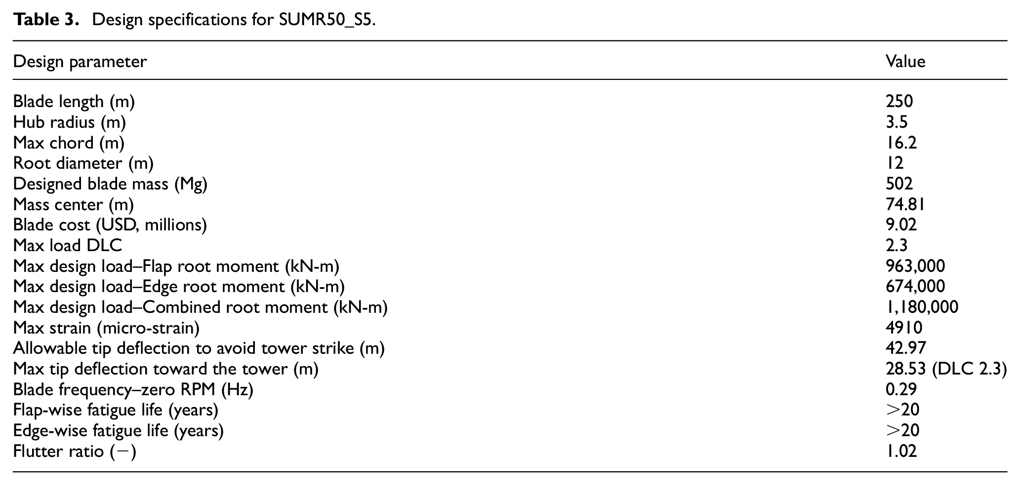
Table 3 provides the detailed design specification for SUMR50_S5. After the spar cap and root fatigue Monte Carlo simulations, this design with improved spar cap and root (inboard) designs have fatigue life greater than the 20-year requirement for both flap-wise and edge-wise directions. As expected, the edge-wise fatigue life was the more limiting factor for this truly ultra-scale blade due to the large cyclic gravitational loading. Based on the calculation in ANSYS, the maximum strain is 4910 micro-strain as shown in Table 3, which occurs at the flap-wise panel. The discussions about the logistical challenges for such an extreme-scale blade, and specifications comparison for a series of two-bladed downwind blades are provided in the following part.
Design specifications for SUMR50_S5.
SUMR50 logistical challenge
The extreme-scale of the SUMR50 blade enhances existing logistical wind turbine blade challenges and it also creates new ones due to its innovative but sheer dimensions. Some of these challenges can be classified under the following categories and are described in more detail below (Mendoza et al., 2021b).
Manufacturability: A 250-m blade represents an extreme challenge regarding manufacturability. Aspects such as maintaining good quality control of layer orientation and of cured laminate thickness, fabricating large and expensive molds that have good return on investment, and constructing a manufacturing facility able to cover the full span and chord of the blade are some of challenges that current blades already have but the problem becomes enormously more expensive and difficult to resolve for a 250-m blade which is more than twice as long as the longest blade manufactured to date (107 m (GE, 2019)). Alternative solutions to make the manufacturing of the SUMR50 blade more feasible include segmenting the blade into pieces.
Transportation: A single piece (monolithic) SUMR50 blade could not be transported through US highways while meeting state regulations due to its sheer chord and length. Transportation by air would also be extremely difficult or impossible as well as expensive given the enormous SUMR50 blade mass of 502 metric tons. Currently the largest air transport is the Antonov An-225 Mriya that can carry a payload of up to approximately 247 metric tons but the cargo aircraft only has length of 84 m (ANTONOV, 2016). Ocean transportation is the least restricted type of transportation in terms of cargo dimensions and mass, thus it is the most viable option for transportation of the SUMR50 rotor blades.
Installation, Inspection, and Repair: Due to the extremely tall tower, not only it is a gargantuan/impossible challenge to lift and install the monolithic rotor blades, but also the rest of the rotor-nacelle assembly and the top tower sections. A 250-m blade, equivalent to the length of approximately 2.5 football fields, would also be difficult to inspect and repair given its large surface area.
SUMR-D, SUMR13A/B/C, SUMR50 comparison
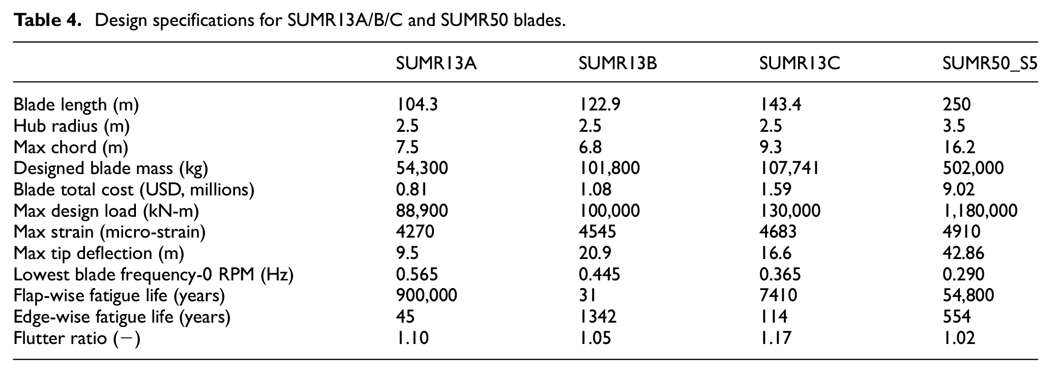
Table 4 lists the detailed specifications for SUMR13A, SUMR13B, SUMR13C (Yao et al., 2021), and SUMR50, and Figure 7 provides a cumulative mass/cost along the blade span comparison among SUMR13A, SUMR13C, and SUMR50. From above comparisons, we can notice the loading on SUMR50 has been increased significantly comparing to previous designs; the edge-wise fatigue limits the structural fatigue performance for the large(extreme)-scale blade. As in Figure 7(a), from SUMR13A to SUMR50_S5, the larger the blade is, the higher cumulative inboard blade mass ratio we can notice; Figure 7(b) shows pretty similar cumulative blade materials cost ratio along the span. SUMR50_S5 will be used as a SUMR50 baseline for further discussion and optimization study.
Design specifications for SUMR13A/B/C and SUMR50 blades.

Normalized cumulative mass and materials cost along the blade span compare among SUMR13A SUMR13C, and SUMR50: (a) normalized cumulative mass and (b) normalized cumulative materials cost.
Rotor mass projection
In Figure 8, we list rotor mass corresponding to the rotor radius for the current commercial and research wind turbines (Griffith and Richards, 2014; Yao et al., 2021), here, the rotor radius is the blade length plus hub radius and the rotor mass is the total mass of all blades of a rotor. The rotor mass from Segmented Ultralight Morphing Rotor (SUMR) project falls in the area below the high innovation projection. In detail, the trend line is for understanding the rotor mass trend. For the conventional rotor mass projection, the rotor mass follows radius ratio (Investigated Rotor/NREL 5 MW) to the power 3; for some high innovation rotor mass projection, which includes most currently GE Halidade-X rotor, they follow radius ratio (Investigated Rotor/NREL 5 MW) to the power 2.2. The power factor for the SUMR rotor design is at around 1.8, which shows the advantage of the SUMR downwind rotor structural design in regard to the mass and cost savings relative to the high innovation projection (green line). SUMR50 baseline rotor mass is between high innovation projection and SUMR projection, which may tell us SUMR50 rotor mass could be further optimized.

Rotor mass studies and projections versus rotor radius.
AutoNuMAD aero-structural optimization
As mentioned before, SUMR50 rotor mass could be further optimized. Optimization of aerodynamic and structural design is critical for an efficient wind turbine rotor design, and especially for extreme-scale (e.g. 50 MW) rotors. In this section, we examine the aero-structural design space to realize an optimal aero-structural design solution for a blade working for 50 MW rotors. The design spaces include varying airfoil thicknesses and blade chord sizes, which have major impacts on both aerodynamics (power and loads) and structural properties (blade strength and stiffness). First, we perform initial study to investigate the design space for different aero-structural options; then a new set of aerodynamic designs is provided based on the previous study; AutoNuMAD based Monte Carlo structural optimization is performed to achieve a mass/cost-effective aero-structural solution.
Initial aero-structural sensitivity study
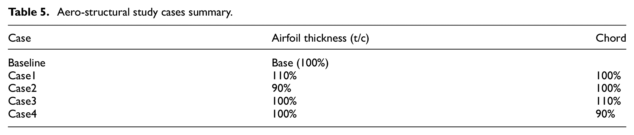
To mitigate the possibility of a sub-optimal solution, aerodynamic and structural design were coupled to further explore an optimal design solution for a 50 MW wind turbine blade. At the initial stage of the design process, the sensitivity study was performed to understand the design trend and narrow down the design selections to reduce the computational expenses. Five cases with different blade geometries including the baseline were investigated, as described in Table 5 and Figure 9. Case 1 is airfoil thickness increased by 10%, and maintains the same chord distribution; Case 2 is airfoil thickness reduced by 10%, and maintains the same chord distribution; Case 3 is chord size increased by 10%, and maintains the same airfoil thickness; Case 4 is chord size reduced by 10%, and maintains the same airfoil thickness.
Aero-structural study cases summary.

Aero-structural design space demonstration for SUMR50.
Figure 9 describes the potential optimal design solutions we can achieve through the aero-structural design. At the center of the figure, the baseline SUMR50 design is provided, around the baseline design, the four aero-structural design cases are described. The results of four aero-structural study cases could indicate a design direction to achieve an optimal solution, and the optimal solution could be an intermediate design shown in Figure 9.
Figure 10 shows a represented comparison between the original airfoil and a redesigned airfoil, the middle one is the original airfoil used in the baseline design, the Case that is that is the new airfoil with a thickness of 10% increase is outside of the baseline, and the Case 2 that is the new airfoil with a thickness of 10% decrease is inside of the baseline. Figure 11 shows a represented comparison between the original chord distribution and a redesigned chord distributions along the blade span, the middle one is the original chord distribution in the baseline design, the top one is the new chord distribution with a chord size of approximately 10% increase (Case 3) and the bottom one is the new chord distribution with a chord size of approximately 10% decrease (Case 4).

Represented comparison between original airfoil thickness and a redesigned airfoil thickness.

Represented comparison between original chord distribution and redesigned chord distribution.
Figure 12 shows the maximum blade tip deflection toward the tower for all five cases under different design loading cases (DLCs), the deflection should be maintained at a safety level to avoid a tower strike (allowable tip deflection for above-mentioned cases: 42.97 m). The results in the figure follow the trend that larger chord design has less tip deflection. The design with smaller airfoil thickness has much higher tip deflection than other designs, but the design with larger airfoil thickness does not show too many benefits in regard to reducing the tip deflection. Table 6 shows the detailed design specifications for the five cases in aero-structural sensitivity study.

Maximum tip deflection toward the tower under different design loading cases for different geometries.
Design scorecard for the aero-structural sensitivity study.
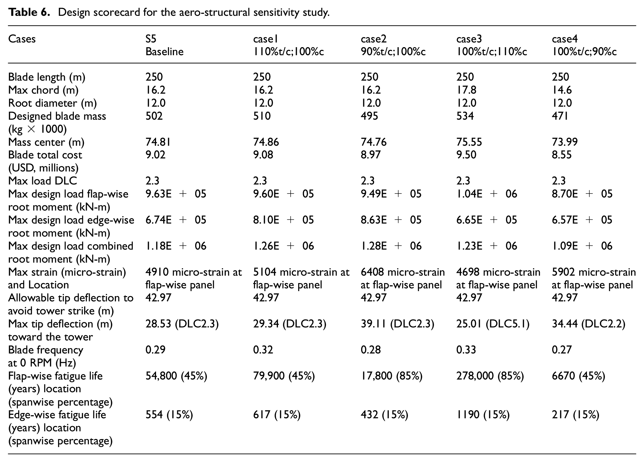
Figure 13 shows the percent changes of blade mass, blade cost, and blade maximum tip deflection toward the tower. Based on the results in the above figure and table, the Case 4 has largest saving in mass and cost, and maintains an acceptable level of maximum tip deflection toward the tower. From the initial study, the design with the smaller chord could potentially provide an optimal aero-structural design for a blade in a 50 MW wind turbine rotor.

Blade mass, cost, and tip deflection comparisons for the initial aero-structural sensitivity study cases.
Aerodynamic re-design
Based on the initial aero-structural sensitivity study, the design with smaller chord provided substantial benefits in mass and cost reduction and maintained an acceptable maximum tip deflection to avoid a tower strike, thus, a smaller chord design was preferable. The aerodynamic team provided three new aerodynamic blade designs with smaller chord sizes and maintained the rotor at the same rated power (50 MW). The chord distributions for the baseline design and the three new designs are in Figure 14. The Candidate Aero-structural Design 1 has less chord size and 1.29% blade length reduction comparing to the baseline design; the Candidate Aero-structural Design 2 (with 3.35% blade length increase), and the Candidate Aero-structural Design 3 (with 3.26% blade length increase) both have less inboard chord sizes, the Candidate Aero-structural Design 3 has an even smaller chord size than the Candidate Aero-structural Design 2.

Comparison of blade chord distributions for baseline and three candidate designs.
AutoNuMAD Monte Carlo optimization
AutoNuMAD has been applied in the design process (Chetan et al., 2019a, 2019b; Yao et al., 2021), the design process for the Candidate Aero-structural Design 1 is used as a representative example to demonstrate the design and optimization process; the other designs are following the same design and optimization strategy. Table 7 lists the span locations evaluated along the length of the blade, the evaluated stations covering from root 0% to 85% of the overall blade length.
Blade span fractions and locations for evaluations.
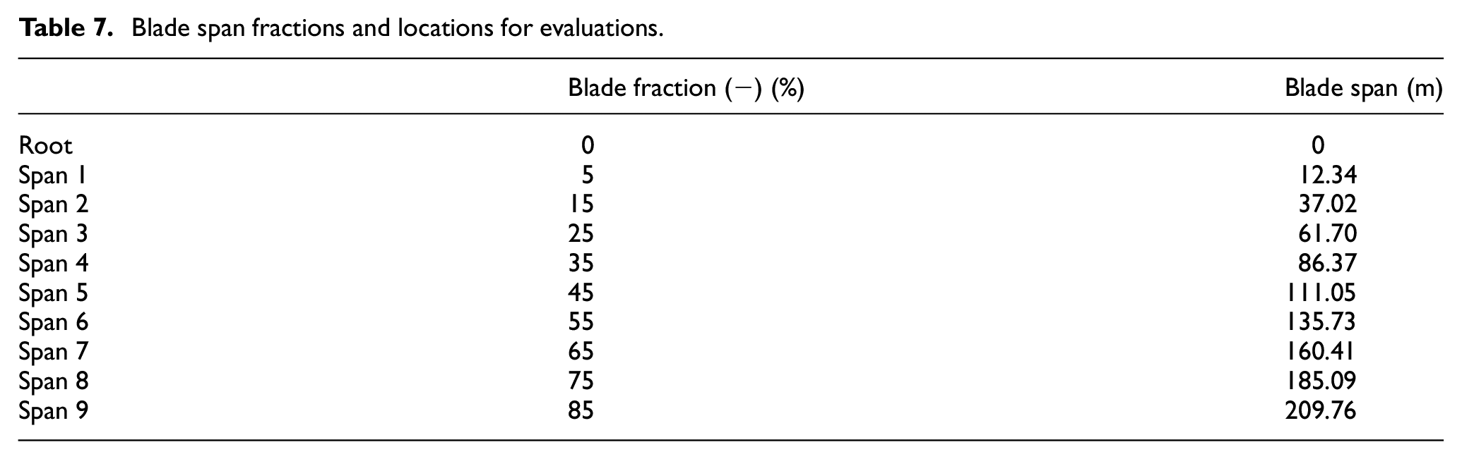
Table 8 compares the performance between the baseline design discussed previously and the Candidate Aero-structural Design 1_Base. The Candidate Aero-structural Design 1_Base is the design with the new aerodynamic design (Candidate Aero-structural Design 1) and the structural layups from the baseline design. The Candidate Aero-structural Design 1_Base yielded a 30% loading reduction and a 14% cost reduction. To further reduce the cost of the turbine, by adjusting the turbine configuration, including the overhang length, hub radius, and tilt angle (Griffith and Ashwill, 2011; Kianbakh et al., 2021; Yao et al., 2020), the allowable tip deflection to avoid the tower strike was increased by 47%. The new turbine configuration could direct to further mass and cost reduction.
Design specification comparison between SUMR50_S5 (baseline) and Candidate Aero-structural Design 1_Base.
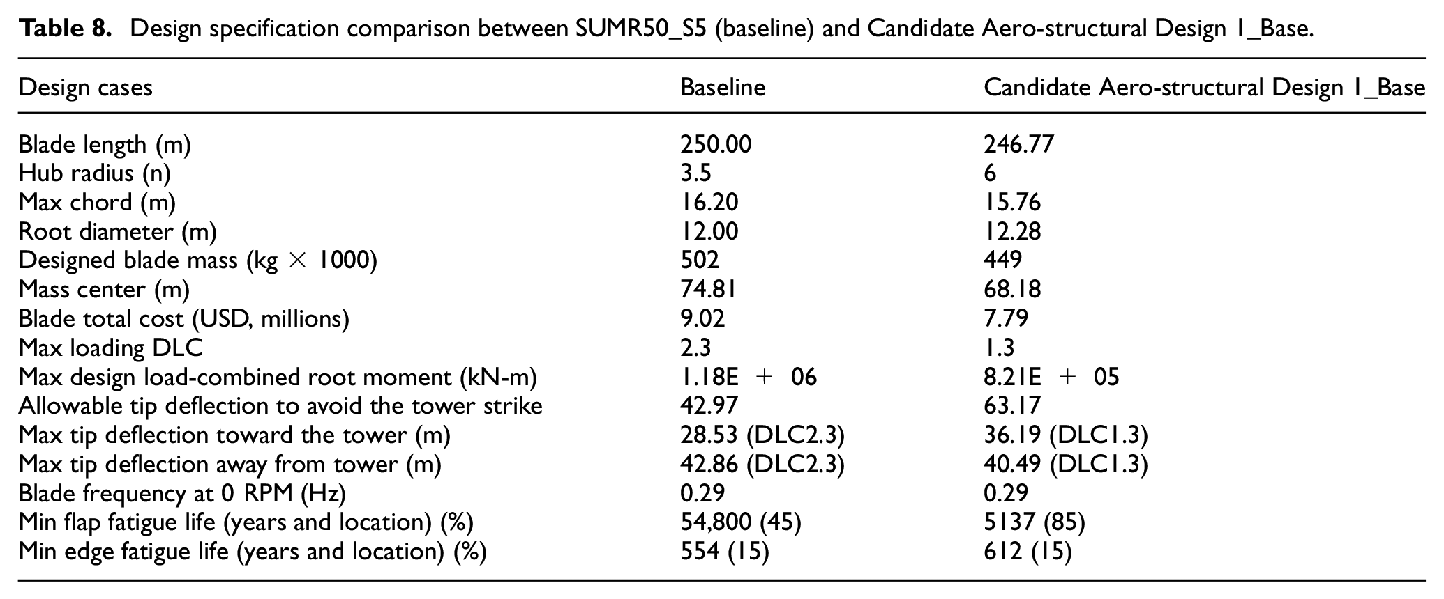
Based on Table 8 and the new turbine configuration, the Candidate Aero-structural Design 1_Base provided an over-designed deflection and fatigue performance, thus, further cost reduction could be achieved by pushing the maximum deflection and fatigue life close to the allowable limit.
The AutoNuMAD based Monte Carlo method was used to explore the design space. For the initial investigation, the Candidate Aero-structural Design 1_Base was considered as the new baseline, the design variable was the usage of carbon in the spar cap, which contributed significantly to the blade flap-wise performance and cost. Total 210 design cases with different spar cap layup designs were simulated.
Figure 15 shows the deflection (Y axis) as a function of the blade mass (X axis), the green crosses present the total 210 designs with different structural layups, the vertical yellow line is the baseline blade mass and horizontal blue line is deflection for the baseline design, the horizontal red line is the maximum allowable tip deflection toward the tower. To move forward in the design process, the designs showing deflections between 50 and 60 m were selected as the initial optimal design candidates; to downsize the design options, five of the initial design candidates were selected based on the simplicity and smoothness of the spar cap layups transitions for further fatigue performance evaluation.

The first Monte Carlo simulation for Candidate Aero-structural Design 1_Base.
For the selected five design candidates, the blade aeroelastic performance was calculated by OpenFAST and the fatigue performance was calculated by MLife for each design candidate, they all had good fatigue performance in edge-wise direction, since the spar cap thickness was the only design variable in this iteration. However, due to the extreme-scale and relative low carbon usage in the spar cap, the flap-wise fatigue life in span 5 and span 6 had some shortages (around middle span) for all design candidates.
The third design in the five design candidates was selected to move forward for next design iteration to improve the fatigue performance. The selection was based on the simplification of the structural layups transitions and relatively good fatigue performance. Thus, this new design was named as the Candidate Aero-structural Design 1_S1, which showed a safe level of maximum tip deflection but with some shortages in flap-wise fatigue performance, 9 years in span location 5 and 3 years in span location 6.
Next, AutoNuMAD coupled with MLife (frozen OpenFAST simulation) was used to perform Monte Carlo simulations to improve the flap-wise fatigue performance. MLife requires inputs from OpenFAST simulation, based on the IEC standard, DLC 1.2 should be used for the fatigue analysis, thus, normal turbulence wind cases with the wind speed from cut-in to cut-out are required. The full simulation is really time consuming, which needs couple hours for one structural design case, as mentioned before. Thus, a simplified AutoNuMAD Monte Carlo fatigue simulation with frozen OpenFAST simulation was used, which was similar to the above-mentioned root fatigue study. As was done before, the OpenFAST simulation was frozen, and MLife input file was updated for each structural design. Since only MLife was used in the process, the computational time was reduced significantly. Once the design satisfied the fatigue requirements, a full set of OpenFAST simulations for DLC 1.2 was performed to validate the results.
In Figure 16, the blue circles represent the different structural designs, with total 81 structural design cases used for the initial fatigue Monte Carlo simulation. In this iteration, none of the design satisfied the 20 years fatigue life requirement at span location 6. Thus, the design candidates (green dots) for the next design iteration were selected based on following criteria: (1) In span 5, the fatigue life was between 20 and 50 years (we had a very good agreement for this method in previous section, thus, the minimal fatigue life constraint could be relaxed); (2) In span 6, the fatigue life was above 15 years (no design with fatigue life above 20 years was identified for span 6 in this iteration). Among the selected designs (green dots), one design with best fatigue life in span 6 and least mass increasing was selected, such design had a fatigue life of 24 years in span 5 and 18 years in span 6. This design was named as Candidate Aero-structural Design 1_S2.

Monte Carlo simulations for flap-wise fatigue (span 5 and span 6) for Candidate Aero-structural Design 1_S2: (a) flap-wise fatigue life in span 5 and (b) flap-wise fatigue life in span 6.
Start from the Candidate Aero-structural Design 1_S2, further study was focused on fatigue performance at span 6, 16 cases were investigated. Figure 17 shows the designs with the fatigue life between 20 and 50 years (green dots) in span 6. The design with a fatigue life of 31 years was selected to move forward, such design was named as Candidate Aero-structural Design 1_S3. To validate the results and design, a full set of OpenFAST simulations of DLC 1.2 was performed and the results were post-processed by MLife, this design had a minimal fatigue life of 21 years, which occurred at span location 5.

Monte Carlo simulation for flap-wise fatigue in span 6 for Candidate Aero-structural Design 1_S3.
Figure 18 shows the spar cap layup distribution along the length of the blade for the designs in different design iterations. The initial design had a very thick spar cap layup as shown by the yellow line, such design had a much lower tip deflection than the calculated allowable tip deflection to avoid a tower strike. The Candidate Aero-structural Design 1_S1 was the design after the first Monte Carlo simulation for spar cap redesign, which had achieved a significant carbon usage reduction in the spar cap and maintained a safety level of tip deflection. However, the flap-wise fatigue performance for the Candidate Aero-structural Design 1_S1 needed to be improved in the middle span. Then two more fatigue-based Monte Carlo simulations were performed, after two trials of adjustments, the Candidate Aero-structural Design 1_S3 had satisfied both tip deflection and fatigue requirements. As seen in Figure 18, the Candidate Aero-structural Design 1_S3 has a thicker spar cap in the middle span.

Blade carbon spar cap thickness distribution along blade span change history.
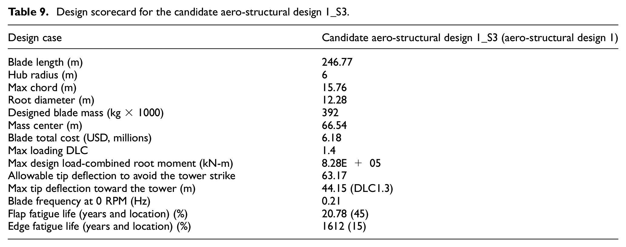
The detailed specifications for the Candidate Aero-structural Design 1_S3 are shown in Table 9, compared with the design specifications for the Candidate Aero-structural Design 1_Base in Table 8, 13% blade mass (from carbon) was reduced, and 21% blade total cost reduction was achieved. The flap-wise performance, including flap-wise tip deflection and flap-wise fatigue performance, was optimized to meet the design requirements. The Candidate Aero-structural Design 1_S3 was renamed as Aero-structural Design 1, meaning both aerodynamic design and structural design were optimized.
Design scorecard for the candidate aero-structural design 1_S3.
The detailed structural design optimization process for the Aero-structural Design 1 was demonstrated, the same design strategy was applied to the other two new aerodynamic design, the Candidate Aero-structural Design 2 and 3. The Candidate Aero-structural Design 2 and 3 have similar blade length (258 m), which is about 5% longer than the Candidate Aero-structural Design 1 (247 m), but have a smaller inboard chord size as shown in Figure 14. In addition, the Candidate Aero-structural Design 2 has a smaller chord size distribution along the blade span than the Candidate Aero-structural Design 3. After the similar Monte Carlo simulations for maximum tip deflection and fatigue performance within AutoNuMAD platform, the designs satisfied the initial structural design requirements. The detailed specifications for the Aero-structural Design 2 and the Aero-structural Design 3 are presented in Table 10.
Design scorecard for the aero-structural design 2 and 3.
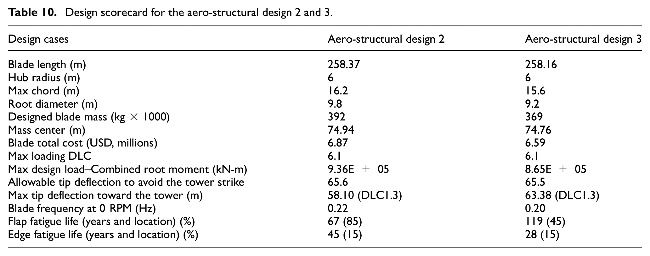
Among all three new aero-structural design candidates, the Aero-structural Design 3 shows the lowest blade mass, which is 6% lower than the Aero-structural Design 1, but the cost is 7% higher than the Aero-structural Design 1; comparing to the SUMR50 baseline (S5), the Aero-structural Design 3 has achieved 26% mass reduction and 27% blade total cost reduction. The Aero-structural Design 2 has higher blade mass and blade total cost than other two. Overall, the Aero-structural Design 1 shows a good structural performance, which has a good tip deflection, fatigue performance, and strength performance (with a maximum strain of 4287 micro-strain at flap-wise panel), also, it demonstrates the highest cost reduction, which is 32% comparing to the SUMR50_S5, and good mass reduction, which is 22% comparing to the SUMR50_S5.
Further economic study by using low-cost carbon
Significant amount of carbon was used in SUMR50 blade design to support high loading in both flap-wise and edge-wise directions, current carbon is Newport 307 carbon prepreg taken from Sandia-MSU Materials Database (Griffith, 2013a; Mandell and Samborsky, 1997). This type of carbon has a longitudinal modulus of 114.5 GPa and assumed unit cost of $26.40/kg (Griffith and Johanns, 2013). Some recent work done by Sandia National Laboratories (SNL) has provided optimized carbon fiber composites in wind turbine (Ennis et al., 2019), based on this study report, the unit cost of Industry Baseline CFRP pultrusion is $16.44/kg, and the unit cost of Heavy-Tow CFRP pultrusion is $11.01/kg for “current” scenario and $8.38/kg for “full-utilization” scenario; meanwhile, the longitudinal moduli for CFRPs in the report are better than Newport 307 carbon prepreg. Thus, if we replace the carbon in SUMR50 design by the new reported CFRP and assume the properties are not changed, the cost of carbon in the design could be reduced by 38%–68%.
Figure 19 provides the materials cost for each material used in the SUMR50 blade design (Aero-structural Design 1), the cost of carbon (Newport 307 carbon prepreg) is 67% of blade total materials cost, and the blade total materials cost is 63% of blade total cost (including materials cost, labor cost, and tooling cost). If the current carbon in SUMR50 design (Aero-structural Design 1) is replaced by optimized CFRP in the SNL report, with an assumption of the materials properties are not changed, thus, this scenario only impacts the blade materials cost:
Industry Baseline CFRP pultrusion: the total blade materials cost could be reduced by 25%, and the total blade cost could be reduced by 16%;
Heavy-Tow CFRP pultrusion in “current” scenario: the total blade materials cost could be reduced by 39%, and the total blade cost could be reduced by 25%;
Heavy-Tow CFRP pultrusion in “full-utilization” scenario: the total blade materials cost could be reduced by 46%, and the total blade cost could be reduced by 29%.
This study has provided a sense of how much cost reduction we can achieve by using optimized carbon in SNL report, to better understand the trade-offs among different types of carbon for the blade designs, more detailed redesign study by utilizing the new carbon in the design should be performed for further cost evaluations.

Aero-structural Design 1 materials cost breakdown.
Conclusions
An aero-structural design study was performed to achieve a 50 MW wind turbine rotor with a blade length of around 250 m. The initial study entailed the detailed structural design and performance of a baseline 250-m wind turbine blade for a 50 MW two-bladed downwind rotor. The baseline blade structural design was realized by AutoNuMAD (coupling with OpenFAST and MLife) Monte Carlo simulations. In the baseline design, the spar cap was designed to support high aerodynamic loading and the root was optimized to meet the critical edge-wise fatigue requirements. To further optimize the 50 MW rotor design, an aero-structural design and optimization study was performed. An initial aero-structural sensitivity study was conducted to explore the aero-structural design space by investigating different airfoil thickness designs and chord designs; subsequently, a set of three new aerodynamic designs was provided based on sensitivity study, and the structural design was optimized for each new aerodynamic design by utilizing AutoNuMAD Monte Carlo optimizer; the 50 MW blade design with the highest cost reduction through the aero-structural optimization was used for further cost reduction study by applying low-cost carbon. The key findings are summarized as follows:
We present a study to realize a 250-m wind turbine blade design for a two-bladed downwind 50 MW rotor. The carbon spar cap design, which was the major flap-wise loading component and cost driver, was optimized by AutoNuMAD Monte Carlo simulation coupling with OpenFAST; the root structural design experiencing high gravitational loading, which was the design driver for this extreme-scale wind turbine blade, was optimized by AutoNuMAD Monte Carlo simulation coupling with MLife to meet the fatigue performance in edge-wise direction. A baseline SUMR50 blade design (SUMR50_S5) was successfully designed to a working level by implementing the result from previous AutoNuMAD simulations, a design with more inboard gravity center could help to reduce the critical edge-wise loading;
An initial aero-structural sensitivity study was to explore the aero-structural design space by investigating different airfoil thickness designs and chord designs. Two airfoil options, including 10% thicker and 10% thinner, were investigated; two chord distribution options, including 10% larger and 10% smaller, were studied. A smaller chord design was selected for further aero-structural design and optimization study;
A set of three new aerodynamic designs was provided based on sensitivity study, the Candidate Aero-structural Design 1 was used to illustrated the design and optimization process, which included AutoNuMAD coupling with OpenFAST to optimize the tip deflection and AutoNuMAD coupling with MLife to realize an optimal fatigue performance. The Aero-structural Design 3 has the largest blade mass reduction (26%), and the Aero-structural Design 1 has the highest blade cost reduction (32%);
The Aero-structural Design 1 with the lowest blade cost was selected for further cost reduction study by considering the low-cost/optimized carbons. The blade total cost could be reduced by 16% using Industry Baseline CFRP (carbon fiber reinforced polymers) pultrusion, and over 25% by applying Heavy-Tow CFRP pultrusion.
Footnotes
Acknowledgements
The research presented herein was funded by the US Department of Energy Advanced Research Projects Agency-Energy (ARPA-E) under the Segmented Ultralight Morphing Rotor project (award number DE-AR0000667). The authors are grateful for the support of the ARPA-E program and staff. The authors also acknowledge the support of the entire SUMR team. The authors also appreciate the help of Jose Yumul Marquez and Mohammad Sadman Sakib from the University of Texas at Dallas. Any opinions, findings, and conclusions or recommendations expressed in this material are those of the authors and do not necessarily reflect the views of ARPA-E.
Declaration of conflicting interests
The author(s) declared no potential conflicts of interest with respect to the research, authorship, and/or publication of this article.
Funding
The author(s) disclosed receipt of the following financial support for the research, authorship, and/or publication of this article: This work was supported by the U.S. Department of Energy Advanced Research Projects Agency-Energy (ARPA-E) (award number DE-AR0000667).
