




Abstract
Renewable energy systems have experienced exponential growth toward producing zero-carbon energy. In this context, wind turbines continue to play a significant role. To extract maximum power, wind turbines are installed in array-like formation in wind farms. This arrangement though beneficial, also leads to detrimental wind-wakes effects. The wakes reduce wind speed and induce undesirable turbulence of flow field in downstream direction. To address this issue, several innovative techniques have been proposed. This paper surveys the best methods by classifying these into passive and active techniques. The passive techniques affect the wake flow by modifying only the geometrical or operating characteristics of wind turbines such as adjustment of forward and backward sweeps, etc. The active techniques use additional surfaces/devices for wake handling such as vortex generators, leading edge protuberances, dual-rotors, and cross-axis wind turbines etc. Additionally, this paper also reviews various wake measurement methods and recommends the best suited technique.
Keywords
Introduction
In the modern world, energy holds paramount significance in the development of nations. As anthropogenic warming of our planet reaches new highs, the need for provisioning of clean and green energy has become ever more significant. Since the start of industrial revolution, fossil fuels have remained the primary source for meeting global energy needs, however they emit harmful gases which has resulted in increase of global warming. Considering that the global community has agreed to control the environmental pollution by focusing on the development and usage of alternatives to fossil fuels to meet the UN SDGs, in particular the SDG 7 and 13 of “affordable and clean energy” and “climate action,” respectively (Galpern, 2021; Rhodes, 2016; Sahu, 2018; Viñuales et al., 2017). For decades now, renewable energies have been known for their superior potential to meet the world’s energy needs (Armaroli and Balzani, 2007; Ellabban et al., 2014). Of these the wind energy will likely meet about 35% of global power requirements by the year 2050 (Aravena et al., 2020; Singer et al., 2017; Tummala et al., 2016; Wiser et al., 2021). Therefore, significant research is being undertaken to fast-track the solution for design and optimization of wind energy system. In this context, various options to extract power from kinetic energy of air have been investigated, based on different types of turbines for both onshore and offshore locations. Recently researchers have further identified that offshore wind energy has significant potential as it has little, or no problem associated with sustained low wind speeds (Keivanpour et al., 2017; Sun et al., 2012; Wu et al., 2019). Moreover, depending on the nature of the flow field, different configurations such as HAWT, VAWT, and CAWT of wind turbines are being investigated and getting increasingly employed. As a result, these units are already producing significant power at much improved efficiencies (Kumar et al., 2018; Saad and Asmuin, 2014; Schaffarczyk, 2020). Nevertheless, the HAWT remains as the configuration of the first-choice for most onshore and offshore applications. Therefore, this review focuses on reviewing techniques that mitigate detrimental factors affecting HAWT operations, thereby maximizing performance and optimizing design of horizontal axis wind turbines.
Conceptually, the Betz theory places a limit of 59.3% on the maximum power that can be extracted by HAWTs from the kinetic energy of the wind. However, the current HAWTs do not meet Betz’s limit due to specific design constraints, system losses, and non-ideal flow conditions (Ragheb and Ragheb, 2011; Ranjbar et al., 2019). This has thus triggered research works that are focused on alternative design parameters to maximize power production from HAWT. The approach has been to identify factors that adversely affect the performance of HAWT and then work toward mitigating their causes. Until recently, many different factors have been identified. These include yaw-misalignment, noise generation, mechanical loads, blade design, wake interaction, etc.
To begin with, yaw-misalignment is a crucial factor that plays a vital role in degrading the performance of wind turbines (Bromm et al., 2018; Howland et al., 2020; van Dijk et al., 2016). Jing et al. (2020) have presented a better yaw misalignment detection method based on SCADA data for complex working conditions as the yaw misalignment affects the energy generation and quality of power. Ke et al. (2019) have presented this study for accurate load evaluation and responsive action mechanism for wind turbines under rainstorm conditions, focusing on blade yaw. Karakasis et al. (2016) have developed a yaw control, which is not affected by the inaccuracies incurred by vortex flow downstream of the rotor blades. Shen et al. (2019) have found a design technique to enhance the power extraction and life span of yaw system. The scheme works based on spatial correlations of wind direction. Li et al. (2019) have found out that the aerodynamic curves accompany the hysteresis effect for a yaw-oscillating airfoils. Furthermore, for accurate analysis of dynamic airfoil loads, it is essential to determine the dynamic characteristics of a yaw-oscillating airfoil. Wang et al. (2012) have compared six BEMT-based HAWT blades and found out that the morphing blades have better performance toward constant speed wind turbines than the pitch control ones. However, for variable speed wind turbine, the performance hardly improves for both pitch control and morphing blades. Dai et al. (2017) have loosely coupled unsteady RANS and Finite Element Method (FEM) for the aeroelastic modeling. Authors have established through computational modeling that average power and thrust decreases with increasing yaw angles. In contrast, the oscillation amplitude increases along with an increase in both the maximum deflection and strain under yaw condition. Wang et al. (2016) have calculated the aerodynamic loads via one-way coupling of CFD and FEA because the increase in the size and flexibility of turbine blades in wind turbines increases the importance of modeling of fluid-structure interface.
The noise generation is another common issue with large horizontal axis wind turbines (McKenna et al., 2016). Luo et al. (2015) has found that the generation of vortices in the flow field is related to noise generation and acoustic radiations, wherein its main resource area lies in the blade tip region. Moreover, to maximize the performance of wind turbines, different authors have examined several optimization techniques. Li et al. (2020a) have conducted MATLAB modeling and ANSYS simulations by taking strength, stiffness, noise reduction, and power generation into account. Authors have determined that the proposed optimization method can not only result in performance improvement but also reduction in the manufacturing and material costs of HAWT blades. Nandagopal and Narasimalu (2020) have optimized turbine blades of horizontal wind tidal turbines for maximizing the lift-to-drag ratio and lift coefficient without cavitation effects for flow conditions in the South East Asian region. Moshfeghi and Hur (2020) found out that changes in local AoA and relative velocities generate a complex 3D flow over the blades of wind turbine. The authors have proposed using split blades with a tip speed ratio of more than 3.5 as having higher power production than the No-split blade. Moreover, authors have also established that the split placed at the outer radius generates more power than at the inner radius. Li et al. (2020b) have extended the airfoil design optimization for low wind speed operations. Authors have determined a significant increase in lift coefficient and the lift-to-drag ratio of the established design along with a reduction in acoustic parameters by diminishing the performance sensitivity to surface roughness and inflow turbulence intensity. Tang et al. (2018) have optimized different wind turbines in a wind farm for maximum economic efficiency. Furthermore, maximum efficiency of wind farm has been achieved via different hub heights, variation in rotor diameters, and power generation characteristics.
Additionally, blade design is also an essential factor that influences the overall performance of the wind turbines. Researchers have employed different blade designs to increase the performance efficiency of wind turbines. Basom and Maughmer (2011) have used lifting-surface methodology using elements of distributed vorticity to implement potential flow to provide an improved prediction model for induced velocity distributions on the blade. Khalil et al. (2017) have used modified blade element momentum theory and CFD modeling to evaluate different aerodynamic design and analysis theories. Moghadassian and Sharma (2020) have presented a novel design of wind turbine blades that enhances the capturing of energy and reduces the blade loading. However, authors have determined that the blade design of a single turbine is different from a turbine installed in a farm. Lee and Kwon (2020) have used coupled CFD-CSD method for the structurally flexible blade on optimized rotor blades. The structurally flexible blade is also found to minimize the cost of electricity production. Hou et al. (2016) have used the PSO algorithm to optimize power dispatch strategy by considering both regular and irregular shape wind farms to maximize the power extraction. Ward and Jorba (2013) have found that reduction in power production and accompanying stress due to undesirable cyclic components are due to airflow below the horizontal axis. Newman et al. (2013) have studied the streamwise development of turbulence statics and kinetic energy by dividing the measurement plane divided into three regions: the above-rotor, rotor-swept, and below-rotor regions. Lee et al. (2016) have shown through CFD simulations that BEMT based blade has more maximum power coefficient than the other blade with constant chord length.
However, the most significant of all factors is the generation of wake downstream of the HAWT blades. Although, the wakes are not always bad, like Dabiri (2011) has investigated that the installation of counter rotating VAWTs in wind farm of HAWTs. He found out that there is an increase in power extraction per unit area when VAWTs are installed at downstream. This is because VAWTs have potential to extract power from wakes and also from above of the wind farm. Moreover, Ahmadi-Baloutaki et al. (2016) conducted wind tunnel experiments to study the aerodynamic interaction of VAWTs in wind turbine arrangements. They found out that counter-rotating VAWTs at the downstream of horizontal axis wind turbines increases the overall power output. In addition, the optimum distance between turbines was reduced to one rotor diameter with installation VAWTs in comparison to three rotor diameters in the absence of VAWTs. However, when the wind farms contain only HAWTs, then the wake not only causes detrimental effects on generating blades; moreover, it impinges upon HAWTs placed in downstream directions causing additional adverse effects. Therefore, one important technique is to reduce the wake generated by upstream wind turbines (Leung and Yang, 2012; McKay et al., 2013; Porté-Agel et al., 2020; Vermeer, 2001). The wake reduces the wind speed and induces turbulence downstream of wind turbines. The speed reduction in turn causes less power output from wind turbines in downstream direction. The effect of an upstream wind turbine on downstream wind turbines has been shown in Figure 1. Vaz and Wood (2018) examined Downstream HAWTs (DAWTs) via a novel technique by considering the diffuser efficiency and thrust parameters. Authors have formulated far-wake velocity and presented the correction for high rotor thrust.
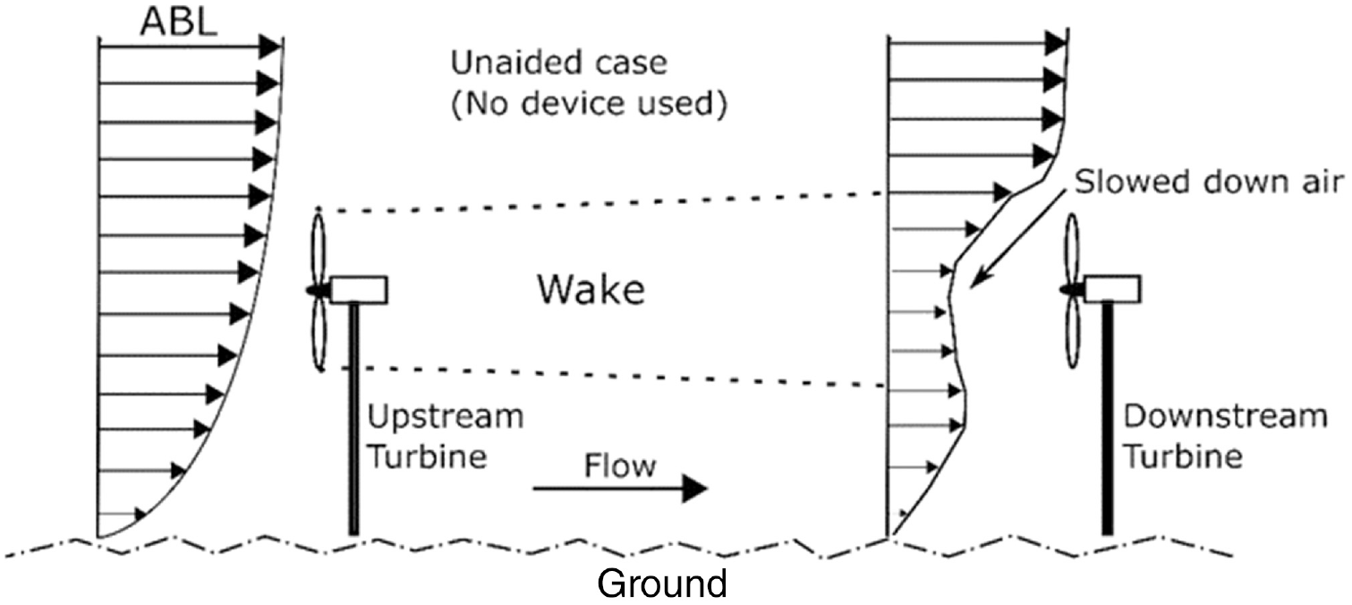
Effect of wake on downstream wind turbines in a wind farm (Bader et al., 2018).
The measurement/determination of wake behind wind turbines has been a contentious problem for some time now. Different authors have proposed several methods to accurately model, measure, or determine the wake phenomenon. In this context, the authors have used both numerical simulation and experimental methods. Ahmadi and Yang (2020) have studied the turbulence characteristics downstream of a turbine using simulations via LES coupled with the ALM. Lee and Lee (2020) have adopted NVLM to calculate aerodynamics loads of two small turbines. The method is found to help account for the effect of distortion, roll-up, and wake expansion. Branlard et al. (2013) have presented a new tip-loss correction parameter for the application in BEMT codes. Qian and Ishihara (2019) have employed MDDES and a hybrid framework to envisage the wake effects of the wind turbines in a complex terrain site. Chu and Chiang (2014) have measured turbulence intensity, time-averaged velocity, and Reynolds stress and compared the result for smooth flow and grid-generated turbulence flow. AbdelSalam and Ramalingam (2014) have examined the wake characteristics of the HAWT with an exact representation of rotor blades by using a steady-state RANS and K-
The reduction of aerodynamic wake is therefore a major problem area to reckon with. In this context, specific wake reduction strategies have been proposed by different authors to enhance the power production of wind turbines. This paper has reviewed different strategies proposed in recent years, which include the following: Chong et al. (2017) have presented a novel CAWT design to cancel the wake effect of HAWT blades by using vertical axis blades. Qi et al. (2021) have suggested adding a microplate in front of the turbine blade as a method to reduce the generation of wake. Kaya et al. (2018) have proposed a blade design by incorporating multiple sweeps start-up sections and tip offsets. Furthermore, Abdulrahim et al. (2015) have presented the concept of tip injection and the effect it has on the generation of wake. Zhang et al. (2020) have used TEF to control the aerodynamic properties, Hashemi Tari et al. (2016) have suggested a novel design of the rotor, and Vasel-Be-Hagh and Archer (2017) have taken hub height as an optimization parameter for maximizing power output. In addition to that, Yi-Nan et al. (2021) have studied the effects of LEPs on the flow characteristics, Nouri et al. (2020) have proposed that imposing the yaw angle to its rotor can steer away from the wake of wind turbine, and Ozbay et al. (2014) have proposed DRWT for controlling wake. Moreover, Tian et al. (2016) have presented a strategy to develop a passive flow control subsystem by applying VGs. Additionally, Li et al. (2015) have examined the impact of the separation distance between two turbines.
In this survey paper, the issues and detrimental effects generated by aerodynamic wake along with the possible mitigation techniques and latest trends in the measurement methods, as proposed by various authors, have been discussed. The particular focus is on identifying and analyzing the aptest techniques applied to reduce wake in various operating scenarios of horizontal axis wind turbines.
Phenomenon of wake
When a fluid moves around a solid body or when a solid body is moved through a fluid, it causes a disturbance in the fluid at locations downstream of the solid body. This disturbance is mainly caused by the separation of flow over solid surfaces. This disturbance is in the form of energized, random motion of fluid; thus, the flow is said to possess turbulence. Suppose the solid body imparts a rotational velocity on top of the axial flow and the turbulence that results in reduction of inflow velocity and attenuation in irregularities, then this phenomenon is known as wake (Dumitrescu and Cardos, 2004). Wake can be classified as either “rotational or irrotational.” The incoming flow transfers rotating torque to a solid body in a rotational wake. However, the body too transfers torque in return, this causes the flow to rotate resulting in a more complex flow field at downstream locations. This is the rotational wake generated behind the wind turbine, and it has an axial as well as tangential component of velocity. On the other hand, the irrotational wake is generally associated with straight flight or fixed solid bodies and it has less complexity than the rotational wake. As far as horizontal axis wind turbines are concerned, they have been significantly influenced by the rotational wake rather than from irrotational wakes.
Wind turbines extract power from the freestream wind. These turbines can have two or more blades, which rotate to harvest power. The rotation of blades induces rotational turbulence in the wind at the downstream location. This complex flow has significant effects on the overall performance of wind turbines. The energy downstream of the wind turbine is as a result of wake, which has substantial influence on the overall energy production of the wind farm (Li et al., 2021). The power harvested from a wind turbine strongly depends on the wind speed. The wake generated behind the wind turbines reduces the speed of the wind and imparts turbulence in the wind, therefore the downstream wind turbine face slow wind resulting in less power output (Cheng et al., 2019; Park and Law, 2015). It has been found that the average velocity deficit in wake region is around 30% which corresponds to about loss power coefficient of about 0.2 (McKay et al., 2013). Wakes affect aerodynamics and influence the structure and performance of wind turbine. Furthermore, the wake enhances the mechanical fatigue loads on the wind turbines resulting in reduced cost efficiency and hence the life of wind turbines (Liu et al., 2020).
The power parameter of the wind turbine can be converted to a dimensionless form for evaluating the relative performance of various HAWT configurations. The equation (1) describes

However, the maximum efficiency of wind turbines cannot exceed 59.3%, and this is known as Betz limit (Fadil and Ashari, 2017). The induction factor also has a significant effect on wake formation. When a = 1, at the downstream of the airscrew, a slipstream forms, which separates the wake from the external flow. These cylindrical vortex sheets generated due to vorticity constitute the slipstream boundary, and the wake rotates in angular direction. When at a = 0, the slipstream neither expands nor contracts and no energy is imparted to or from the flow. Korpela (2019) has explained that when freestream velocity “V” increases it transforms the pressure side of the blade to suction side, as a result, the airscrew extracts energy from the flow. In the case of wind turbines, the pressure increases at the surface of the blades and drops down across the blades. The work extracted is due to sudden drop in the static pressure. Therefore, the wind turbines operate in range of

Where,
For HAWTs placed downstream of other wind turbines the reduction in approaching wind speed due to wake effects emanating upstream, the power output from the wind turbine is significantly reduced. It has been explained by Joukowski’s analysis and is represented in equation (3) below.

Where, V is the freestream velocity,
Wake reduction techniques
In recent years, owing to unprecedented growth in the renewable energy sector across the world to meet the UN SGDs, there has been an increasing effort into solving wake problems in HAWTs. Hereinafter several methods are discussed. These methods involve “active” techniques—whereby additional surfaces or devices are employed on HAWT blades and “passive” techniques—that involve geometric or flow modification of blades to control the wake effects. These are enlisted below:
1. Active Techniques
a. Application of Microplate
b. Application of Cross Axis Wind Turbine
c. Application of Trailing Edge Flaps
d. Application of Leading-Edge Protuberances
e. Application of Dual Rotor Wind Turbines
f. Application of Vortex Generators
2. Passive Techniques
a. Application of Blade Sweeps
b. Improvements in Design of Rotor
c. Formation of Tip Vortices
d. Optimization of Hub Height
e. The influence of Yaw Angle
f. Optimization of Separation Distance
Active techniques
Application of microplate
Microplate refers to a microstructure placed in near the leading edge of turbine blades to induce vortices that can control the flow separation resulting into enhanced aerodynamic performance.
Purpose
Microplates inhibit flow separation on HAWT blades surfaces, especially at high AoA. As AoA increases, the trailing edge starting vortices tend to travel upwards that causes flow separation to begin from the TE of the blades. This separation of flow subsequently results in reduction of lift over the blade-aerofoil causing a degradation of the aerodynamic performance. This whole process leads to reduction in overall performance of the wind turbine. Qi et al. (2021) has applied micro-plate devices at the leading edge of blades which energized the flow over the blade surface resulting in a delay in flow separation and increasing the torque-to-lift ratio of the HAWT blades.
Technique and test method
Qi et al. (2021) have employed the micro-plate in front of the leading edge of the NERL phase VI wind turbine blades. The distance of the micro-plate is varied chord-wise and blade thickness directions; moreover, its width is also varied for investigation of optimal size and position on the blade. CFD simulation have been performed using RANS and
Results
Qi et al. (2021) evaluated the performance of HAWT blades by using the coefficient of performance (

Where, T is torque,
Application of cross axis wind turbine
CAWTs are designed on the concept of harvesting power from both the horizontal and vertical components of incoming air as they have two axes i.e., a horizontal axis and a cross axis. The Cross axis is perpendicular to the horizontal axis.
Purpose
CAWT can maximize the performance coefficient and minimize the skewed flow behavior and wake reduction in a single configuration. Conceptually, VAWTs have low power coefficients but have better performance in skewed flow conditions, whereas HAWTs have better power coefficients but face problems during operation under low wind speeds, and wind direction changes. Due to these limitations both VAWT and HAWT result in less power production. A combination of VAWT and HAWT is an innovative CAWT configuration proposed by Chong et al. (2017). The objective of CAWT is to combine the strengths of both types of wind turbines thereby extracting power from both vertical and horizontal components of the free stream wind. This results in combining the advantages of both HAWT and VAWT by diminishing their disadvantages. Moreover, CAWT use identical space as that of VAWT producing more power and performing better in multi-directional wind conditions.
Technique
The design proposed by Chong et al. (2017) consists of three vertical blades and six untwisted horizontal blades connected via specially designed connectors to provide robust structural integrity and larger swept area. To minimize the skewness in flow field downstream of HAWT, an additional velocity component is injected by VAWT, which induces a counter-skewness effect that minimizes the overall skewness in downstream flow. This technique also uses deflectors to guide the approaching wind upward, near the central region of cross axis wind turbine. Furthermore, airfoil-shaped struts have been used to reduce friction.
Test method: Chong et al. (2017) used a prototype of CAWT in which the pitch angle was varied from 0° to 15° with increment of 5° for the horizontal blades. Hence, four different configurations of CAWT have been used. This investigation employed an asymmetric NACA0015 airfoil profile with 15% thickness to chord ratio. The experimental study used 30° and 45° inclined deflectors. Chong et al. (2017) compared the results of CAWT performance with that of conventional straight-bladed VAWT.
Results
The results by of investigation have shown that the maximum
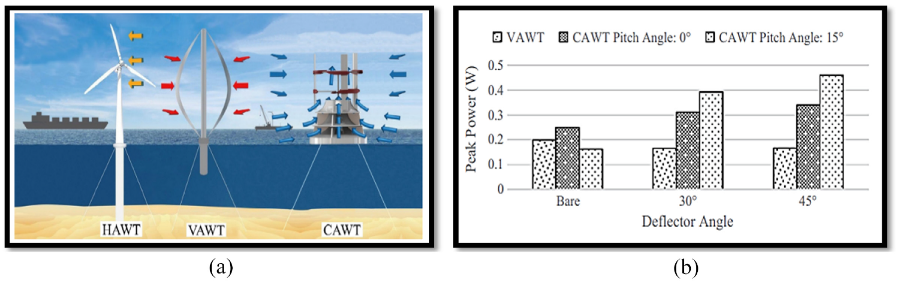
(a) configuration for HAWT, VAWT, and proposed CAWT model in offshore application and (b) the comparison of output power of different turbine with different pitch angles (Chong et al., 2017).
Application of trailing edge flaps
Trailing edge flaps or simply flaps are used to enhance the aerodynamic performance of the wind turbine by generating lift. The lift generated then reduces the fatigue loads.
Purpose
Large blades increase fatigue and load, leading to an increase in weight, cost consumption, and control difficulty. For load reduction, the traditional pitch control can adjust the aerodynamic properties of the blades. Among different technologies, the trailing edge flap (TEF) has significant advantage due to its simple structure and good high frequency regulating ability. The effect of TEF on wake development and power capture of wind turbines in wind farms has been studied in this paper.
Technique and test method
Computational domain, boundary conditions, smart rotor model with TEFs have been presented in this study by Zhang et al. (2020) and a numerical model. Nacelle and tower have great effect on the wake characteristics. Therefore, CFD simulations have been conducted by eliminating the nacelle and tower. The reference wind turbine was a 5 MW HAWT. Two wind turbines have been investigated at rated turbulent wind speed. Velocity has been used for analysis of HAWT wake. The velocity deficit has been examined for the level of wake width and velocity recovery. Computational method results were also verified in this study.
Results
It has been found by Zhang et al. (2020) that the deflection of TEF enhances the velocity deficit and decreases the wake width, which in term makes the wake more complicated. Moreover, the negative TEF angle has less influence than the positive angle. However, the downstream wake transforms into a triangular shape due to the presence of deflection that is induced by TEF. With a rated turbulent wind speed of 11.4 m/s, the total power growth of wind turbines reaches about 7.6%, while TEF of WT2 and WT1 are deflected at 0° and 6°, respectively. However, with a rated turbulent wind speed of 11.4 m/s, the total power growth of wind turbine reaches about 6.5%, while TEF of WT2 and WT1 are deflected at 6°. The results concluded that TEF has considerable influence on the power production and downstream wake characteristics, therefore it can be used to control the wind farm for maximum performance.
Application of leading-edge protuberances
Leading edge protuberances are applied on HAWT blade as a viable passive control method, which is very effective method for controlling the flow separation on the turbine blades. This, in turn, improves the aerodynamic performance of the wind turbines.
Purpose
To enhance the wind turbine’s aerodynamic performance by using an effective flow separation control method.
Yi-Nan et al. (2021) observed that the increase in wind turbine blades has substantial influence on flow separation, affecting the overall performance of the wind turbine. One of the passive flow control methods to enhance the aerodynamic efficiency of the turbine is the application of leading-edge protuberances (LEPs). It helps in lowering the drag and pitching moment, improving the stability of dynamic aerodynamic force, and reducing the aerodynamic force’s fluctuating intensity by refining the unstable features of airfoil aerodynamic in the stall area. The study of flow characteristics for the effects of LEPs is required via a theoretical model.
Technique and test method
Yi-Nan et al. (2021) have presented a novel technique to locate the LEPs on the blades as shown in Figure 3. At first, the effects of flow field were linked with the geometrical data of the LEPs, and potential flow function was resolved to obtain the forces created by the LEPs on the flow field. Secondly, Yi-Nan et al. (2021) has compared the solid airfoil containing LEPs with the flow and aerodynamic features of the model obtained by using N-S equations by substituting the momentum source into it. At last, the flow control mechanism of the LEPs was demonstrated by an innovative method that is, by developing a relationship between the distribution and flow separation of low-pressure area. The fluid has converted the aerodynamic force into a momentum source, convected downstream. The momentum sources in the x and y direction have been mentioned in equations (5) and (6), respectively.


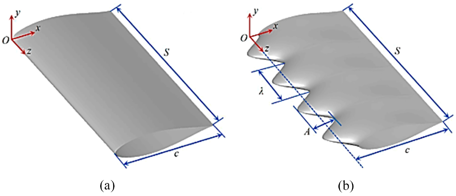
The model of airfoils used for the study: (a) baseline case and (b) the wavy case (Yi-Nan et al., 2021).
Where,
Results
The results of study by Yi-Nan et al. (2021) have shown that the area of low pressure in airfoil suction side is increased, enhancing the aerodynamic performance. In addition to that, good consistency is maintained by the proposed method under different stall conditions. Therefore, this study can be used in future for future investigation of the optimization and design of the flow separation control technology of LEPs.
Application of dual rotor wind turbines
DRWT consists of two rotors which are connected back-to-back. The air first passes through the primary rotor producing power followed by extracting the power by the secondary rotor.
Purpose
HAWTs are being used predominantly in the world to produce the electricity from wind energy. However, due to losses and non-ideal conditions, almost 50% of the wind energy passes the wind turbine rotors without being harnessed. Therefore, to enhance the power production capacity of the wind turbine, Ozbay et al. (2014) have proposed DRWTs to maximize the energy harvesting and to improve the durability of the wind turbine. This study by Ozbay et al. (2014) has analyzed the aerodynamic and wake characteristics of dual rotor wind turbines to improve their wind turbine performance.
Technique
DRWT have two back-to-back rotors. The energy from the upwind rotor is extracted first after which downwind rotor extracts power from unharnessed energy of incoming wind. As a result, DRWT has a significant increase in power output when compared with SRWT by almost 30% (Appa, 2002). It has also been found that power and wind loading fluctuations have a more significant effect on the spacing between the rotors than its effect on thrust and power coefficient. Ozbay et al. (2014) have compared the power production performance for three models, which are SRWT, DRWT (counter-rotating rotors), and DRWT (co-rotating rotors). The models of DRWT and SRWT have been shown in Figure 4.

The employed co- and counter rotating DRWT and SRWT models (Ozbay et al., 2014).
Test method
Wind tunnel tests have been performed in AABL. The turbulent boundary layer flow, comparable to the typical ABL, is generated by applying wooden blocks, spikes, chains, etc. on the wind tunnel floor. The typical hub height turbulence intensity of 0.12 has been used for experimental studies. The turbine blades have been made by rapid prototyping machine from hard plastic material. Aluminum rods have been used as towers, whereas output power from turbines has been measured by the generators placed inside the nacelle. Ozbay et al. (2014) have used the PIV technique for analyzing the turbulent near wake flow structure features. He also measured the dynamic and static loads acting on the wind turbines for both the DRWTs and SRWT.
Results
It has been found by Ozbay et al. (2014) that the dynamic and static loads along with power production performance of DRWTs were much higher than the SRWT. In addition to that, the co-rotating rotors have significantly lower power production than the counter-rotating rotors due to the exploitation of additional energy accompanied with the swirl flow of upwind by the downwind rotor. However, higher manufacturing costs and smaller life are associated with DRWTs due to enhanced static and dynamic loadings. In addition to that, higher velocity deficits have been found for DRWT in the near wake due to extraction of more energy from the incoming boundary layer wind. In contrast, DRWT produces great Reynolds shear stress and turbulent kinetic energy at the top tip level compared to the SRWT. Furthermore, Ozbay et al. (2014) have presented that the maximum values of swirling strength and vorticity were increased in both cases of DRWT in comparison with SRWT because of shedding tip and secondary vortices.
Application of vortex generators
VGs are aerodynamic devices attached to a lifting surface or a rotor blade to delay the flow separation and the aerodynamic stalling.
Purpose
The wind turbine performance needs to be improved over wide range of incoming wind conditions to reduce the cost of energy further. One way to achieve this is by regulating the flow separation and refining the rotor blade aerodynamics and the other way is to diminish the problems that occur from blade soiling. Tian et al. (2016) have presented a strategy to develop passive flow control sub-system to reduce the cost of electricity by enhancing the overall performance of the wind turbine, resulting in overcoming both aerodynamic and roughness issues.
Technique: The vortex generators can control the flow separation and problems related to blade roughness thus enhancing the power output by producing streamwise vortices. The generated streamwise vortices then increase the mixing between the local boundary layer and the freestream flow thus delaying the onset of stall.
Test method: Tian et al. (2016) have conducted wind tunnel experiments on two typical representative airfoils of the HAWT. The surface soiling effects have been modeled at blade leading edge to develop a roughness model to be solved by AcuSolve. The LEGR has been employed to determine the contamination effects on the airfoil performance, after which the airfoil is employed with both the LEGR and VGs. VGs produce counter-rotating vortices which are useful to overcome the problems that occur because of the roughness effects on the turbine leading edge. The VGs are placed at a 30% chord on the suction surface with 15° angle to the approaching flow.
Results: Tian et al. (2016) have found that LEGR can substantially reduce the performance by causing the airfoil to stall earlier with extra drag consequence, however these effects can be mitigated up to some extents by the application VGs. As VGs can increase the maximum lift by delaying stall, the current roughness model can provide accurate prediction about the aerodynamic coefficients, while it is not valid enough for prediction in post stall region. Therefore, a better configuration of VGs is also presented in this paper, which is in between 15% and 41% of the blade span. Moreover, it offers an increase of 1% in annual energy production.
Passive techniques
Application of blade sweeps
Blade sweep refers to an adaption of dynamic chord-wise balance when the tip of HAWT blade is moved forward or backward in its plane of rotation.
Purpose
Blade sweep is known to have a significant effect on aerodynamics performance leading to an increment in power coefficient of HAWT blades (Kaya et al., 2018). The aerodynamic performance of wind turbines plays a major role in harvesting the maximum power from wind energy. In this context, the blades play an essential role in the aerodynamic performance of wind turbines. Kaya et al. (2018) have investigated the incremental changes in the aerodynamic performance of wind turbines by adjusting sweep angles on the blades.
Technique and test method
Kaya et al. (2018) have incorporated the plane of the rotor with blade sweep. The blades are designed according to several tip offsets and sweep startup sections. Authors have employed CFD simulation to study the effects of forward and backward swept blades on the aerodynamic performance of HAWT. A blade offset equation, as defined in equation (7), is formulated which addresses the change in tip offset and sweep start up section. It calculates the offset at each blades section from the pitch line.

Where,
The simulations have been performed in moving frame reference on ANSYS Fluent 17.2. The study has been based on previous computational works of HAWTs (Krogstad and Lund, 2012; Sørensen et al., 2002). The results of power coefficient (CP) and thrust coefficient (
Results
Kaya et al. (2018) have determined that the forward swept blade has maximum power performance improvements with sweep start up at
Improvements in design of rotor
Rotor design plays a significant role in controlling the wake. Aerodynamic structure, turbine blade sweep area, and mean flow characteristics, etc., are some essential characteristics that influence the rotor design.
Purpose
Hashemi Tari et al. (2016) stated that the rotating wakes behind the HAWT can result in power loss. The upstream flow retardation is caused by the blade passage, which causes the opposite rotation due to the air passing through the rotor. In the near-wake region, tip vortices are generated by turbine blades, resulting in noise generation and blade vibration. In addition, the turbulent energy is generated in the near-wake to far-wake region, which decreases the life span of turbine rotors. Whereas, due to this, downstream turbine is subjected to low wind velocity. Authors have suggested that the design of rotor can be improved via vertical flow structure, mean flow characteristics, and turbulence characteristics.
Technique
This paper is focused to quantify turbulent and mean fields at various axial locations in the wake model. These outcomes can be substantial for understanding the physics of the flow in a rotating wake, primarily for the convection at downstream and mitigation of structure of the tip vortex. Hashemi Tari et al. (2016) checked the dissipation in wind turbine wake and the concentration point of highest shear, which are helpful in the interference study of wind turbines. The far-wake region has less influence of blade phase angle, which in turn can result in robust and simple wind farm models. This study is also helpful for studying the dynamic loads on the following turbine in the arrangement.
Test method
Wind tunnel experiments have been conducted by Hashemi Tari et al. (2016) to describe the turbulent flow structure of a HAWT. Flow field has been measured by particle image velocimetry (PIV) behind the rotor in the near-wake region.
Results
The radial span of 0.75 < r/R < 0.9 has the highest axial velocity deficit; therefore, the highest power extraction by the wind turbine occurred in this region. The expansion of wake occurs as soon the axial velocity has reached its highest value at the radial distance, which is greater than that of turbine’s actual radius. In addition, it is found that the helical vortex topology of near wake and the tip vortices are present in that region.
Formation of tip vortices
Tip injection is a technique in which high-energy jets are used to delay the occurrence of a stall by energizing the tip flow of any rotating machine.
Purpose
To minimize the adverse effect generated by flow field rotation to enhance the power production from a HAWT.
The performance of HAWT is significantly influenced by the rotation of flow field and formation of tip vortices which ultimately leads to a shear layer. The developed shear layer then separates the free stream flow from the rotor wake forming an extremely turbulent cylindrical shear layer. This influences the structural and performance parameters but also adversely affects the subsequent wind turbines. To curb this problem, Abdulrahim et al. (2015) have suggested a passive flow control method of tip injection, which in turn influences the turbulence characteristics, size, vorticity, and location of tip vortices and results in performance enhancement (Mercan et al., 2010, 2012).
Technique and test method
Abdulrahim et al. (2015) has conducted wind tunnel experiments with a three-bladed rotor having a 0.95 m diameter. The blades had NREL S826 airfoil profile, which are non-linearly tapered and twisted. Pressurized air is passed through the blade tip, while the blade is rotating. A servo motor has been used to control the speed of the turbine rotor. Moreover, it has been ensured that the air exits uniformly at the jet exit. The effect of tip injection is measured via constant temperature anemometry (CTA) measurements in the wake flow field. The results have been compared with the baseline case, with no injection.
Results
Abdulrahim et al. (2015) has found that with the tip speed ratio of less than 3.5, there is no effect on the power and thrust coefficients of the HAWT. However, tip injection has substantial effects on the thrust and power coefficient as shown in Figure 5, above tip speed ratio (TSR) of more than 3.5. At TSR = 4.5, the maximum thrust and power coefficients have been observed, which are about 19.5% and 27.3% more than that of baseline case, respectively. This shows that tip injection has a significant enhancement in the performance of HAWTs.
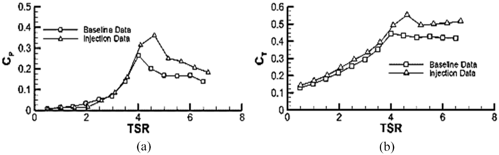
Comparison of thrust and power coefficient at free stream wind velocity of 5 m/s of (a) with tip injection and (b) without tip injection (Abdulrahim et al., 2015).
Optimization of hub height
The Hub height of a wind turbine is defined as the vertical distance between the center of the hub and the ground. The optimization of hub height refers to choosing the heights of wind turbines in a wind farm to harvest maximum energy from the wind.
Purpose
The power production of downstream wind turbines is significantly influenced by the adverse effects of the wakes generated by the upstream wind turbines thus reducing the overall power output of the wind farm. Hub height plays a vital role in overcoming the negative effects of the wind turbines. Therefore, study by Vasel-Be-Hagh and Archer (2017) optimized the hub height by unchanging the wind farm characteristics, base location, rotor diameter, etc. Previous studies have considered optimization of multiple parameters, which has prompted the authors to analyze the results of optimization of hub height only.
Technique and test method
Vasel-Be-Hagh and Archer (2017) has taken hub height as optimization parameter by conducting optimization investigation using GSA and the PARK wake model followed by the validation of PARK-based findings by four LES. This study is based on three cases. In the first case, only two wind turbines are considered, which have different hub heights and are aligned with the wind direction. In the second case, 20 large-scale wind turbines are examined, firstly with all wind turbines having height of 80 m. Secondly, with half turbines having hub height of 100 m and other half with 57.5 m. In the third case, a wind farm having 48 turbines have been analyzed using greedy search algorithm. Finally, the AEP has been examined for possible improvements with optimized hub heights of the turbines in the wind farm.
Results
For the first case, Vasel-Be-Hagh and Archer (2017) has found that two important effects of using multiple hub heights.. Firstly, by decreasing the hub height of the wind turbine rotors at downstream, they experience more undisturbed wind, therefore increasing the power output, and secondly, downstream wind turbines experience lower wind speeds due to wind shear. However, the spacing between turbines along with surface roughness on the blade can balance these effects. For the second case, using wind turbines with multiple hub heights produced 9.5% more power than wind turbines having same height. Lastly, the AEP of optimized wind farm arrangement, having multiple heights, enhanced by about 2%. Furthermore, the results have been validated by the LES results, and the authors propose that the optimization of hub heights can increase the power output, as shown in Figure 6.
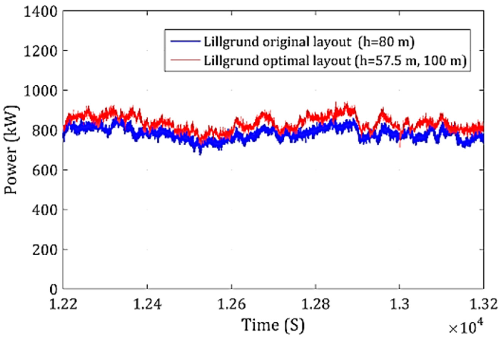
The power produced by original wind farm, and its optimized configuration with multiple hub heights (Vasel-Be-Hagh and Archer, 2017).
The influence of yaw angle
Yaw angle is basically an angle given to the turbine blades, such that the blade remains perpendicular to the incoming wind.
Purpose
Various sizes and quantities of wind turbines in the wind farm have been increased over the years. This have raised issues of major energy losses due to aerodynamic interaction of the wind turbines. One promising technique to overcome the negative effects of aerodynamic interactions of the wind turbines is the optimization and adjustment of yaw angle. Nouri et al. (2020) proposed that imposing the yaw angle to its rotor can steer away the wake of wind turbine from its downstream HAWTs. However, it is mainly based on non-zero angles to few or all upstream rotors. Therefore, the sign of the yaw angle has significant importance on the performance. The point to note here is that the yaw angle is only given to the turbine in the first row. The overall production of the column of wind turbines decreases due to the negative yaw angle of the front row turbine, however the positively yawed one enhances the power. The effects of yaw misalignments on the wake behind the upstream turbine as shown in Figure 7. The reasons for the difference can be the Coriolis effects and the clockwise turning of the turbine blades where the prior has a significant effect than the other.
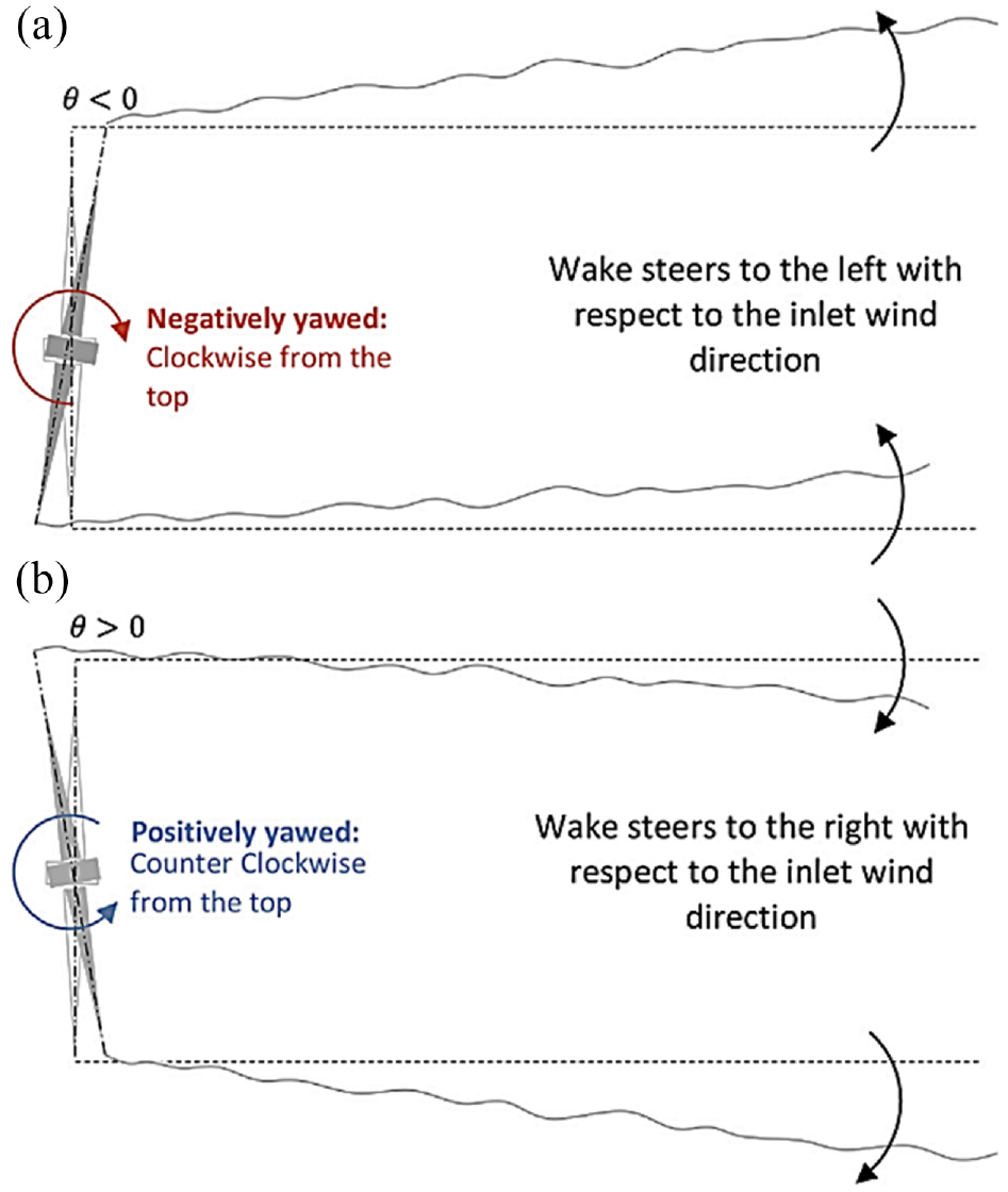
The effects the yaw misalignments on the wake behind the front-row turbine (Nouri et al., 2020).
Technique and test method
The yaw angle, Coriolis force, and the rotation of the wind turbines are varied to conduct six different LES to explore the two conceptual explanations explained above. These results by Nouri et al. (2020) have been found for wind turbines in northern hemisphere, and authors have suggested conducting another study to investigate these effects in the southern hemisphere. The authors have employed two columns and five rows of Siemens 2.3 MW turbines for this study. In case 1, all 10 turbines rotate clockwise by considering Coriolis forces, with perfectly normal alignment to the wind direction. While in case 2, the first turbine of each column is misaligned, one positively (+20°) and the other negatively (−20°), along with all 10 turbines rotating clockwise by considering Coriolis forces. Case 3 is like case 2, only the blades now rotate in counterclockwise direction. Whereas case 4 is same as case 1 but with Coriolis force set to zero. Case 5 is like case 2 but with Coriolis force equal to zero. Finally, in case 6, all 10 turbines rotate counterclockwise with Coriolis forces equal to 0.
Results
The results of the study conducted by Nouri et al. (2020) have shown that yawing angles, given to the turbine blades, cause the wake to steer. However, the positively and negatively yawing have different impacts on the output performance of the turbine blades. When the Coriolis force was set to zero with turbines rotating in clockwise direction, the difference between output power of wind turbine columns with positive and negative yaw misalignment reduced from 17% to 7%. When only the direction of turbine was changed from clockwise to counterclockwise, the difference reduced to 11%. However, when both effects were relaxed, the difference in the power production of positively-yawed and negatively-yawed wind turbine columns reduced to only 5.5%.
Optimization of separation distance
The separation distance is the distance between the upstream wind turbine and the adjacent downstream wind.
Purpose
To reduce energy loss due to increased turbulence and decreased velocity generated by the upstream wind turbines to enhance the efficiency of the wind farm.
Li et al. (2015) have presented that the wake generated by the upstream turbines significantly influences the power production of the downstream wind turbines. Therefore, there is a need to find an optimized distance between the wind turbines and it requires comprehensive knowledge of the wake interaction effects on wind turbines at downstream.
Technique
Li et al. (2015) have proposed that optimum distance between the in-line HAWTs can overcome the negative aspects of the wake, generated by upstream wind turbine, for the downstream wind turbine.
Test method
Li et al. (2015) have used RANS equations in CFD simulations to examine the impact of separation distance between two turbines on the downstream of wind turbine. FRM approach has been used to design. The vertical and lateral velocity distributions have also been presented by Li et al. (2015).
Results
Li et al. (2015) have found that the velocity defect in near-wake substantially depend on the turbine’s arrangement and the vertical and lateral velocity distributions. The appropriate distance has been found by Li et al. (2015) to be between 5D and 10D to weaken the wake effects of upstream winds to increase the velocity recovery speed. It has also been found that the wake width increases from 1.26D to 1.65D at distance of 1D downstream of the turbine.
Summary
To meet the United Nations Sustainable development goals, the world’s energy requirement should be successively fulfilled via renewable energy resources. Wind energy has paramount potential to help the world achieve the UN SDGs. However, as established by Betz’s limit, wind turbines cannot extract maximum energy from the wind. One primary reason is the wake generated by the upstream wind turbines, which effects the power extraction by the downstream wind turbines. Therefore, the wind turbines’ power enhancement and efficiency improvements can be achieved by diminishing the detrimental effects of the wake, which is generated behind turbine blades. The previous research works were carried out mainly on achieving the required power output performance and desired aerodynamic performance of wind turbines. In this paper, the recent advancements in wake reduction strategies have been successfully discussed in detail. The purpose, technique, test method, and results have been discussed for proposed wake reduction techniques. The paper includes proposed strategies to mitigate wake-based problems, their causes, and the solutions recently proposed by the authors. The proposed techniques have been mentioned below. Cross axis wind turbines have both the advantages of HAWT and VAWT as they overweigh the performance of conventional straight bladed HAWT and VAWT. The utilization rate of wind energy is reduced by flow separation on the surface of HAWT blade under high AoA. However, micro-plate can efficiently inhibit flow separation with a suitable arrangement in term of width and position. Swept blades with forward and backward sweeps are used to investigate the aerodynamic performance of HAWT. It is found that forward swept blades significantly enhance the power coefficient that is the performance, whereas backward swept blades result in reduction of thrust coefficient. The wake region of a model turbine with tip injection is investigated. The results have shown that the tip injection significantly influences the wake. The performance of downstream turbine is influenced by Trailing edge flap (TEF) devices. The wake becomes more complicated by reducing the velocity deficit and wake width for wind speed under 11.4 m/s by application of TEF. Blade phase angle significantly affects mean velocity and turbulence characteristics in near wake region closer to blade tip, and they become phase independent at downstream. It is found that vortex generated at the tip due to axial momentum, the flow rotates with respect to the blade in the axial direction. Wind farm having different hub heights produce approximately more than 2% power annually along with other multiple benefits of different hub heights. The wind turbine’s aerodynamic performance can be improved via an effective flow separation control method, and this can be achieved with help of leading-edge protuberances (LEPs), while results show good consistency by the proposed method under different stall conditions. Imposing the yaw angle to its rotor can be beneficial for wake reduction. The front row turbine having negatively-yawed reduces the overall production of the column, whereas the positively-yawed enhances the power. The reasons for the difference can be the Coriolis effects and the clockwise rotation. For higher power yield and better durability of wind turbines, dual rotor wind turbines are analyzed. The power output performance and static and dynamic wind loads acting on both single rotor and double rotor are analyzed. The application of a vortex generator can control the flow separation. The results have shown that wind turbine performance can be enhanced by application of VGs by suppressing the flow separation and by mitigating the soiling effect. The interaction of wake for two HAWTs has been investigated and it has been found that separation distance influences the wake interaction significantly leading to marked change in performance of the downstream HAWT. Table 1 (below) provides a summary of the strengths and weaknesses associated with various wake reduction techniques and their applicability to HAWT systems under various operating conditions.
Summary and applicability of wake reduction techniques for HAWTs.

Conclusion
It is a well-known fact that within the ambit of the Betz’s limit, wind turbines can extract no more than 59.9% power from the incoming wind. However, the actual performance of wind turbines can fall significantly short of the maximum performance limit established by Betz’s limit. In this paper it is concluded that amongst the various reasons associated with the loss in wind turbine performance, the generation of wake behind the upstream wind turbines plays a very significant role. The generated wake of upstream turbines affects the performance of turbines placed downstream by inducing severe turbulence in the air flow thus resulting in lesser power extraction and hence an overall reduction in the total power extracted from the wind farm.
Owing to extensive research and advancement in technologies, many new methods have been proposed in recent years that aim to measure wake and mitigate its effects to improve the overall performance of wind farms. Off the many works reviewed in this paper, it is concluded that the most noteworthy approach has been the one to counteract wake effects thereby improving the performance of wind turbines. It is further concluded that an effective way to assess the viability of the various wake-counteracting techniques is to segregate the methods proposed by researchers into two main categories that are: the active and passive methods. From the survey of active methods, it is evident that insofar as reduction in wake effects are concerned the application of microplates, use of cross axis wind turbines, introduction of trailing edge flaps, placement of leading-edge protuberances, usage of dual rotor wind turbines, and the application of vortex generators are the most effective methods. While similar wake-reduction effects could also be achieved by using passive methods of which the application of blade sweeps, improvements in rotor design, formation of tip vortices, optimization of hub height, control of yaw angle, and optimization of separation distances were the most effective ones. The overall outcome from the application of one or more active and passive techniques is the substantial mitigation of wake effects and hance a considerable improvement in the overall performance of wind turbine farms.
Future recommendations
As envisaged by various authors, the proposed techniques are likely to result in improvement in the performance of wind turbines. However, the results extracted for various methods (discussed in this research) have been produced for specified conditions. Thus, to extend the viability of wake reduction techniques to wide range of conditions the following recommendations are proposed:
I. The application of microplates has been investigated for higher speed wind corridors; the technique can be further investigated for wind turbines placed in urban areas which experience reduced wind speeds.
II. Additional techniques may be investigated to improve the cost-effectiveness and reduce complexity in the design of CAWTs, thus improving the cost-to-power ratio of turbines.
III. Further investigation can be made into development of smart rotors based on sensors that can offer breakthrough in the application of TEFs.
IV. Research into investigating the reduction of static and dynamic loadings alongwith far wake characteristics through application of dual rotors.
V. The efficacy of tip injection technique can be studied further for wind turbines operating at reduced rotational speeds.
VI. The influence of yaw misalignments has been investigated for northern hemisphere. Given the unique characteristics of winds elsewhere, the phenomenon can be investigated for southern hemisphere.
VII. For now, the various techniques have been suggested in standalone configurations. Extensive research work needs to be undertaken to investigate the magnitude of wake mitigation by appropriately combining the various techniques on a single wind turbine.
Footnotes
Appendix
Declaration of conflicting interests
The author(s) declared no potential conflicts of interest with respect to the research, authorship, and/or publication of this article.
Funding
The author(s) received no financial support for the research, authorship, and/or publication of this article.
