
Abstract
In this paper is presented a methodology of systemic design and control of a synchronous generator with hybrid excitation for the generation of wind energy. The design of the generator is made by the analytical method taking into account the interactions of the global system. Indeed, the regulation of the speed of the turbine is ensured by adjustment of the excitation current to regulate the electromagnetic torque and in this case the excitation current is limited to a fixed value since the increase of excitation current leads to an increase generator’s phase currents magnitude. The increase of the phase’s currents of the generator is linked to the increase of the amplitude of the electromotive forces depending on the excitation current. Therefore, to limit the amplitude of the phase’s currents to the value of the design current fixed by the note book specifications for a given power of the wind turbine, it is necessary to limit the excitation current by limiting the supply voltage of the DC-DC converter used to vary the excitation current for the regulation of the electromagnetic torque.
This technique of speed adjustment is simpler and less expensive than techniques using mechanical and hydraulic braking systems.
Keywords
Introduction
There are two types of wind turbines, one for adding extra energy to the power grid and the other for storing energy in battery-powered energy accumulators. This study concerns the recovery of wind energy in batteries. The proposed study is fundamentally dedicated to develop a highly parameterized model for the design and control of a turbine. To succeed, to develop models that can be integrated on electronic cards in real time, it is recommended to avoid sensors given their costs. Also, sensors generally make it possible to complicate the control algorithms of electrical systems. Another important issue is battery modeling. For adaptive estimation of the noise variables in the degradation model and for an accuracy detection of the battery capacity regeneration, Zhang et al. (2023a) proposes a novel expectation maximization-unscented particle filter-Wilcoxon rank sum test (EM-UPF-W) approach. These types of models provide good accuracy, but they are complex and expensive. To avoid this problem, a Thevenin model is used. Being identified by the experimental method, these types of model provide acceptable precision. To avoid rotational speed sensors of mechanical systems, this Zhang et al. (2023b) present a novel integrated multitasking intelligent bearing fault diagnosis scheme with the aid of representation learning under imbalanced sample condition, which realizes bearing fault detection, classification, and unknown fault identification. This study requires a significant cost of implementation and it is not very compatible with a good integration on electronic cards in real time. For models integration real time, Jiusi et al. (2023) presents a domain adaptation (DA) learning-oriented transfer learning (TL). This study requires a large memory space, its integration on electronic cards such as DSP (Digital Signal Processor) is difficult and requires a significant maintenance cost.
In addition, the models of electrical systems fall into two main categories, namely:
Behavioral models generally dedicated to real-time integration on electronic cards for the control of the systems studied. These models are complex and little used for the direct design of eclectic systems since they bring a global vision to the system and lead to complex and unprofitable design problems. These models also have the disadvantage of high simulation time making their integration into stochastic optimization approaches unprofitable.
The analytical models or average models make it possible to link the quantities specifying the power of the system to the geometric and physical quantities by simple and separate equations. Their simulation time is significantly lower than behavioral models. They lead to robust solutions in a short time. These types of models are intended for the localization of faults and the operation protecting the components of the studied systems.
In Yin et al. (2014) a robust data-driven fault detection approach is proposed with application to a wind turbine benchmark. This study falls into the category of behavioral models. It is effective and can be complementary to the overall system and does not allow an improvement in the efficiency of the system from the design phase. The study presented in Kandukuri et al. (2016) reviews the state-of-the-art in the area of diagnostics and prognostics pertaining to two critical failure prone components of wind turbines, namely, low-speed bearings and planetary gearboxes. This study emphasizes maintenance and is complementary to the system studied. It is efficient in terms of maintenance. Bakka et al. (2014) deals with linear parameter-varying modeling and output-feedback control design for an offshore wind turbine. The controller is designed with consideration that not all the information in the feedback loop will be used. This constraint is incorporated into the design procedure. This study is very interesting since it affects the performance of the system studied from the design phase. In Si et al. (2014) modeling and optimization of a passive structural control design for a spar-type floating wind turbine is presented. This study illustrates the performances of analytical model for design problems resolution. This study present an analytical model used for optimal design of wind turbine combined to a control model dedicated to the protection of wind turbine. Indeed, wind energy systems are subject to strong wind elevations which can cause over-currents in the electrical components of these systems which can destroy them. For this reason, studies are carried out to reduce the speed of turbines to reduce the current in the electrical components of wind turbines are developed. In Tounsi (2022a) is presented a continuous braking system of a turbine by an electromagnet. This study provides a solution to protect the turbine against over-speed, but the wear, the electromagnet control system and the maintenance costs make this wind turbine structure expensive. In Tounsi (2023) also a braking system of a turbine by a linear motor with permanent magnets is studied. This study also shows the high cost of this wind turbine caused by the high cost of the magnets and the linear motor control system.
For this study, the choice of the synchronous generator with hybrid excitation is in order to benefit from the advantage of magnet generators which is the possibility of converting high power and the advantage of variable excitation generators to ensure simple and inexpensive braking by electromagnetic torque control regulating continuously the speed of the turbine.
In this context, a methodology of systemic design and control of a synchronous generator with hybrid excitation for the generation of wind energy is developed and analyzed. The design of the generator is made by the analytical method taking into account the interactions of the global system (Tounsi, 2022b). The design model is based on wind turbine DC described on Tounsi (2022c). Indeed, the regulation of the speed of the turbine is ensured by adjustment of the excitation current to regulate the electromagnetic torque. The increase of the phase’s currents of the generator is linked to the increase of the amplitude of the electromotive forces depending on the excitation current. Therefore, to limit the amplitude of the phase’s currents to the value of the design current fixed by the note book specifications for a given power of the wind turbine, it is necessary to limit the excitation current by limiting the supply voltage of the DC-DC converter used to vary the excitation current for the regulation of the electromagnetic torque.
This technique of speed adjustment is simpler and less expensive than techniques using mechanical and hydraulic braking systems.
The innovation aspects of this study are summarized as follows:
Use of the DC model greatly to simplify the resolution of the power chain design problem compared to behavioral models.
The adjustment of the excitation current for regulating the speed of the turbine to makes it possible to reduce the cost of the power chain compared to turbines broken by electromechanical or hydraulics braking systems.
This study does not require any sensor for integration on electronic boards.
In this context, this paper is organized as follows:
Introduction.
Design model.
Control model.
Simulations results.
Conclusion.
Generator control parameters
Innovation aspects of the study
The studied generator is with axial flux and hybrid excitation. This type of generator is designed based on the conversion of the sizing model of an axial motor with hybrid excitation into a generator model by changing the sizing power and the operating mode (Tounsi, 2019; Abdallah and Tounsi, 2021). This type of generator has an additional degree of freedom compared to the fixed excitation generator which is the excitation current. The excitation current is used to vary the electromagnetic torque for turbine speed adjustment. This variation leads to the variation of the amplitude of the electromotive forces and subsequently to the simultaneous variation of the turbine angular speed and the phase’s currents magnitude of the generator which must be controlled so as not to burn the generator. Indeed, increasing the excitation current allows both an increase in the electromagnetic torque and the magnitude of the generator phase’s currents. In conclusion, the magnitude of the generator phase currents can be regulated by adjusting the excitation current playing the role of a turbine regulated braking parameter since it allows the adjustment of the electromagnetic torque, but at the same time the variation of the excitation current causes a variation in the magnitude of the electromotive forces itself causing a variation of the magnitude of the phase’s currents. Since the magnitude of generator phase currents should not exceed the generator sizing current, a limit of the excitation current should be provided when controlling the turbine at constant optimum speed. When this limit is exceeded, mechanical braking must intervene to protect the turbine against burning by over-speed.
Analytical method is used systemically to calculate the maximal values of the excitation current and voltage.
The use of the DC model greatly simplifies the resolution of the power chain design problem compared to behavioral models. This design technique is the main innovative aspect of the study. Also, another innovative aspect of this study is the adjustment of the excitation current for regulating the speed of the turbine, which makes it possible to reduce the cost of the power chain compared to turbines broken by electromechanical or hydraulics braking systems. This study does not require any sensor for integration on electronic boards.
Analytical model of the power chain
The chosen Generator structure is with hybrid excited and axial flux (Figure 1).


Generator structure.
The motor constant due to excitation current is expressed by the following relation:

The induction in the air-gap generated by the excitation of the generator by a current Ie is deducted by application of the ampere theorem on a middle contour of the field lines:

The application of the superposition field theorem in the air gap leads to the following expression for Be the induction in the air gap:

Where Di and De are respectively the internal and the external diameters of the generator, Ie is the excitation current, Nsr is the number of rotor winding turns and µ0 is the air permeability Ha is the thickness of the magnets, Br is the remanent magnetic induction of magnet, Sa is the magnet section, Sd is the teeth section, Kfu is the coefficient of leakage flux, µr is the relative permeability of the magnets and e is air-gap thickness.
The dc bus voltage is expressed by the following relations (5) and (6) (Tounsi, 2022c):


Where (Tounsi, 2022c):

Where Ket is the total generator constant, rd is gear ratio and Ω t is the turbine angular speed.

Where Ωtmax is the turbine maximal angular speed.
The maximal dc bus current is expressed by the following relations (9) (Tounsi, 2022c):


Where R is the generator phase’s resistance, L is the generator inductance, M is the generator mutual inductance, Ω is the generator speed and p is the number of pole pairs.
The electromagnetic torque is expressed by relation (13) (Tounsi, 2022c).

The angle φ is expressed by relation (14) (Tounsi, 2022c).


The resistive torque of the turbine is estimated by relation (17).

The motion equation is estimated by relation (18).

In steady state equation (18) is transformed into equation (19).

The turbine mechanical torque is calculated from equation (20).

Where ρ is the density of the air, Rp is the radius of the blades, Cp is the power factor and Vw wind speed.
The maximal mechanical torque of the turbine is estimated by relation (21).

The maximal electromagnetic torque of the turbine is estimated by relation (22).

The maximal total constant of the generator is estimated by relation (23).


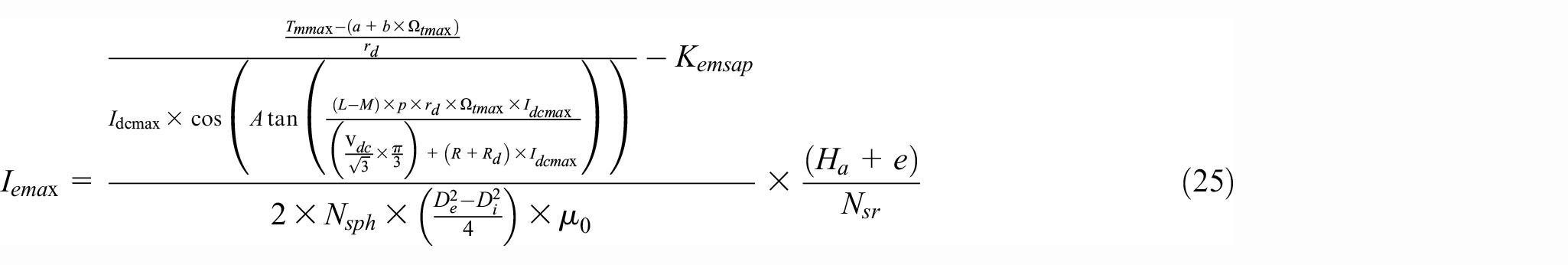
The maximal excitation current is estimated by relation (25).
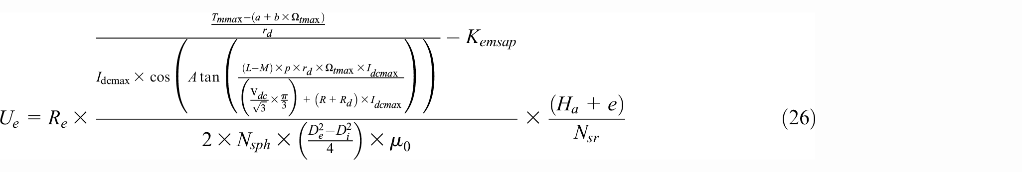
The maximal excitation voltage is estimated by relation (26).
Where Vdc and Idc are the mean values of the voltage and the output current of the rectifier, L and M are respectively the phase’s generator inductance and mutual inductance, φ is the phase shift between the phase’s currents and electromotive forces, ω is the electromotive forces pulsation and p is the generator pole pairs number.
Control model
Control technology
A two-quadrant chopper (Figure 2) is used to regulate the speed of the turbine. Indeed, a proportional-integral-derivative regulator (PID) is used to generate the reference excitation current. The modulation of the reference current by a triangular signal and a hysteresis makes it possible to generate the four control signals of this chopper. The parameters of the PID regulator are calculated iteratively by genetic method.
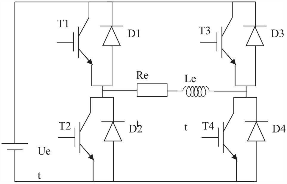
Converter structure.
The chopper operating sequences are shown in Figure 3.
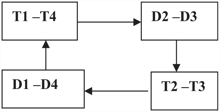
Chopper operating sequences.
When the generator speed tends to increase, the reference current modulated by a triangle signal excites the hysteresis to “1” logic (Control signal of T1 and T4) to increase the excitation current and subsequently increase the electromagnetic torque to brake the “wind turbine and contrary,” when the speed of the generator tends to decrease the reference current modulated by a triangle signal excites the hysteresis to “”0′” logic (Control signal of T2 and T3) to decrease the excitation current and subsequently decrease the electromagnetic torque.
Simulink control model
The power chain comprises the generator, the rectifier, a filter capacitor and the battery.
The Simulink model of the power chain is illustrated by Figure 4 (Belgacem et al., 2015; Ben Amor et al., 2015; Gorbel et al., 2015; Hadj Kacem et al., 2013, 2015; Marouani and Tounsi, 2014; Neji et al., 2006; Saber Hadj and Souhir, 2021; Sellami and Tounsi, 2015; Suilah et al., 2015; Tounsi, 2011; Tounsi et al., 2010; Tounsi, 2013, 2015a, 2015b).
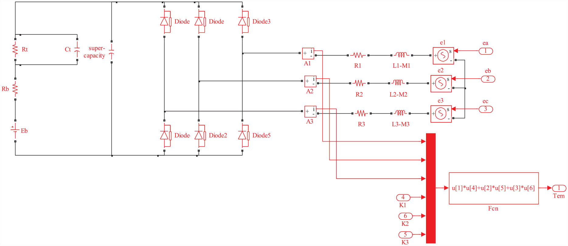
Wind turbine power system Simulink model.
The Simulink model of the electromotive forces is illustrated by Figure 5.
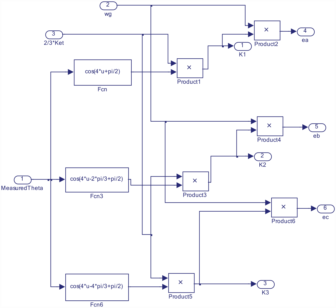
Electromotive forces Simulink model.
The regulator of the excitation current is illustrated by Figure 6. This regulator permit to generate the reference excitation current regulating the generator speed.
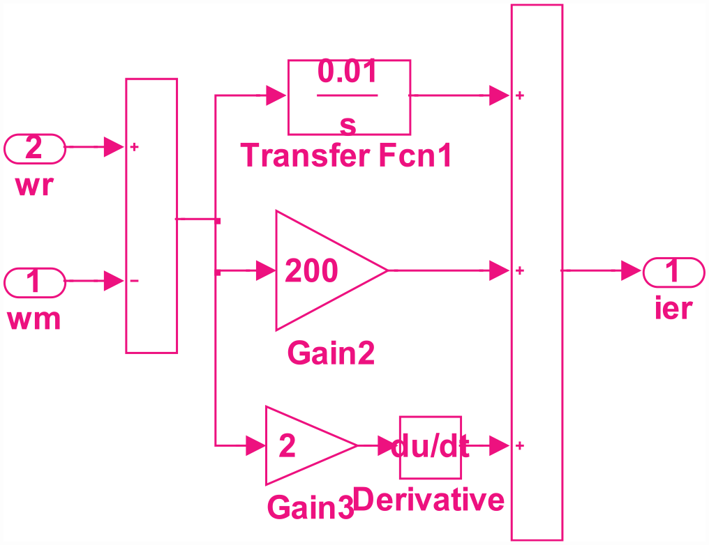
Excitation current regulator Simulink model.
The excitation current control system Simulink model is illustrated by Figure 7. This system permits to modulate and to convert the excitation reference current to the dc- dc control signal by a triangular signal and a hysteresis variant between “0” and “0” logic.

Excitation current control system Simulink model.
The global model of the power chain is illustrated by Figure 8.
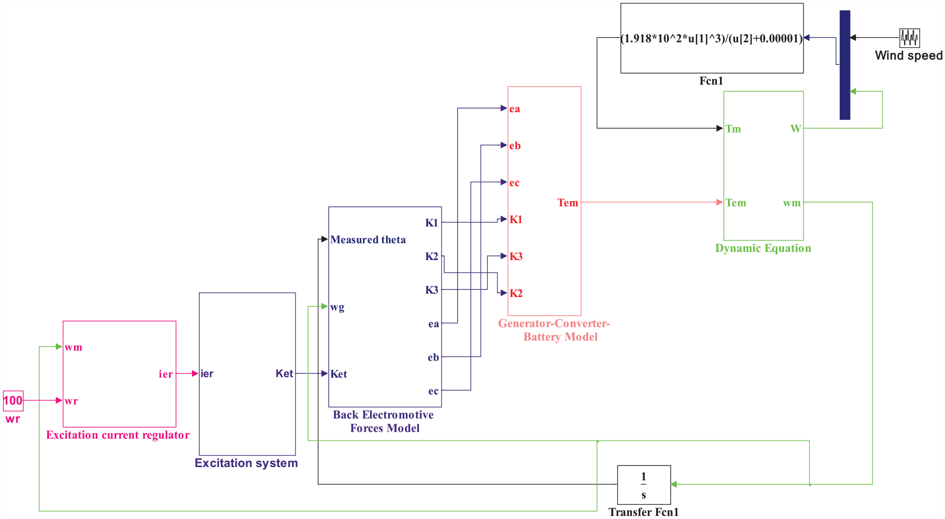
Global system Simulink model.
Simulation results
For the validation of the global study, the control model is solved by three variable step solvers to know:
ode 23s (stiff/Mod.Rsenbrock).
ode 15s (stiff/NDF).
ode 23tb (stiff/TR-BDF2).
Simulations of the power chain model for the three cases are realized according the data extracted from wind turbine analytical model as shown in Table 1.
Simulation parameters.

Figure 9 illustrates the evolution of the wind speed over time. This figure illustrates zones of over-speed and strong accelerations which present severe constraints during the operation of the turbine.
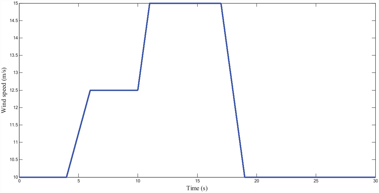
Wind speed.
Figure 10 illustrates the evolution of the electromotive forces in versus time. Figure 10 demonstrates that the magnitude of the electromotive forces is influenced by the regulated excitation current. Also Figure 10 demonstrates that the magnitude of the electromotive forces is regulated by the regulation of turbine speed to constant value.

Electromotive forces.
Figure 11 illustrates the evolution of the phase’s currents in versus time. Figure 11 demonstrates that the magnitude of the phase’s currents is influenced by the regulated excitation current. Also Figure 10 demonstrates that the magnitude of phase’s currents is regulated by the regulation of turbine speed to constant value.

Generator’s phase’s currents.
Figure 12 illustrates the evolution of the phase’s voltages in versus time. Figure 12 demonstrates that the magnitude of the phase’s voltages is influenced by the regulated excitation current.

Generator’s phase’s voltages.
The control signal (Figure 13) illustrates the principle of the used Pulse Width Modulation technique (PWM). The duty cycle of the control signal pulses at the rate of variation of the average value of the excitation current over a modulation period.

Control signal.
The excitation current (Figure 14) is regulated to impose a wind turbine resultant torque constant permitting the regulation of the generator’s speed to 50 rad/s. The excitation current increase in average value when the turbine speed tends to exceed its limit.

Excitation current.
The electromagnetic and mechanical torques of the turbine are illustrated by Figure 15. Figure 15 demonstrates that the electromagnetic torque is negative to reduce the resultant torque value at high speed. The electromagnetic torque increase when the turbine speed tends to exceed its limit.
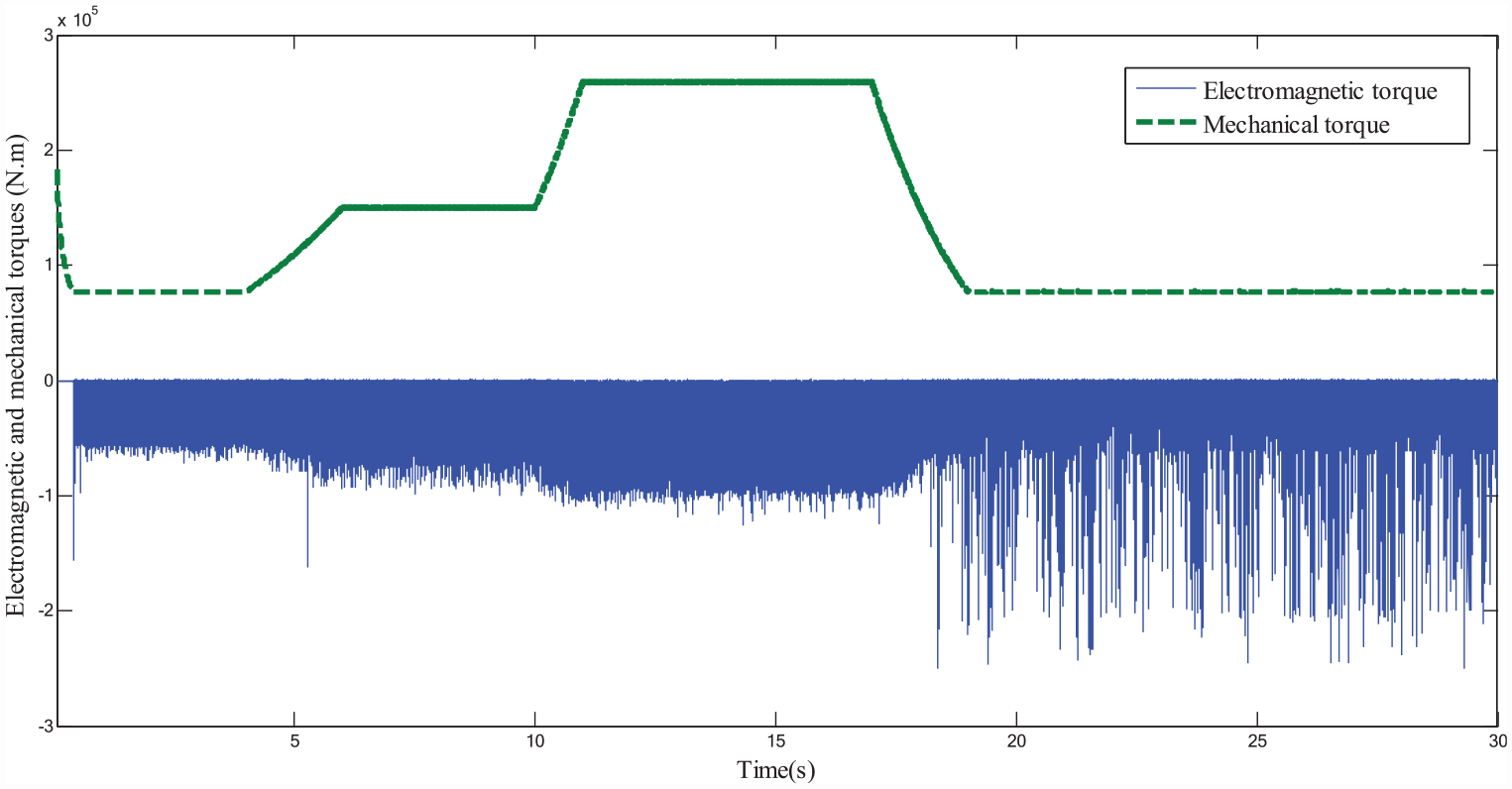
Electromagnetic torque.
Figure 16 demonstrates that the response generator angular speed accurately tracks the reference angular speed which shows the performance of the developed control technique. The regulation of the generator angular speed allows the stability of the global system at the optimal regime.

Regulated generator’s angular speed.
The batteries recharging voltage (Figure 17) is regulated according to the regulation of the generator angular speed and excitation current.

Batteries recharging voltage.
The batteries recharging current (Figure 18) is regulated according to the regulation of the generator angular speed and excitation current.
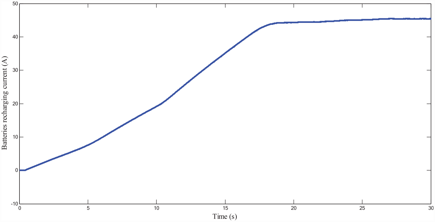
Batteries recharging current.
The turbine recovers approximately 12 × 10−3 kW.h (Figure 19) which is a significant value with regard to the used speed cycle.

Recovered energy.
The regulation of the electromagnetic torque by regulation of the excitation current permit to maintain the magnitudes of the generator’s electromotive forces, the phase’s current and voltage, the recharging current and voltage to optimal admissible values.
Conclusion
This paper presents a methodology for systemic design and control of a synchronous generator with hybrid excitation for the generation of wind energy. The design of the generator is made by the analytical method taking into account the interactions of the global system. The regulation of the speed of the turbine is ensured by adjustment of the excitation current to regulate the electromagnetic torque and in this case the excitation current is limited to a fixed value. A control model regulating the turbine speed by regulation of the excitation current for protection of the system components against wind over-speed is developed.
The simulation result validates the global study.
In conclusion the global system can industrialize for replacement of the other expensive and less robust wind turbine systems.
Footnotes
Declaration of conflicting interests
The author declared no potential conflicts of interest with respect to the research, authorship, and/or publication of this article.
Funding
The author received no financial support for the research, authorship, and/or publication of this article.