



Abstract
Wind turbine operates in harsh natural environment, and large cyclic loading will cause significant damage on the blade structure. Therefore, it is important to understand the structural behavior of this blade structure for a proper design. This paper presents an investigation of structural response of 3-KW composite blade for H-type vertical axis wind turbine (VAWT). The blade is modeled and simulated by using SOLIDWORKS Simulation 2020 software. FEA (Finite element analyses) are conducted to investigate the stress analysis (stress and displacement) and modal characteristics (natural frequency and associated mode shapes) of blade structure. The blade design takes into account of three constraints: stress, displacement, and vibration. The results show that the maximum stress is 39.17% lower than the allowable stress, the maximum displacement is 95.1% lower than the allowable deformation, and the first mode frequency of the blade is 67.8% higher than the allowable tolerance. These results demonstrate that the blade structure meets the static design requirement, remaining unaffected by resonance phenomena, and moves in a stable way during the different phases of the wind turbine operation.
Introduction
The necessity of reducing fossil fuel dependency has become priority issue a significant global concern. To attain this goal, there has been a remarkable acceleration in development and utilization of renewable energy sources. Among all these energies, wind energy sector has seen a dramatic expansion in the last decade, and it continues to advance at a high growth rate (Lagdani et al., 2021; Roummani et al., 2018; Saihi et al., 2019). In 2022, an estimated 94 GW of new wind power capacity was installed in worldwide (GWEC, 2022).
Depending upon the rotation axis of rotors, wind turbines are classified into horizontal-axis wind turbine (HAWT) and vertical-axis wind turbine (VAWT). Compared with HAWTs, VAWTs have received interest due to their simpler geometry, lower required material, and lower manufacturing and maintenance costs (Deng et al., 2020; Khelifi et al., 2017). As global energy demand is increasing, the utilization of domestic VAWTs, particularly Darrieus (H-type) turbines, are most appealing for energy supply, particularly in cites and semi-urban areas (Ferroudji, 2021; Ghasemian et al., 2017; Jafari et al., 2018).
Throughout the wind turbine development, blade is generally regarded as the most critical component of whole system. The turbine’s efficiency primarily depends on both aerodynamic profile and the blade materials (Bora et al., 2023). The blade structure sustains different kinds of loads during both operation and parking states. These loads, particularly the aerodynamic loading, greatly impacts the fatigue lives of the structures. Therefore, investigating the structural response, including stress and vibration responses, and fatigue characteristics of the blade during the design process is necessary to improve their mechanical performance and increase the lifetime (Zhu et al., 2016).
In terms of the structure, blades are now constructed of composite materials. Composite materials (generally glass-fiber/epoxy) are well suitable for complex design constraints, like being lower weight and as rigid as possible. Therefore, these structures, are slender and elastic in construction, are highly susceptible to vibrations. When designing the blade structure, it is therefore crucial to consider its dynamics with special emphasis on resonance (excitation frequency). A modal (or frequency) analysis, which is the first step for the dynamic analysis, was performed to understand the essential dynamic characteristics of the blade structure, including natural frequencies and mode shapes. Knowing these natural frequencies is crucial to preventing resonance ensure the prevention of blade resonance region under wind loads and undesired structural elastic mechanisms in the blade (Boudounit et al., 2021; Wang et al., 2016; Wilson, 2002).
Based on the literature (Bel Laveda et al., 2023; Ferroudji et al., 2021; He et al., 2020; Khelifi et al., 2014; Nezzar et al., 2022), it is recommended to use a 3D (three-dimensional) model for the numerical study, and both FEA (finite element analysis) and CFD (computational fluid dynamics) techniques. Currently, FEA is regarded as an efficient and indispensable tool for studying structural integrity assessment of VAWT structures.
Herein, a whole blade model of H-type VAWT (3-KW) is established and a FEA of the stress analysis (stress and displacement) and modal characteristics (natural frequency and mode shapes) of blade structure, under normal-operating load conditions (IEC 61400-2 standard), is investigated. The parameters of the blade model and FEA modeling are described in Section 2. Stresses, displacements, and modal responses are investigated in Section 3. Finally, the conclusions are summarized in Section 4.
Methodology
In this section, the stress and modal analyses of the blade structure using FEA involve creating a detailed 3D model of the blade, material properties, applying loads and boundary conditions, generating mesh, and conducting stress and modal simulations to evaluate its structural behavior and stability at operating speeds.
Blade geometry
The straight blade model selected for the current study is adopted from H-type VAWT (3-KW). Each component of the blade structure is modeled (3D) independently and assembled a CAD environment, SOLIDWORKS commercial software (version 2020). The geometry is defined by three sub-structures (bonded together) is used to design the blade. The blade has a constant NACA 0018 airfoil profile along its span. The blade has a length of
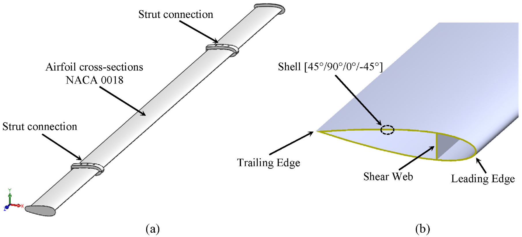
(a) Entire blade model and (b) cross-sectional view.
FEA modeling
Material
Choice of blade material is the crucial property function in the reliability and efficiency of the blade design. In former times, various materials were selected for manufacture blade structure such as aluminum and composites materials (Wang et al., 2016). Due to they are inferior fatigue performance and blade mass concerns, metallic materials have to be avoided (Hand et al., 2021). Opposite of that, composite materials (such as glass and carbon epoxy) have a good fatigue performance and excellent stiffness/mass and strength/mass ratios. In this current study, aluminum material is chosen for the two strut connection pieces, while glass/epoxy layers are used for the rest of the blade structure, as referenced in (Dabachi et al., 2022). Table 1 tabulates the mechanical properties of the both materials. The configuration of glass/epoxy layers [45°/90°/0°/−45°] with varying thickness of each layer (45°:0.312 mm, 90°:1.872 mm, 0°:0.468 mm, and −45°:0.348 mm) is applied to our blade model and recommended by (Ferroudji et al., 2023). Total sum of all the layer thicknesses is 3 mm which is the total shell thickness of the blade. Material properties, are tabulated in Table 1, are entered as input to the SOLIDWORKS Simulation.
Mechanical properties of the materials used (Hameed et al., 2015).

Loadings
IEC61400-2 design standards (International Electro-technical Commission (IEC), IEC 61400-2, 2006) requires the inclusion of should encompass the start-up, normal-operation, shut-down, and parked conditions in dynamic-response analysis for small wind turbines. In this present study, the only normal-operation condition was addressed because it contributes for over 99% of the total fatigue damage (Zheng et al., 2022). For our wind turbine, the normal operation condition corresponds to a mean wind speed interval of 3–19 m/s (Nezzar et al., 2022).
During wind turbine operation, blade structure is subjected to various loading scenarios such as its own gravity, aerodynamic, centrifugal, seismic loads, and inertial forces (Hameed and Afaq, 2013). In this study, the aerodynamic (lift,


Where
Boundary conditions
FE model of blade must eventually integrate all structural properties and boundary conditions are set in a way similar to the in-field operational conditions of the given blade structure. The boundary conditions consisted of fixing all 6 degrees of freedom of nodes, Encastre type, that are placed at the strut connections, which are at the distance of 0.99 m (0.206H) and 3.81 m. The total uniformly load (aerodynamic + centrifugal forces) is applied, at the same time, to along the outward surface of the blade. Figure 2(a) shows the boundary conditions and loadings applied to the blade model, where the purple arrows are for total loads (aerodynamic + centrifugal) and the red ones for gravitational load.

(a) Boundary conditions and (b) FEM mesh.
Mesh generation
In the meshing process, we have employed two types of mesh for the blade model, the solid elements type (tetrahedral) and shell elements type, Figure 2(b) presents the blade model with the mesh used. The solid elements type, with 10 nodes, was used for two strut connections of the blade and whereas the shell element type was selected for the rest of the blade. The blade model is constructed and automatically meshed. The total model consisted of 135,535 nodes, 76,146 elements, and 514,896 degree of freedom (DoF).
Results and discussion
This section represents the simulation results, stress analysis (stresses and displacements) and modal analysis (natural frequencies and corresponding mode shapes), obtained from FE simulations.
Stress analysis
For the stress analysis, we applied aerodynamic, centrifugal, and gravitational loads on the blade model to evaluate the stresses (von-Misses) and displacements. Figures 3 and 4 present the simulation results for the resulting von Mises stress and displacement distributions, respectively. Table 2 summaries the outcomes of the results of this analysis.

Maximum stresses: (a) 10 m/s case and (b) 19 m/s case.
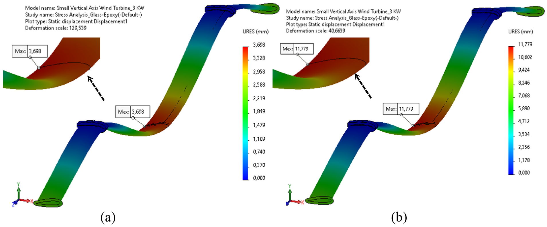
Maximum displacements: (a) 10 m/s case and (b) 19 m/s case.
Stress analysis results for blade model.

As can be seen from Figure 3(a) and (b), the maximum blade stress concentrations occur at strut connection for both cases. Their values are 76.33 MPa (10 m/s case) and 200.72 MPa (19 m/s case). These maximum values have been compared with the material yield limit value, 330 MPa, obtaining a safety margin [equation (3)], of 76.87% and 39.17%, respectively.

As can be seen from Figure 4(a) and (b), for both cases, the regions of maximum displacement occur at middle region of the blade. Their values are 4.323 mm (10 m/s case) and 11.78 mm (19 m/s case).
The maximum displacement (

According to (Tian et al., 2021), the dallow is set to 5% of the total blade length (
Modal analysis
Blade’s structure, as all engineering structures, should be designed by considering its dynamics with special emphasis on resonance, as this can have influence structural performance and fatigue strength. A modal (or frequency) analysis, which is the first step for the dynamic analysis, was performed to understand the essential dynamic characteristics of the blade structure, including natural frequencies and mode shapes. Knowing these natural frequencies is crucial to preventing resonance ensure the prevention of blade resonance region under wind loads and undesired structural elastic mechanisms in the blade (Boudounit et al., 2021; Wilson, 2002).
The modal analysis was done on the blade model using the same boundary conditions (at their strut connections) and the blade is free vibration and non-rotating (no loads on the blade). In the end, natural frequencies and corresponding mode shapes of the blade model were obtained.
For solving dynamic problems, mass participation ratios are crucial in determining the number of adequacy modes to be calculated. Numerous FEA codes require that at least 80% of the masse of the structure should participate in each principal direction (Ferroudji et al., 2018). In this study, it would necessitate the calculation of 600 modes to achieve the 80% mass participation in each direction.
The first fourth blade modal shapes are depicted in Figure 5, the un-deformed model is also displayed to facilitate the illustration. The results show that the third first vibration modes reproduce bending of the blade along X-direction. The fourth vibration mode reproduces a second bending of the blade along X-direction in ZY plane. The first five sorted natural frequencies for blade structure are located in the frequency range between 23.442 and 97.426 Hz and are tabulated in Table 3.
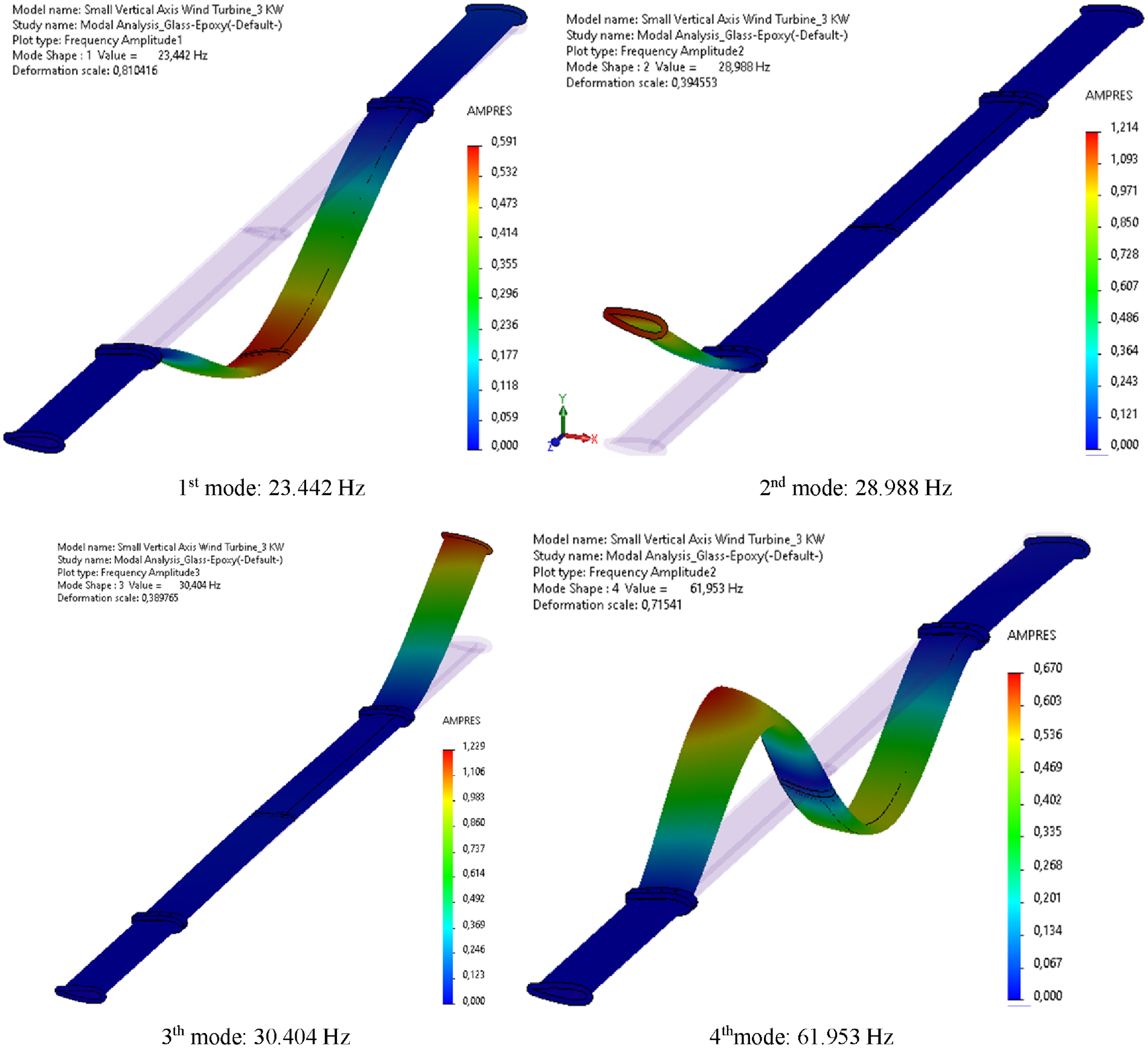
Natural mode shapes of the blade model.
Frequencies of the first five orders.

To avoid the resonance problems, the natural frequency of the blade structure (

where

Where
The maximum rotor rotational speed of the VAWT studied is

The vibration modes with the lowest frequencies, specifically first and second vibration mode, represent the most prominent in terms of structural vibrations. The first mode frequency of the blade structure is 23.442 Hz (Table 3), which is 67.8% higher than the allowable tolerance value of 13.97 Hz. This indicates the effect of resonance does not occur during wind turbine operation (0–19 m/s).
Conclusion
This study investigates the stress, displacement, and modal characteristics of a composite blade for a 3-kW small scale VAWT under normal-operating load conditions (IEC61400-2 standard). The structural analysis was performed to evaluate the proposed blade model using SOLIDWORKS FEA. The obtained results were divided into two parts; the first one deals the structural stress analysis of the blade and the second part concerns with the structural modal analysis.
For the stress analysis, the results show that the current blade structure meets the design requirement and it will able to resist the operation loadings, with allowable stress of the blade material (with a safety margin of 39.17%) and the maximum displacement is 95.1% lower than the allowable deformation. For the modal analysis, the results show that the first mode frequency of the blade structure is 67.8% higher than the allowable tolerance. These results indicate that the blade is unaffected by resonance phenomena and that moves in a stable way during the different phases of the wind turbine operation (0–19 m/s).
Footnotes
Declaration of conflicting interests
The author(s) declared no potential conflicts of interest with respect to the research, authorship, and/or publication of this article.
Funding
The author(s) received no financial support for the research, authorship, and/or publication of this article.