




Abstract
To increase power generation, the next generation wind turbines are focusing more on hybrid systems. There is always a demanding need for more efficient wind power generation systems. In view of the improvements in the known types of turbines now available in the prior art, the present work proposes a novel hybrid wind and solar turbine construction wherein the same can be utilized for generating additional electrical power. A practical and feasible combination of wind turbine and solar panels has been designed. In this proposed novel arrangement, solar panels are secured to the surface of nacelle heli-hoist to supplement the power generation of a wind turbine.
Introduction
The demand for renewable energy has been increasing day by day. Out of many available renewable resources the most practical options are solar energy and wind energy. As per Proof of Betz Law (1919), wind turbines provide a theoretical efficiency of 59.3%, but their average practical efficiency ranges from 35% to 40%. Solar panels provide a practical efficiency of 9%–12%. Wind turbines makes use of high potential winds and convert wind energy to electrical energy. Wind turbine construction (as shown in Figure 1) includes tower, nacelle, rotor and blades. For offshore wind turbines heli-hoist will be added on top of the nacelle.
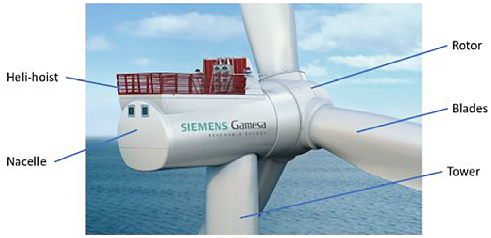
Construction of wind turbine.
Heli-hoist railings provide safety for the service personnel working on top of the nacelle. When there is a need for inspection, service personnel must travel to the wind turbine (which is installed far inside Sea) and making usage of sea transport sometimes can create delays and transportation issues. In these scenarios, service personnel generally make use of helicopter and lands on the heli-hoist system (as shown in Figure 2). After landing, service personnel go inside nacelle/tower by opening the hatch and thereby perform the required operations.

Service personnel landing with the help of helicopter.
Combined use of solar panel and wind turbines have been in discussion since few decades. Hybrid Systems can always generate additional power compared to the traditional systems.
Ottman (2012), Malcolm (2012), Kashyap (2006), Armstrong (2017), Akpan et al (2022) and Varshini et al (2021), the hybrid systems developed so far primarily concentrate on installing solar panels on wind turbine towers and blades. However, the cylindrical shape of the towers and the intricate aerodynamic designs of the blades make these concepts nearly impractical to implement. These proposed designs can also lead to friction losses in wind turbines caused by bearings and magnetic levitation, Kamble and Tale (2022). Researchers like Pristash (2017), Kimberg (2015) and Eltayeb et al. (2023) have broadened their study to examine the effects of orientation and tilt angles on solar panels in hybrid systems, utilizing servo motors for this analysis.
Christy et al (2013) and Zaman (2015), some studies have even explored the application of hybrid solar and wind systems in conical tree designs and portable rechargeable batteries. Zheng et al (2021) have created a floating cage that features wind turbines mounted at each end and solar panels installed on the central deck, resulting in a hybrid design.
In contrast to the existing literature, this work presents a simple and practical solution for mounting solar panels on wind turbines. It proposes a novel arrangement for installing solar panels on the nacelle heli-hoist railings, which has been designed as part of this study.
Methodology
For this work, an offshore wind turbine nacelle with heli-hoist railings has been considered.
Heli-hoist railings are basically safety fences which are surrounded on top of the nacelle to provide safe access for the service personnel. These railings are vertical and are mounted to the nacelle top cover/nacelle structure.
Heli-hoist railings are generally classified into two categories:
(a) Heli-hoist railing with safety fences, as shown in Figure 3.
(b) Heli-hoist railing without safety fences, as shown in Figure 4.
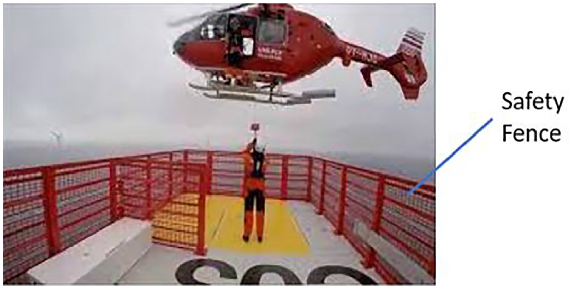
Heli-hoist railings with safety fence.

Heli-hoist railings without safety fence.
Generally, choice of safety fence addition is dependent on-site conditions and on customer demand.
To simplify the loading and interface constraints, heli-hoist nacelle without safety fences has been considered for this work (as shown in Figure 5).
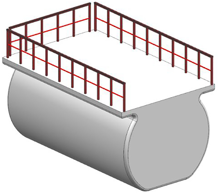
Nacelle with heli-hoist design considered for this work.
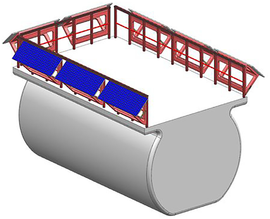
After many design iterations for mounting supports, the below shown two configurations have been proposed (as shown in Figures 6–10).
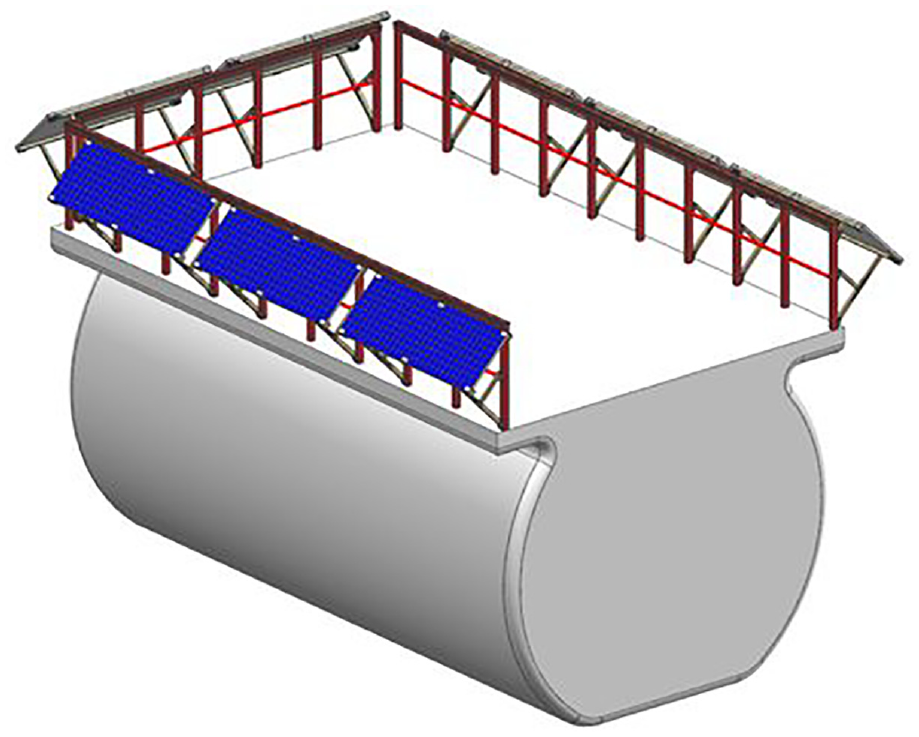
Design configuration 1 with adjustable supports.
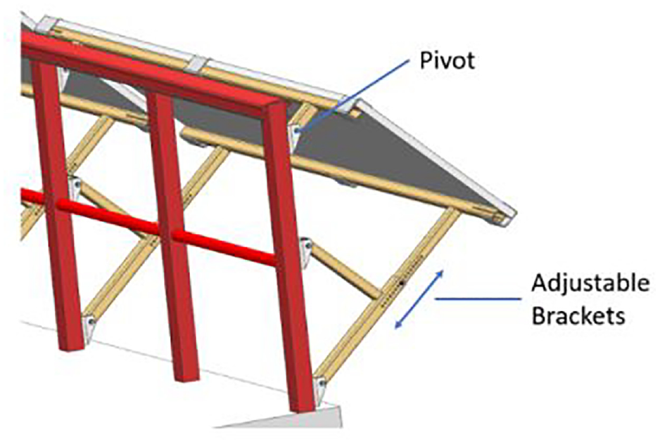
Detail view of design configuration 1 with adjustable supports.
Design configuration 2 with rigid machined supports.
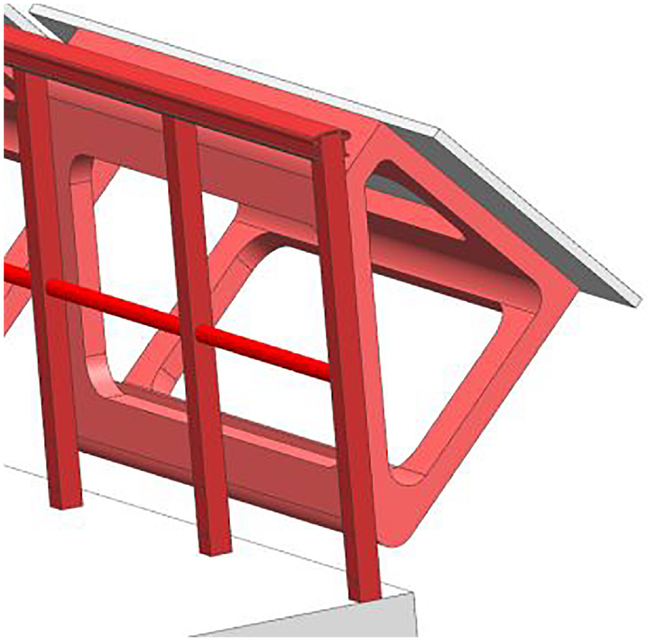
Detail view of design configuration 2 with rigid machined supports.

Top view showing the overall arrangement of proposed design.
Design configuration 1 proposes an adjustable solution. In this design, the top bracket is mounted on a pivot support which provides rotation flexibility about pivot point and the bottom bracket is mounted on a length adjustable beam. In contrast design configuration 2 proposes a fixed and machined block on which the solar panel gets mounted.
Design loads and acceptance criteria’s
The proposed design is mounted outside the nacelle and thus exposed to all harsh environmental conditions. The major loads acting on the system are:
wind loads; and
self-weight of the panel
The structural integrity of the design with respect to material stress limits governs the acceptance criteria of the design.
Wind loads versus wind speed
Wind loads exert a great amount of Load on the design. The loads acted by the speed proportionally increases with the speed of wind. When wind is stopped by a surface, the dynamic energy of the wind is converted into pressure. The pressure acting on the stopping surface converts into force.


Where:
Fw = wind force (N);
Pd = dynamic pressure of the wind (Pa);
ρ = density of air (kg/m3) = 1.229 kg/m3; and
v = wind speed (m/s).
To consider the worst-case governing load scenarios we have taken typhoon wind conditions. Typhoon wind speed considered for the calculation is 57 m/s (reference from GE Wind Turbine [n.d.] design).
A = Surface Area (m2). Surface area obstructing the wind to create pressure equals to the surface area of the solar panel. A = 10 m2 (as per the proposed design);
Fw = (1/2) × 1.229 × 572 × 10 (replacing all values in equation (2)); and
Fw = 19,965 N.
Self weight
The average weight for 5 feet by 4 feet solar panel is around 40 pounds (18 kgs). In this work solar panel of 10 feet by 4 feet has been considered which gives the weight of panel as 36 kgs. Converting this weight into Force acting at COG:

Fs = 36 × 9.8 = 353 N.
Total force
Total force acting on the design, Fd = (Fw + Fs) × FOS;
Factor of safety, FOS = 1.5 (considering conservative scenarios); and
Fd = (19,965 + 353) × 1.5 = 30,477 N.
Acceptance criteria
Structural steel grades like S235 and S355 are generally preferred for European markets due to abundant availability and easy procurement. S355 is chosen for higher load applications, whereas S235 is chosen for lower load applications.
S355J0 is designed for mechanical impact properties at 0°C, S355JR is designed for mechanical impact properties at room temperatures and S355J2 is designed for mechanical impact properties at -20°C. Since the proposed design is exposed to outside air and temperatures will drop to negative ranges. Hence S355J2 is chosen as the material grade and the design stress should be less than that of allowable yield stress of 355 MPa.
Results and discussions
Since this design deals with mounting supports, static structural calculation has been performed to check the stress limits. Finite element software NX Nastran has been used to validate the design.
Fine meshing takes lot of time to solve but provides close to accurate results, whereas coarse mesh takes very less time to solve but deviates from accuracy. Hence an optimal ratio of meshing needs to be considered. In this work, 3D tetrahedral CTETRA (10) element has been chosen as the mesh type and mesh ratio of 0.7 (close to fine mesh) has been applied (as shown in Figures 11 and 12).
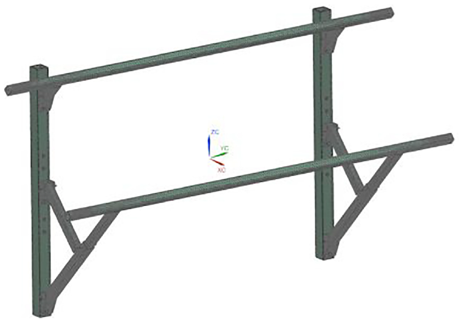
Meshing of design configuration 1.

Meshing of design configuration 2.
Boundary conditions and design force (calculated in Section ‘Total force’) have been applied on the designs and are shown in Figures 13 and 14.
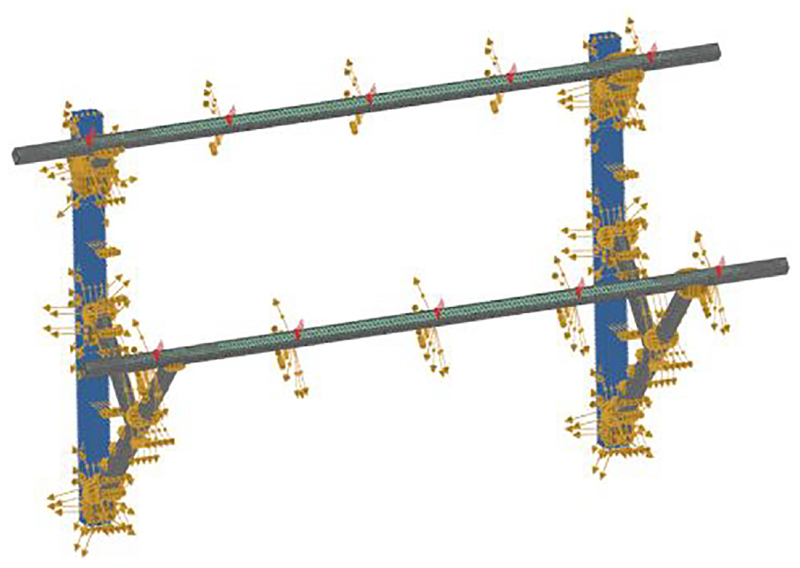
Boundary conditions and forces on design configuration 1.
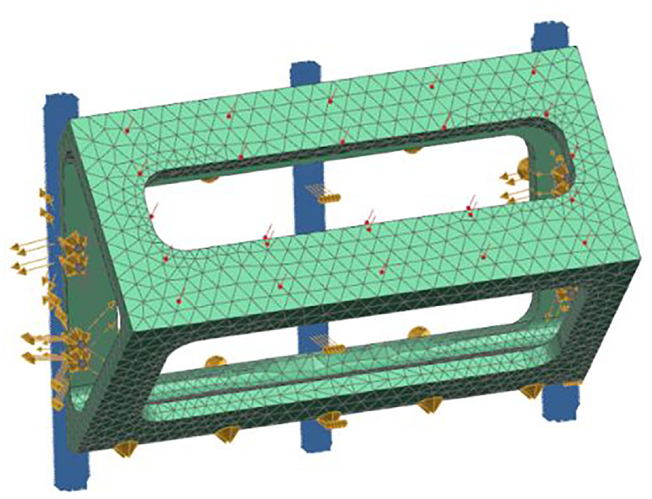
Boundary conditions and forces on design configuration 2.
The analysis run has been solved without any convergence errors and Von-mises stress has been obtained as shown in Figures 15 and 16.
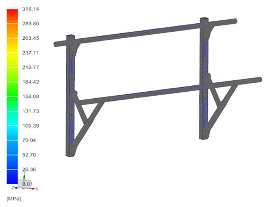
Von-mises stress plots for design configuration 1.
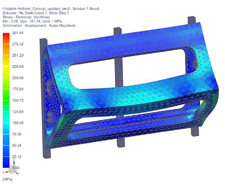
Von-mises stress plots for design configuration 2.
Considering the anisotropic nature of material, a safety factor of 1.1 has been induced on the yield strength. This reduces the yield limit to 323 MPa.
From Figures 15 to 16 the design induced stresses are 316 and 301 MPa and these are less than the allowed yield limit of 323 MPa.
Conclusion
In this work, a novel design for mounting solar panels on wind turbines has been proposed and validated.
The below deductions are made from this research work:
The proposed area of mounting is accessible and feasible.
Two design configurations have been proposed and they are within the design limits of acceptance criteria’s and are ready to be manufactured.
Design configuration 1 can be clubbed with servo motors/sensors and actuating cylinders to adjust the angles of solar panel with respect to the sun’s orientation
Design configuration 2 can be checked with cast iron material. Casted components provide huge cost reductions when manufactured in big numbers.
The additional power generated with the help of these solar panels can be used for auxiliary power requirements like initial torque required for starting wind turbine, or powering cooling pump.
Footnotes
Acknowledgements
The completion of this research work would not have been possible without the support from Siemens Gamesa Renewable Energy A/S. We would like to extend our sincere thanks to all the participants in our study, who generously shared their time, experiences, and insights with us. Their willingness to engage with our research was essential to the success of this work, and we are deeply grateful for their participation.
Declaration of conflicting interests
The author(s) declared no potential conflicts of interest with respect to the research, authorship, and/or publication of this article.
Funding
The author(s) received no financial support for the research, authorship, and/or publication of this article.
