
Abstract
The rising global energy demand and environmental impact of fossil fuels intensify the search for efficient renewable solutions. Small-scale vertical-axis wind turbines (VAWTs) in constrained environments (e.g., highway dividers) offer potential but face inefficiencies with conventional generators at low wind speeds. To address this, a low-rpm Permanent Magnet Synchronous Generator (PMSG) is proposed for operation at 50–900 rpm, aligning with the operational speed range of the VAWT in this study. A 4-pole, 24-slot configuration generator has been designed in ANSYS Maxwell to enhance induced voltage while minimizing cogging torque. Results demonstrate that the proposed generator outperforms conventional dynamos such as brushed DC generators and existing PMSGs in both voltage and current output. Simulations confirm a voltage output of 89.57 V and current of 3.98 A at 250 rpm, outperforming conventional brushed DC generators (conventional dynamos) by 300% in terms of voltage output. The generator operates without external excitation, ensuring higher efficiency and reliability in low-torque applications. This work offers a viable solution for decentralized wind energy generation.
Keywords
Introduction
This is the period of decentralized energy production, utilizing small, autonomous wind turbines. The ratings of the wind turbines often reach up to 10 kW as discussed by Möllerström et al. (2019). According to Ahmed and Cameron (2014), due to the compact design, small wind turbines can be mounted on the rooftops of residences located in coastal regions and serve as effective options to address the ongoing energy issue. Small wind turbines predominantly utilize permanent magnet synchronous generator (PMSG). High power density and current density have led to the replacement of the excitation system in electrical generators with robust Neodymium Iron Boron (NdFeB) permanent magnets (PMs). PMSGs are suitable for low and variable shaft speed applications (Aleksashkin and Mikkola, 2008). The characteristics of low and variable shaft speed have enabled the direct coupling of the electrical generator with the shaft of a wind turbine. The system is characterized as a direct-driven wind turbine system (Susanto et al., 2019). Kumar et al. (2020) highlighted that numerous alternative machineries may also be utilized in wind turbines. These encompass axial flux machines, transverse flux machines, and hybrid excited machines.
In recent years, the prevalence of hybrid excited machines has significantly increased. These devices, equipped with supplementary excitation sources, can effectively function as generators in horizontal-axis low-speed wind turbines. The primary benefit of these machines is their capacity to produce voltage at extremely low or significantly fluctuating speeds. Their drawbacks include the intricate design and raised cost, which serve as significant disadvantages for small vertical-axis turbines. These constructions can be categorized into various types: those with a split electromagnetic circuit, those with a combined electromagnetic circuit, and machines using a claw-pole topology (Wardach et al., 2020).
With doubling length, axial length adjustments were shown to increase voltage by a factor of 2.25. Sitheswaran et al. (2021) proposed a double-sided coreless axial flux permanent magnet generator (AFPMG) to overcome the limitations of traditional radial flux PM generators (RFPMG) at low-speed wind energy conversion in India, where average wind speeds were around 6 m/s. AFPMG showed superior performance across several parameters, including flux density, induced EMF, cogging torque, efficiency, decreased material consumption and losses using finite element analysis (FEM) with ANSYS Maxwell. The design of a coreless PMAFG for low-speed wind turbine application was presented by Yusuf et al. (2018). The generator’s double rotor single stator configuration (12 slots, 8 poles) with NdFeB magnets, was analyzed by FEM using Infolytica MagNet software. The PMAFG was able to achieve 12.8 V and 45 A at 350 rpm under varying loads (10–100 Ω). Another design of a low-speed PM generator for small wind power plants using NdFeB magnets was presented by (Irfan et al., 2018).
Using FEM software, the generator was modeled with an 18 cm diameter, 8 magnetic poles, and 12 stator units, each containing 55 coils. With a 0.5 mm air gap, it produced an average output voltage of 185.44 V and a current of 5 A at 500 rpm. Pramurti and Hutajulu (2018) reported the design and optimization of a dual-stator radial flux PM generator (DS-RFPMG) aimed at reducing cogging torque in low-speed wind turbines. Three methods were evaluated: stator teeth pairing, stator displacement, and pole arc ratio. With the optimal configuration ([6.5–11.5 teeth pairing; ±40° displacement; 0.6667 pole arc]), cogging torque was reduced by 83% (to 0.21 Nm), frequency harmonics were reduced by 59%, and output power increased to 2004 W, representing a 66% improvement. Kostro et al. (2017) developed a low-speed PMSG with additional transverse windings for micro hydroelectric and small wind power plants. The study used FEM to optimize parameters like air gap size, rotor geometry, and magnetic flux to increase efficiency. Results indicated that the addition of transverse windings significantly increased efficiency, increasing power output while reducing required rotational speed and electromagnetic torque.
A crucial component of wind power stations is the power generator, a device that transforms wind turbine energy into electrical energy. The problem stems from the prevalence of high-speed induction generators in the market, which demand a speed range of 1000 rpm to 1500 rpm and requires initial electrical energy to establish a magnetic field (Bensalah et al., 2022; Boldea, 2017). The turbines, equipped with a generator, require low rotational speed and no initial electrical input, due to the average wind speeds of 3.47 m/s in Indonesia and 2.7 m/s (Apatya et al., 2017; Duma et al., 2010). Wind speed is variable; in some areas, it is consistently lower than in coastal regions this low wind speeds hinder the operation of high-speed generators. The implementation of a wind power station has been successfully executed in the southern coastal district of Malang. Nevertheless, the prototype continues to utilize a modified automotive generator (dynamo), resulting in constrained voltage and current output. Asy and Ardiyatmoko (2020) investigated a low-speed electric generator was investigated; however, the issue with this generator was that its low speed is 200 rpm, resulting in low induced voltage and current.
The design and optimization of a low-speed radial flux PM generator for wind turbine applications was presented by Sathasivam et al. (2023). By adjusting the stator teeth width, the power output was improved, and pulsating torque was reduced, resulting in up to a 3.95% increase in voltage and a 3.4% improvement in power. The simulation was carried out in Finite Element Method Magnetics (FEMM) using detailed parameters, including a wind speed of 5 m/s and a rotor speed of 300 rpm. A low-speed PMSG was designed for vertical-axis wind turbines, and radial and tangential magnet arrangements were compared by Cichowicz et al. (2023). FEM were performed, and the results were compared with experimental data to show that radially magnetized designs produce greater torque (326.64 Nm vs 242.44 Nm) and higher efficiency (96.9%) than tangential designs. The reuse of small electrical machines, such as automobile alternators and induction motors, for low-cost variable-speed wind turbines was investigated (Ballestín-Bernad et al., 2022). Different PM arrangements were analyzed using 2D-FEM simulations with FluxMotor software, and the performance of different designs was similar. It was concluded that the V-block PM configuration achieved comparable efficiency (up to 96.9%) with reduced cogging torque.
Six design alternatives of a PMSG for low-speed wind turbines were investigated by Agrebi et al. (2021) considering both surface-mounted and interior magnet configurations. The study optimized stator dimensions, winding configurations, and axial lengths using FEM with ANSYS and Motor-CAD, achieving peak air-gap flux densities of 1.315 T for the surface-mounted design and 1.10 T for the interior magnet design.
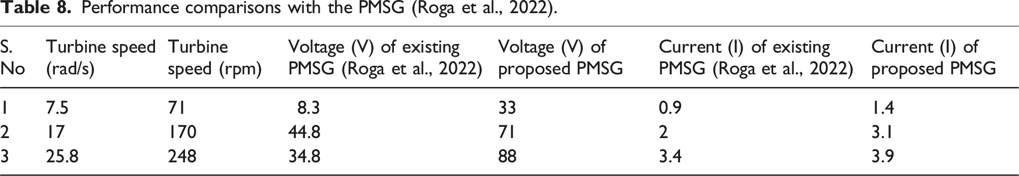
The power output from a singular wind energy facility is inadequate for continuous power generating. As a result, these energies are seasonal; for instance, wind intensity diminishes during the day. Thus, the integration and optimization of dual-stage wind turbine systems, each equipped with dedicated low-rpm PMSG, can significantly enhance overall system efficiency and reliability. By connecting both generator outputs through synchronized DC-DC conversion and regulation stages, the system maintains consistent voltage control and enables energy buffering via storage or grid integration. This facilitates the stable delivery of grid-quality power to downstream electrical loads over a 24-h period, even under fluctuating wind conditions. The proposed system is designed to improve efficiency, promote environmental sustainability, offer operational flexibility, and ensure long-term reliability. The suggested system will save maintenance expenses and harness solar and wind energy, which is abundantly available both during the day and at night. Small wind turbines, owing to the low wind velocity at an elevation of approximately 5 m, exhibit various designs, predominantly including a horizontal axis of rotation (Rosato et al., 2024). PMSG-based vertical-axis wind systems presented by Roga et al. (2022) can effectively employ Maximum Power Point Tracking (MPPT) through PI-controlled pulse-width modulation. The paper links electrical outputs (voltage, current) to mechanical performance (torque, power coefficient). Its simulation offers a transferable methodology for renewable energy system optimization.
In this paper, a low rpm generator is designed for a two-stage wind turbine, addressing the limitations of high-speed generators in low-speed environments such as highway dividers. To meet the requirements of low-speed, low-torque applications, this paper presents a novel PMSG optimized for operation within the 50–900 rpm range. The generator uses a 4-pole, 24-slot configuration with paired coils, which enhances compactness and efficiency. It demonstrates the ability to produce nearly 345 W at 250 rpm. The results are compared with those in Roga et al. (2022), where a vertical-axis wind turbine (VAWT) system using a PMSG has been analyzed through computational methods. To validate and refine the design, detailed simulations are carried out. Although the generator is not fabricated, the simulation results indicate strong potential for efficient energy harvesting from low-speed wind sources, contributing to enhanced performance, reliability, and cost-effectiveness in wind and water turbine systems.
Two-stage wind turbine
Wind energy is regarded as one of the most attractive substitutes for fossil fuels. It can also be generated by moving vehicles and captured using wind energy converters (Devashish et al., 2016; Kumar et al., 2016). Multistage turbines represent a contemporary method that is increasingly gaining traction. A turbine positioned at the center of the road can harness wind energy from both sides of the traffic, as illustrated in Figure 1, unlike a roadside turbine, which collects energy from only one side. Multi-stage Savonius turbines have been developed to improve their efficiency. Puspitasari and Sahim (2019); Meziane et al. (2020); Imran et al. (2022) proposed a hybridization of H-Darrieus and helical Savonius turbines was presented to enhance the efficiency of a basic multistage (VAWT). This configuration employed numerous rotors of one or more varieties of VAWT. In this configuration the wind flow changes depending on the vehicle’s size and speed. The Savonius rotor placed at the bottom of the turbine captures low level turbulent wind from smaller vehicles like cars. The H-Darrieus rotor positioned above it catches higher and steadier wind from larger vehicles such as buses and trucks. This two-stage setup uses wind from different heights allowing the turbine to make the most of the airflow created by mixed traffic in both city and highway conditions. Turbine installed on a highway and its common types (Aleksashkin and Mikkola, 2008).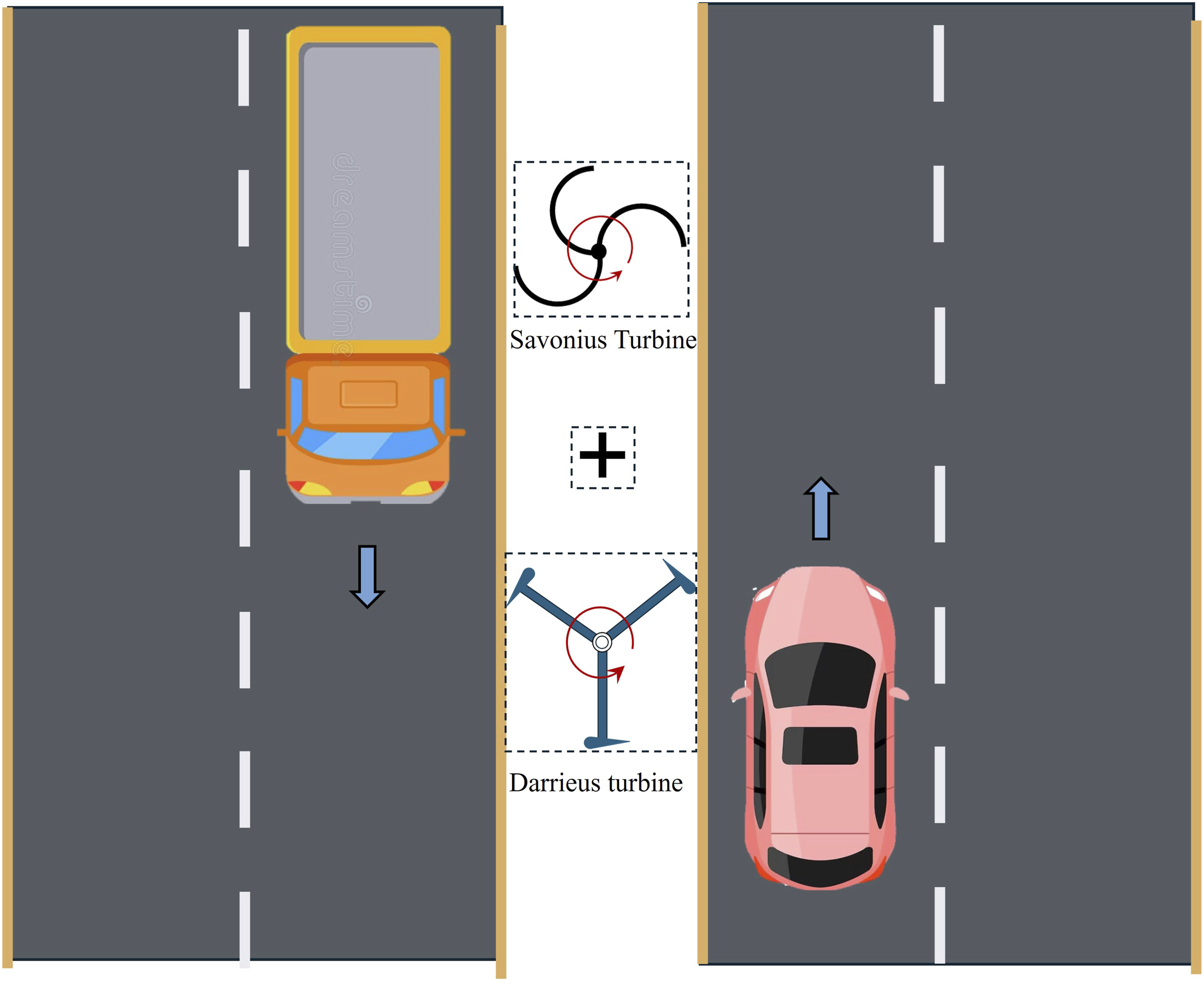
The helical Savonius turbine is a drag-type turbine, functioning analogously to the basic Savonius turbine, as presented in Figure 2. The turbine’s blades possess a concave side oriented towards the wind and a convex side directed away from it. The wind produced by driving vehicles strikes the concave side, compelling the blades to rotate around the center shaft. On the convex side, the wind is laterally deflected due to its contour. The drag force on the concave side exceeds that on the convex side, resulting in the turbine’s rotation due to this disparity in drag force. Three-blade Savonius turbine (Susanto et al., 2019).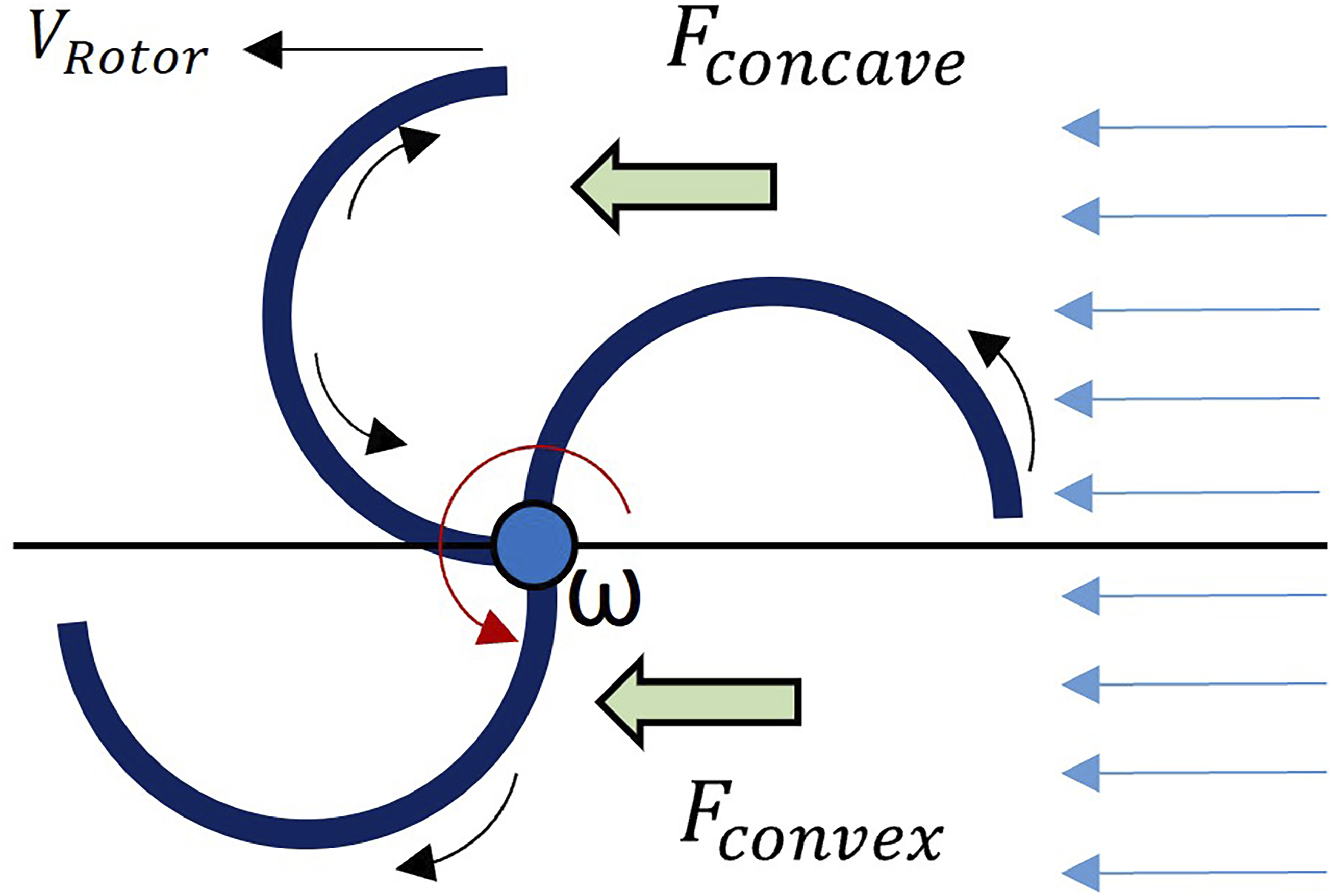
A study examining data from several research articles, tests, and analytical sources indicated that the integration of two turbines is the most effective method for harnessing wind energy, as depicted in Figure 3. Furthermore, installing each turbine on individual fundamental shafts produced greater power than placing them on a single shaft. The torque and power generated by a helical Savonius turbine upon wind impact are described by (1) and (2) respectively (Wardach et al., 2020). While the torque (T) and power (P) produced by the H-Darrieus wind turbine are given by (3) and (4) respectively. CAD design of 2 stage VAWT, Imran et al. (2022).


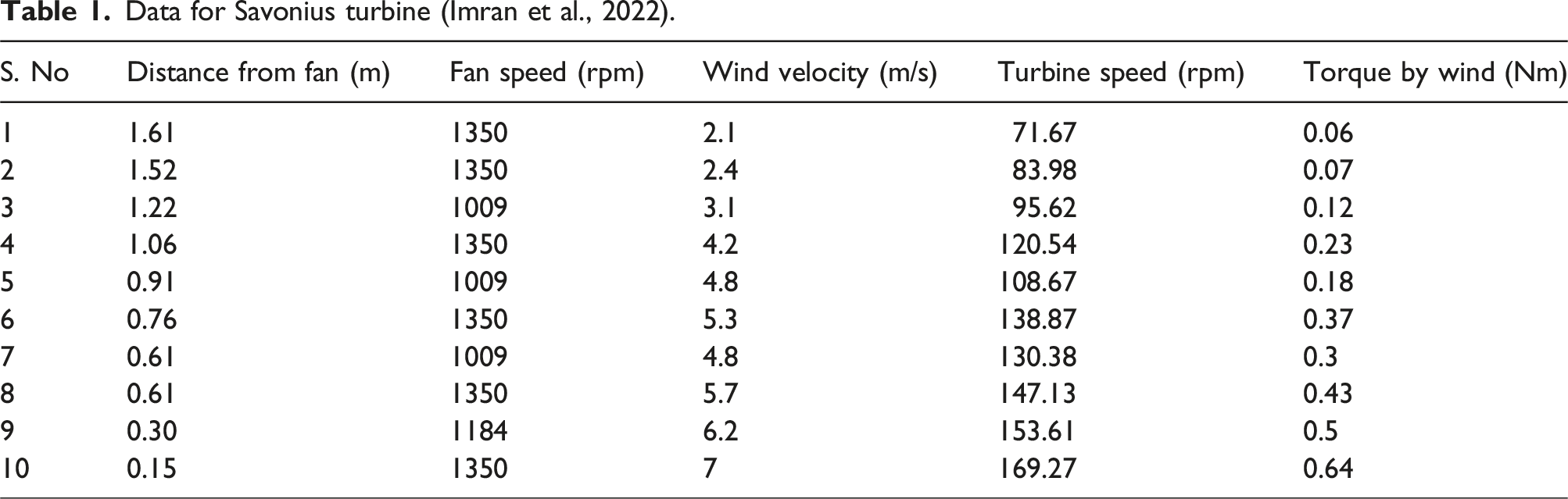
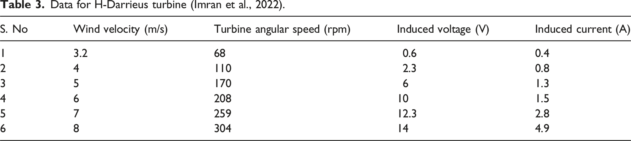
The H-Darrieus turbine was affixed above the Savonius turbine, as illustrated in Figure 4. Screw rods linked the lower ends of the H-Darrieus turbine’s rods to the top ends of the Savonius turbine’s supporting rods. The higher ends of these support rods were affixed to the base plate of the H-Darrieus turbine using bolts. The information for the Savonius Turbine and H-Darrieus Turbine is presented in Table 1 and Table 2, respectively. The experimental data in Imran et al. (2022) indicated that the Savonius turbine exhibited the lowest starting torque in comparison to the H-Darrieus turbine, which demonstrated superior efficiency at elevated wind speeds. The multistage turbine exhibited optimal performance in both high and low traffic conditions. Multi-stage vertical-axis wind turbine, Imran et al. (2022). Data for Savonius turbine (Imran et al., 2022). Data for H-Darrieus turbine (Imran et al., 2022).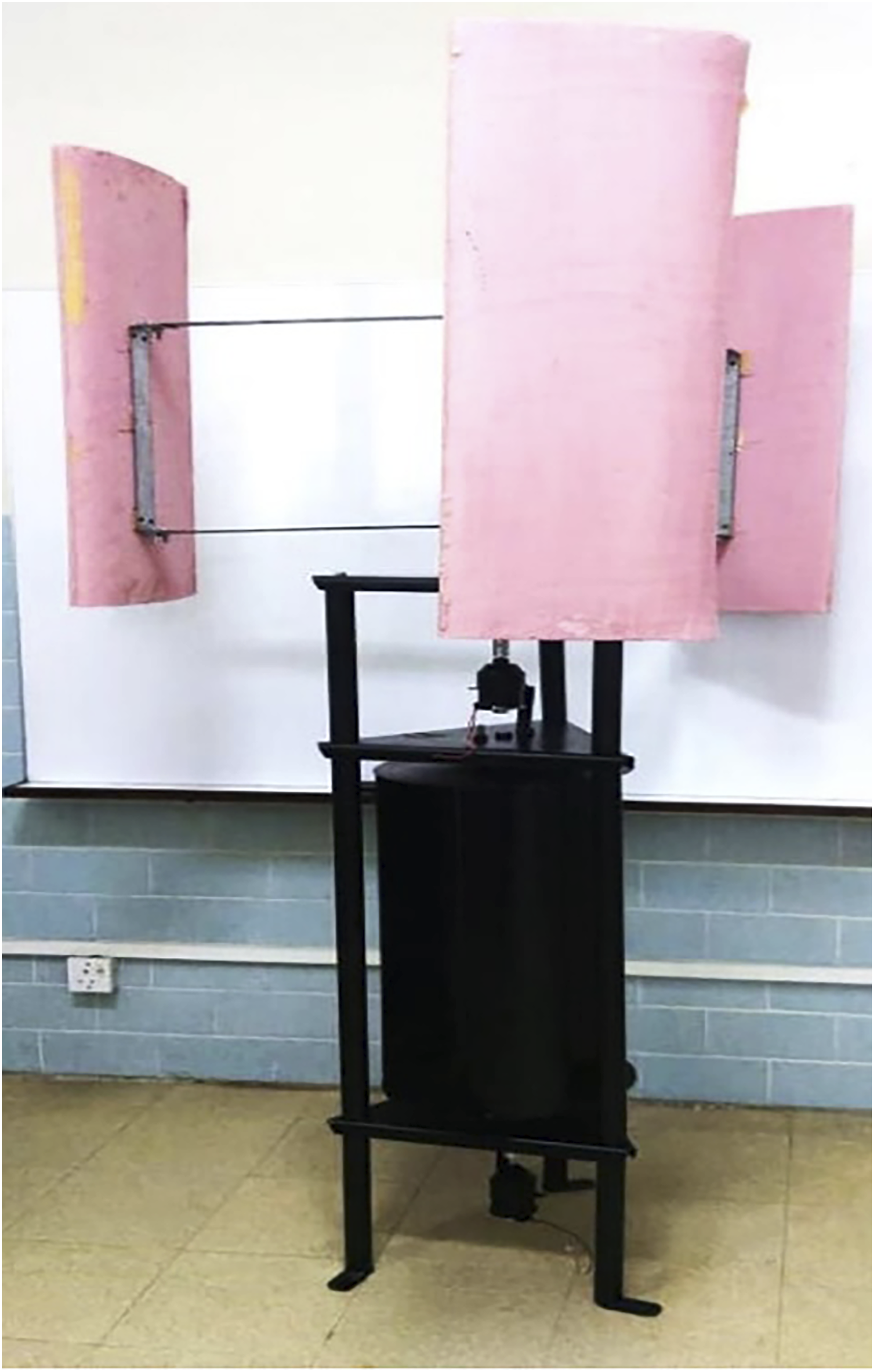

Data for H-Darrieus turbine (Imran et al., 2022).
Data for Savonius turbine (Imran et al., 2022).

The two-stage turbine design discussed above, combining a Savonius rotor and an H-Darrieus rotor capture at higher wind speeds, is particularly suitable for environments with highly variable and generally low wind velocities such as urban highways and roadside installations. However, the use of conventional generators as reported by reported by Imran et al. (2022) poses a significant limitation due to their poor performance at low rotational speeds and the requirement for external excitation to initiate power generation. These generators typically exhibit low efficiency and high cogging torque under such conditions, undermining the potential benefits of the dual-stage turbine. To address this critical bottleneck, a specialized generator is required, one that is capable of efficiently converting low-speed mechanical input into electrical energy without reliance on external power. This necessitates the design of a novel low-rpm PMSG, tailored to match the torque and speed characteristics of the two-stage vertical-axis wind turbine system. The following section presents the design, simulation, and performance evaluation of this custom generator, optimized for operation in the 250–350 rpm range and directly coupled with the turbine for efficient decentralized energy generation.
Proposed low-rpm generator
Renewable energy use requires a low-rpm generator for several reasons. Traditional high-speed generators require 1500 to 3000 rpm to create the necessary magnetic field and require a lot of initial electrical energy. These parameters are unsuitable for low wind speeds, which are common in renewable energy sites. Some regions have wind speeds as low as 3.47 m/s, making high-speed turbines inefficient. Thus, generators that convert lower spinning speeds into electrical energy with less initial energy are needed urgently.
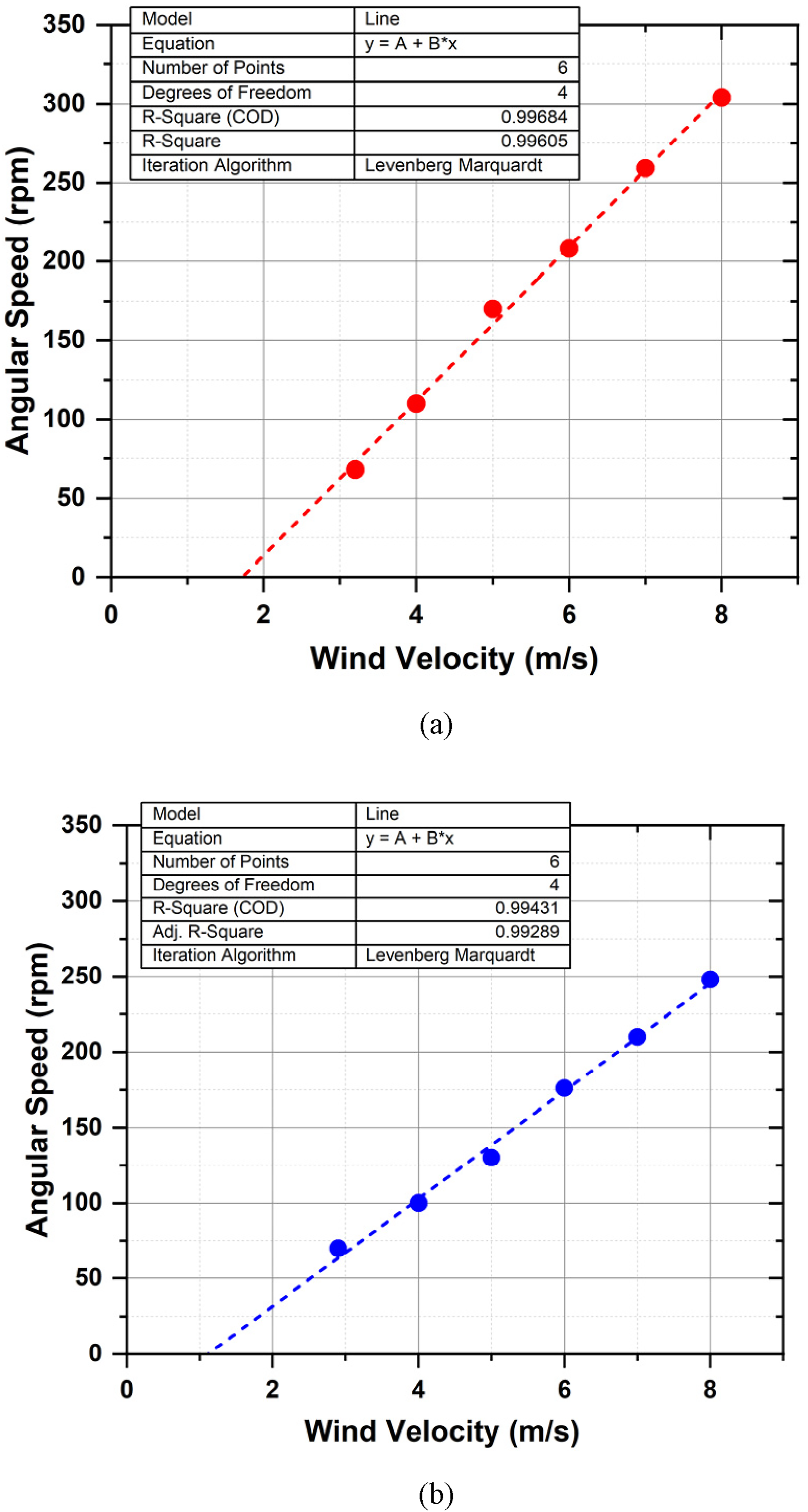
The proposed novel generator is connected to the Savonius and H-Darrieus turbines and the angular speed data points as given in Table 1 and Table 2 are plotted w.r.t the wind velocity as displayed in Figure 5. The turbine angular speed based on corresponding wind velocity shows a linear curve fit on the data points. The proportionality factor for both the turbines is slightly different from each other. The H-Darrieus turbine angular speed tends to be faster w.r.t the wind velocity at lower wind velocity compared to that of the Savonius turbine. Linear interpolation was implemented to observe the correlation between the wind velocity and the blade’s angular speed for both the types of turbines as provided in Figure 6. The linear fit function, the R-squared value, and the standard deviation are also included. Figure 7 shows the curve fit of induced voltages and currents for H-Darrieus Turbine and Savonius Turbine listed in Table 3 and Table 4 respectively. Angular speed with wind velocity of Savonius and H-Darrieus turbines. Curve fitting (a) H-Darrius Turbine (b) Savonius Turbine. Curve fitting (a) Induced voltages (b) Induced currents.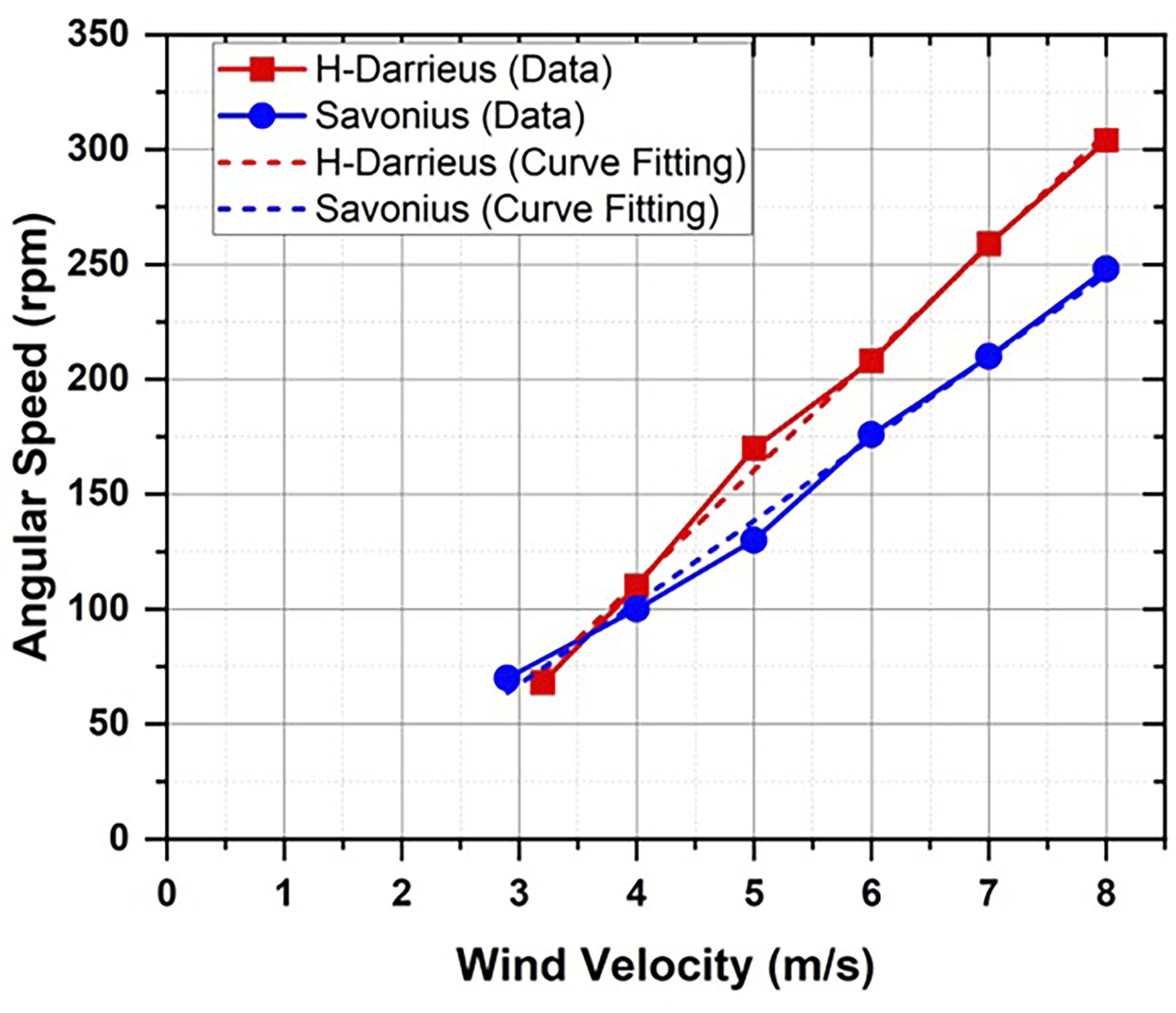

Topology design
The outer rotor configuration of the PMSG is optimized for efficient operation at low rotational speeds. The outer rotor configuration can be directly connected to the turbine shafts. This study discusses the installation of two PMGMs at either end of the turbine shaft. The machine configuration has 24 slots and 4 poles, as provided in Figure 8. The external stator configuration can be directly connected to the turbine. The rotor topology design of the low-rpm generator encompasses numerous critical factors intended to enhance its efficacy for low-speed applications. The generator’s modest dimensions, with an outside diameter of 102 mm and a shaft diameter of 100 mm, were chosen to facilitate seamless integration into the wind turbine system while preserving space and airflow. The air gap between the rotor and stator assemblies was reduced to 1 mm, enhancing magnetic flux density and minimizing losses to optimize energy conversion efficiency. The principal parameters of the machine are reported in Table 5. Machine design layout of PMSG. Topology and operating modes of PMSG.

Working principle
The operational principle of the low-rpm generator centers on its capacity to efficiently transform low-speed mechanical input into electrical energy. This relation is derived in the form of output electrical power produced by the generator by a factor of efficiency.


For efficiency maximization, the generator losses and the loss factors are calculated. Total loss of the PMSG is given as Winding Layout of proposed PMSG.


The concept utilizes the characteristics of Permanent Magnet Generators (PMGs), which do not necessitate an initial electrical supply to produce a magnetic field, in contrast to conventional high-speed generators. This characteristic renders PMGs exceptionally efficient and economical, particularly appropriate for low-speed applications like wind turbines.
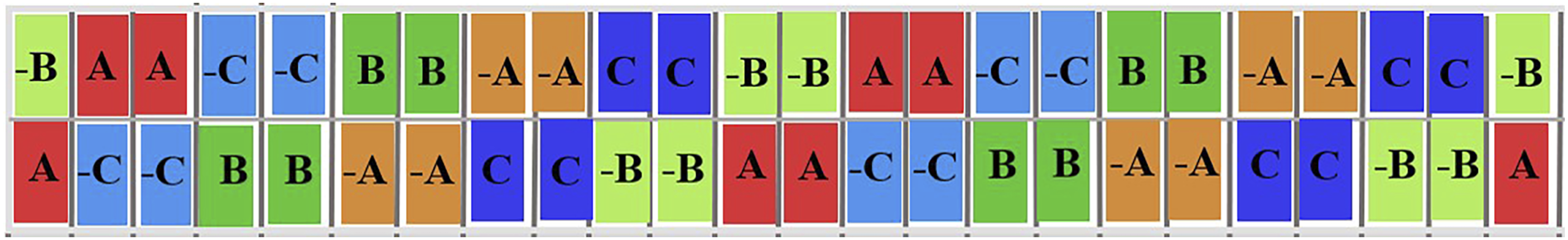
The generator employs NdFeB magnets, recognized for their elevated magnetic flux density, which markedly improves the generator’s efficiency and power production. The NdFeB used in this paper are grade N42, due to their strong magnetic strength, good temperature tolerance up to 80°C and affordable. The magnets are deliberately positioned within the stator assembly to enhance magnetic field strength and facilitate efficient energy conversion. The stator design features several slots accommodating the windings, which are arranged to enhance the induced voltage and current output, thus optimizing the generator’s efficiency at low rotational speeds. Figure 9 illustrates that the winding configuration within the slots is meticulously organized to guarantee balanced distribution, with careful attention to elements such as wire gauge and insulation. Table 5 presents the design factors of an electrical PM generator.
Performance analysis of the proposed generator
The generator design has been modeled using ANSYS Maxwell. The design process of high-speed electrical machines entails ongoing iterations of electromagnetic principles. The engineered PMSG will be affixed to the turbine shaft. Upon the initiation of turbine rotation, the rotor of the engineered PMSG concurrently begins to rotate with the shaft. As the rotor rotates, the magnetic field lines intercept the coils of the stator.
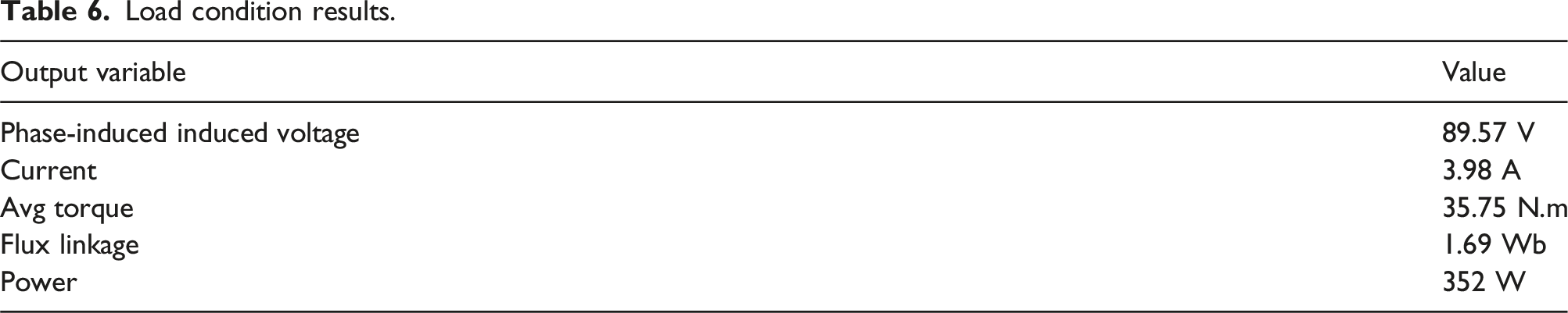
The alteration in the magnetic field, or flux, within the stator coils transpires because of the relative movement between the rotor and the stator. The revolving magnetic field generated by the rotating PM in the rotor is coupled with the coils in the stator, leading to the induction of 3-phase EMF in the stator, as illustrated in Figure 10. As the generator’s spin accelerates, the voltage within the generator rises. The root mean square (rms) value of the induced voltage is 88.5 V, significantly exceeding the voltage at the maximum rpm of Imran et al. (2022). As the turbine’s rpm escalates, the size of the rate of change in magnetic flux concurrently intensifies. Induced voltage at 250 rpm.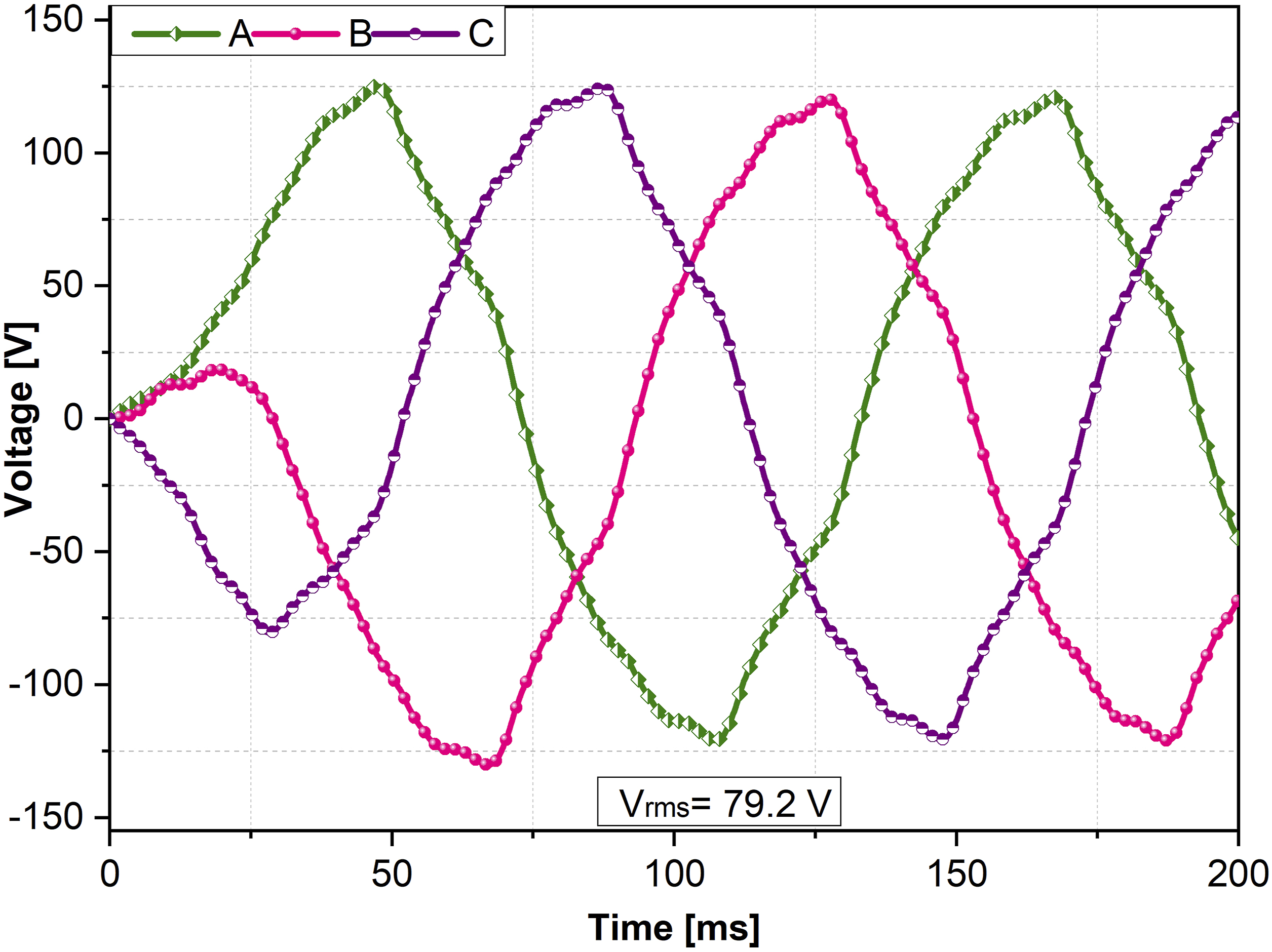
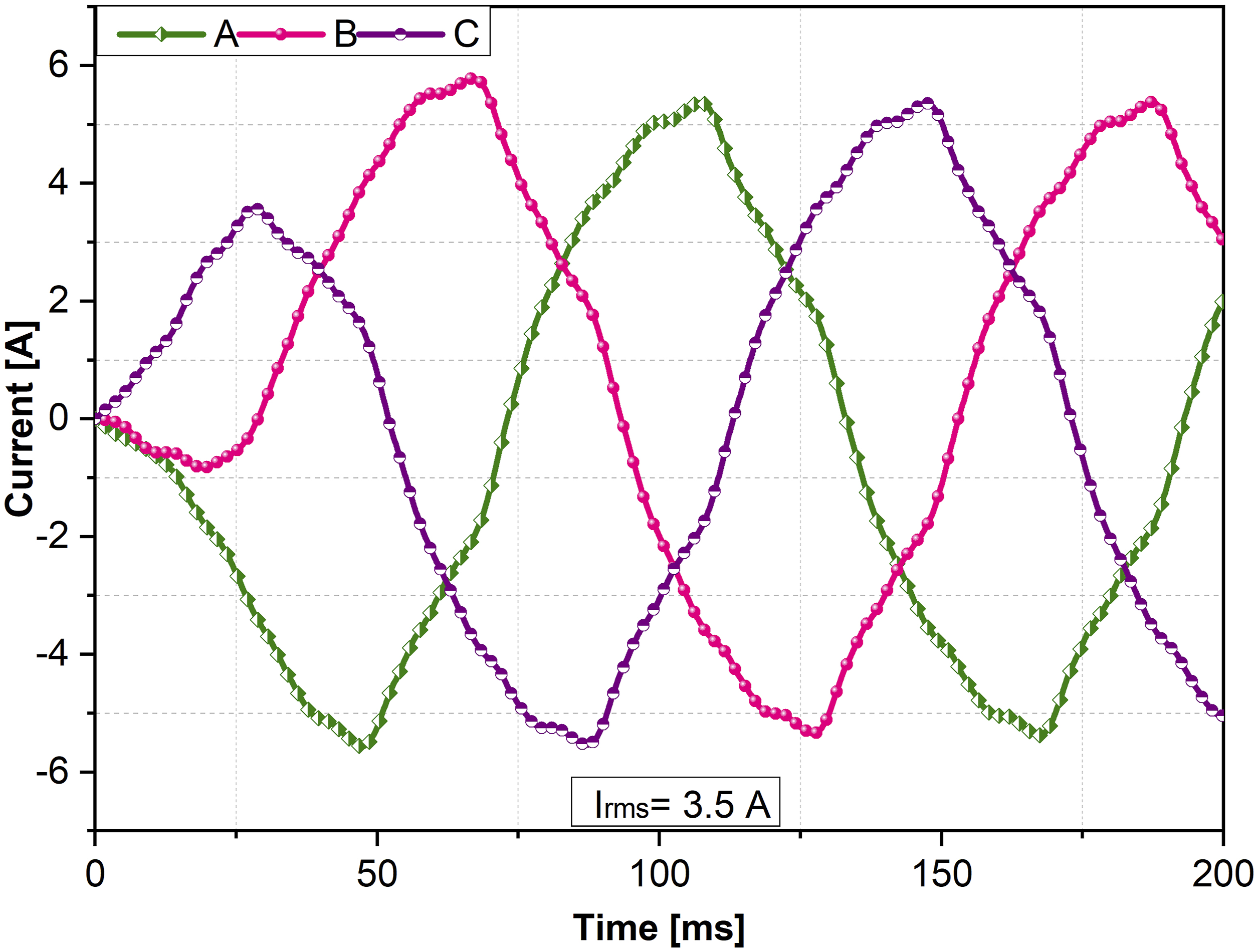
The flux linkage in the machine at 250 rpm is depicted in Figure 11, with an rms value of 1.7 Wb. Upon the induction of voltage in the stator windings, current will flow if the machine is coupled to a load. The (rms) value of the current is 3.9 A, as illustrated in Figure 12. The current value significantly exceeds the current flow in Imran et al. (2022) at around 250 rpm. The direction and quantity of the current are contingent upon the connected load and the circuit’s impedance. Should the turbine maintain its rotation, it will perpetuate voltage induction and current generation. The output voltage is contingent upon the rotational speed. The highest speed of the H-Darrieus turbine is 900 rpm, while the helical Savonius turbines have a maximum speed of 400 rpm. Induced flux at 250 rpm. Induced current at 250 rpm.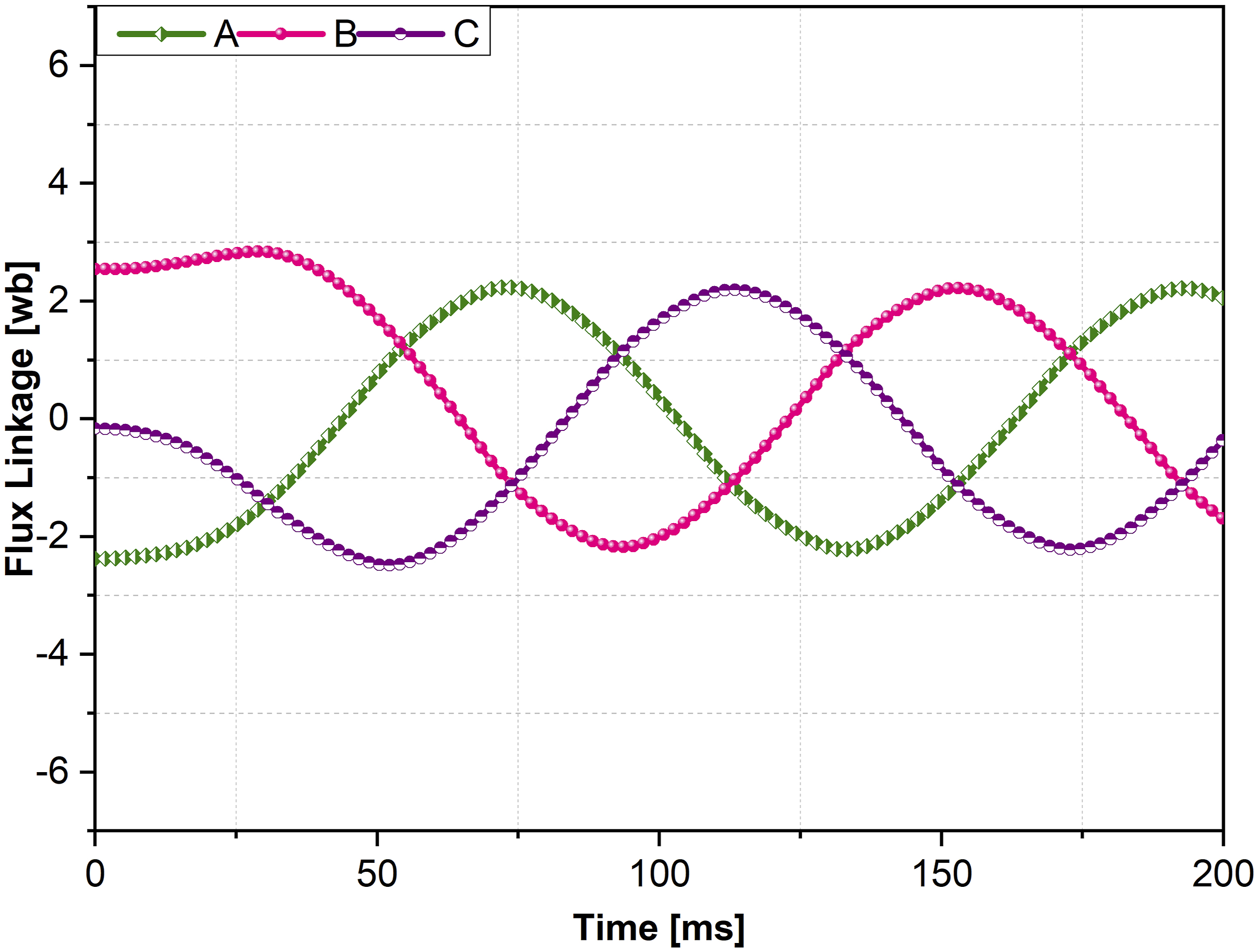
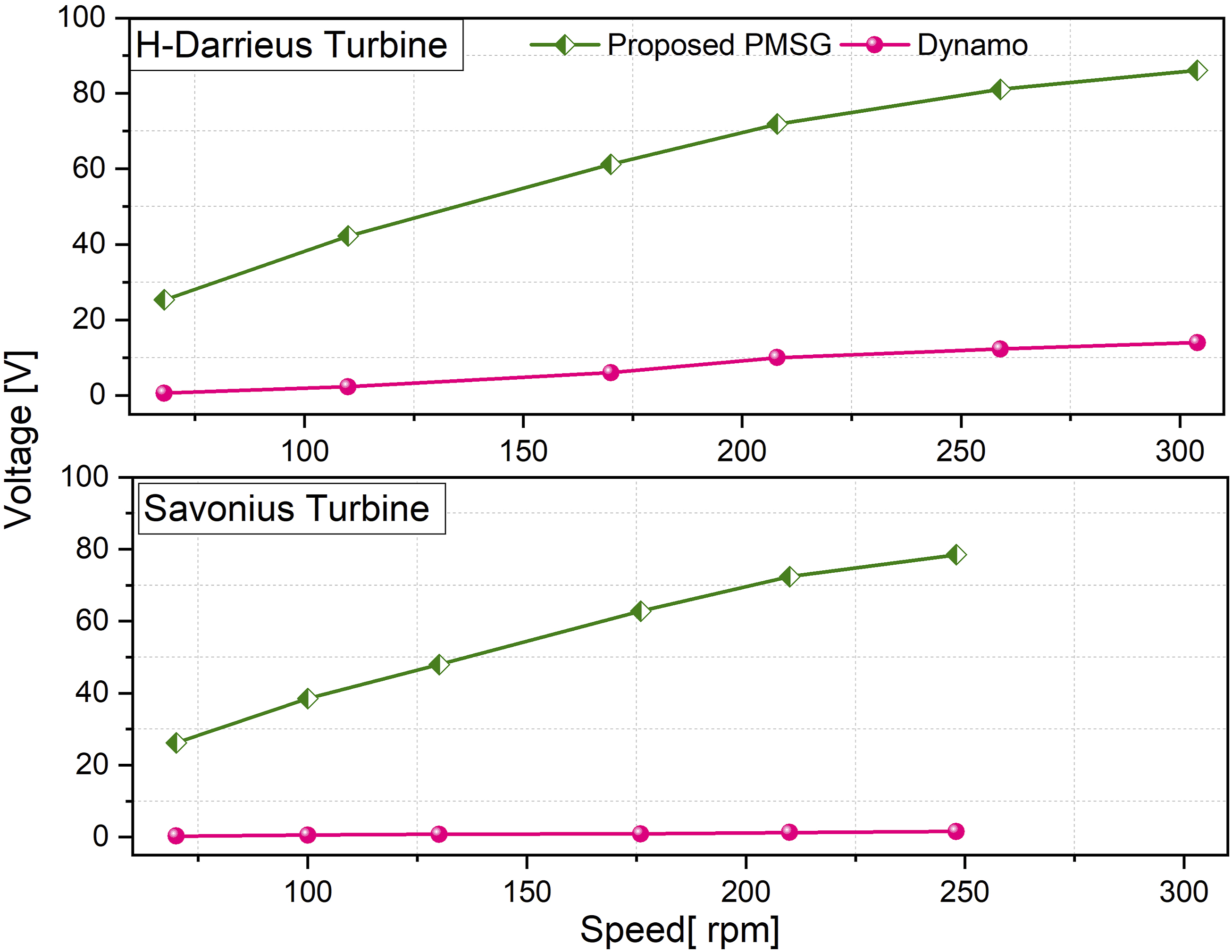
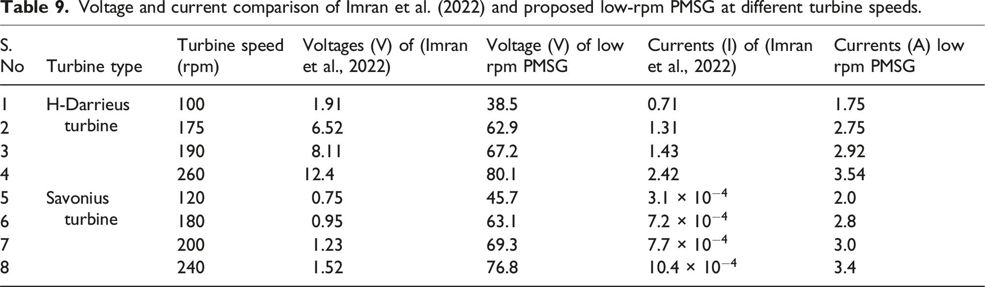
The two-stage turbine of Imran et al. (2022) will be situated on the highway; its rotation speed will vary between high and low, contingent upon traffic conditions and configuration. The voltage and current waveforms are presented for 250 rpm, which is below the turbine’s normal speed. The induced voltages and currents will exceed those depicted in Figures 10 and 12, respectively. Additionally, two planned generators will be affixed to the turbine shafts, as illustrated in Figure 13, each producing electric power independently for both turbine stages. The voltages and currents of the proposed PMSM at various rpms are compared with those from conventional brushed DC generator, as detailed in Tables 3 and 4 for both turbines utilized in multistage turbines. The comparisons are shown in Figures 14 and 15 respectively. As shown in figures the proposed PMSG provides better induced EMF and currents compared to Imran et al. (2022) and ultimately it provides better power. Load condition parameters are of the proposed machine are listed in Table 6 these comparisons are encapsulated in Table 7. Shafts for PMSGs mounting on multistage turbines. Voltage comparison of proposed PMSG and brushed DC Generator (a) H-Darrieus Turbine (b) Savonius Turbine. Current comparison of proposed PMSG and brushed DC Generator (a) H-Darrieus Turbine (b) Savonius Turbine. Load condition results. Voltage and current comparison of (Imran et al., 2022) and proposed low-rpm PMSG at different turbine speeds.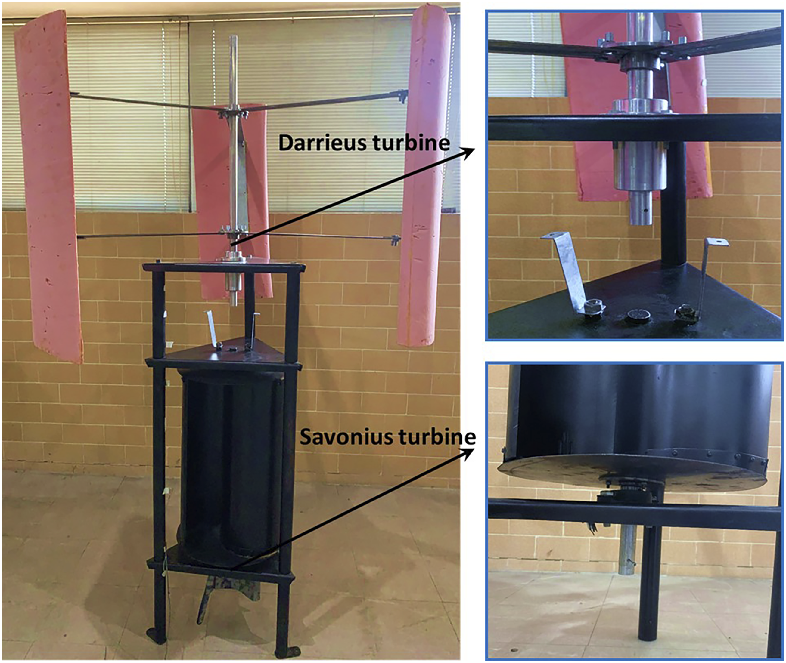


Performance comparisons with the PMSG (Roga et al., 2022).
Voltage and current comparison of Imran et al. (2022) and proposed low-rpm PMSG at different turbine speeds.
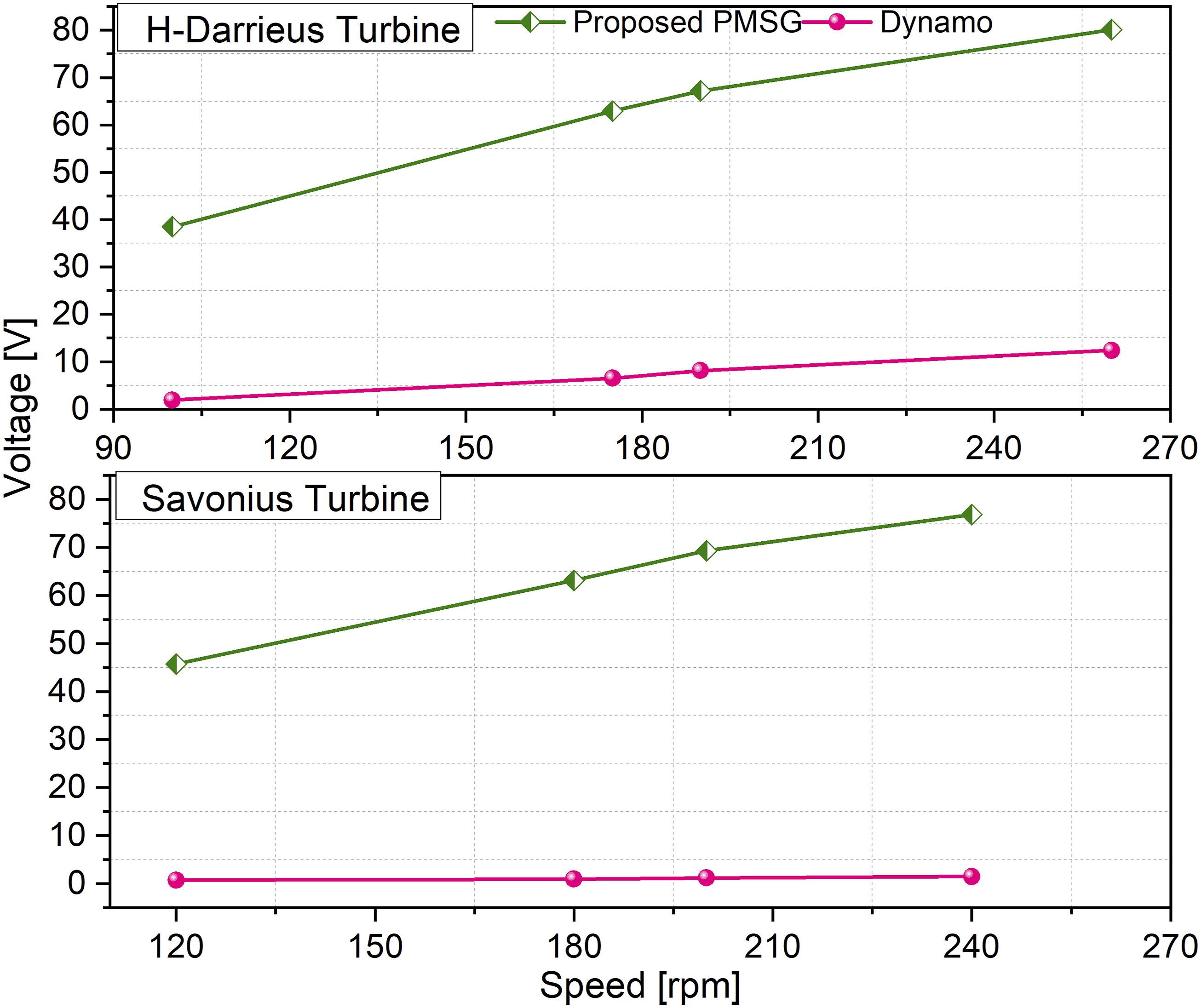
Voltage comparison of proposed PMSG and brushed DC Generator based on new experimental rpm measurements (a) H-Darrieus Turbine (b) Savonius Turbine.
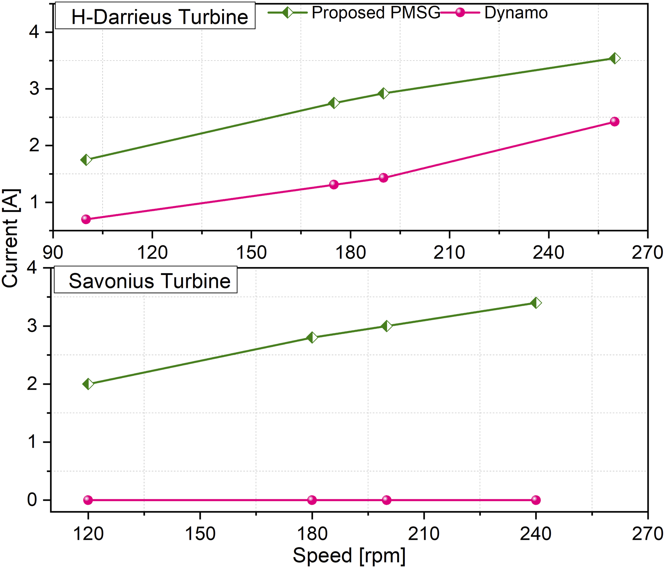
Current comparison of proposed PMSG and brushed DC Generator based on new experimental rpm measurements (a) H-Darrieus Turbine (b) Savonius Turbine.
By comparing Figure 14 with Figure 16 for voltage and Figure 15 with Figure 17 for current, it can be observed that the trends of voltages and currents for the H-Darrieus turbine and the Savonius turbine remain consistent. This also verifies that the experimental speeds obtained from the two-stage turbine were appropriate, even though the voltages and currents of the proposed PMSG were obtained using ANSYS Maxwell.
In the future, the power output of both PMSGs can be combined using the steps shown in Figure 18. The system begins with the AC voltage generated by each PMSG being converted to pulsating DC through an AC-DC rectifier. This rectified voltage is then smoothed using a capacitor to reduce ripple, resulting in a stable high-voltage DC output. Working-principle-flowchart of the electrical circuit for combining power.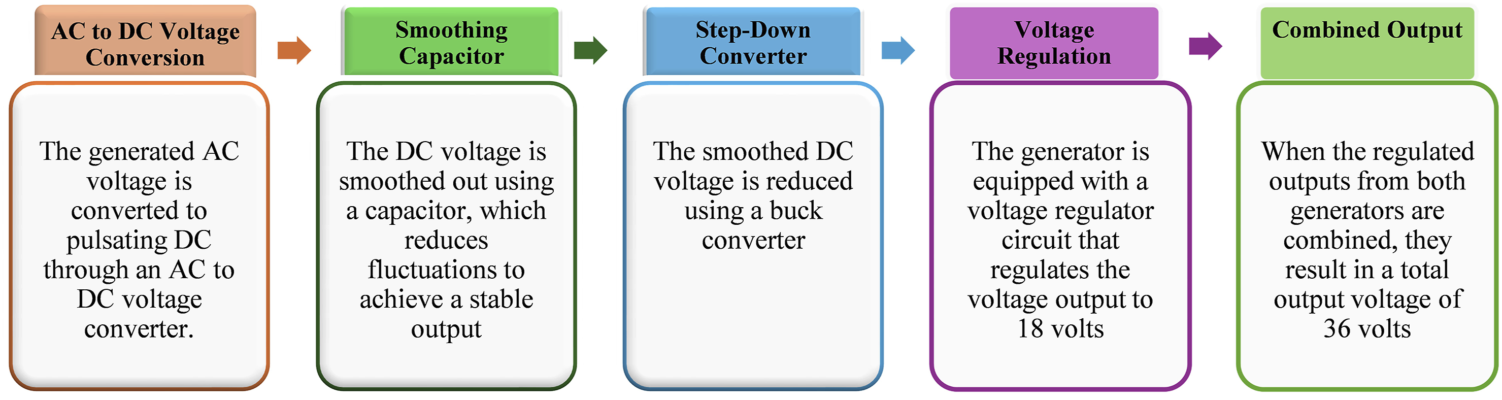
For DC-based applications, this smooth out DC voltage can be stepped down using DC buck converter to achieve a regulated 18V output per generator. When the outputs of both generators are combined, the system delivers a total of 36V DC, suitable for integration into DC microgrids or energy storage systems.
Given the generator’s speed range of 250–350 rpm and power output up to 470 W, heat generation is moderate. Passive air cooling is used, which is sufficient for low-speed, low-power applications. The outer rotor design helps expose the stator windings to air, and copper coils with good thermal conductivity reduce heat buildup. For higher temperatures or continuous heavy use, cooling can be improved by adding small fan blades or heat sinks. However, initial tests showed that passive cooling is enough for roadside and off-grid applications, confirming the design’s thermal suitability.
Conclusion
This paper proposed a low-rpm PMSG for a two-stage wind turbine. The two-stage turbine is a hybridization of H-Darrieus and helical Savonius turbines, designed to enhance the efficiency of a basic multistage VAWT. This configuration employs multiple rotors of one or more types of VAWTs. The H-Darrieus section of the two-stage turbine is well-suited for small vehicles, while the helical Savonius section is more suitable for heavy vehicles.
The proposed PMSG design presented in this paper is an optimal choice for both low and high-rpm applications. It operates effectively from 50 rpm to 900 rpm, which is the maximum speed of the turbine, and its efficiency and power output improve further as the rpm increases. Therefore, installing these two-stage wind turbines on highways would be beneficial for energy conversion at higher rpms. Results demonstrated a significant performance improvement over the previously used conventional brushed DC generator and PMSG. Compared to the outputs of Imran et al. (2022), the proposed PMSG achieved an average induced voltage increase of over 250% and current gain exceeding 300%, reflecting a substantial improvement in energy conversion efficiency at low wind speeds.
In the future, two such PMSGs will be fabricated, and the rpm of the two-stage turbine will be further enhanced. Multiple PMSG units from the two-stage turbine to a common DC bus, implementing MPPT control algorithms, and investigating integration with microgrids or energy storage systems to enable reliable power delivery. Experimental validation of the proposed concept, along with additional research, will be presented in a future study.
Footnotes
Acknowledgments
The authors acknowledge the support of the GIK Institute of Engineering Sciences and Technology and the Higher Education Commission of Pakistan under project No. NRPU-20-14813.
Author Contributions
Conceptualization, Arsalan Arif, Taqi Ahmad Cheema and Abid Imran.
Data curation, Ghulam Jawad Sirewal, Mohammad Fazail Bangash, Muhammad Hashim and Abdul Rehman.
Formal analysis, Abid Imran, Muhammad Hashim and Abdul Rehman.
Investigation, Abid Imran, Ghulam Jawad Sirewal, Muhammad Hashim and Abdul Rehman.
Methodology, Arsalan Arif, Ghulam Jawad Sirewal and Taqi Ahmad Cheema.
Software, Arsalan Arif, Muhammad Hashim, Abdul Rehman and Mohammad Fazail Bangash.
Supervision, Arsalan Arif and Taqi Ahmad Cheema.
Writing—original draft preparation, Arsalan Arif, Mohammad Fazail Bangash.
Writing—review and editing, Taqi Ahmad Cheema, Ghulam Jawad Sirewal, and Abid Imran.
Funding
The authors received no financial support for the research, authorship, and/or publication of this article.
Declaration of conflicting interests
The authors declared no potential conflicts of interest with respect to the research, authorship, and/or publication of this article.
Data Availability Statement
The data will be made available upon request.