
Abstract
An advanced hybrid renewable energy system combining photovoltaic (PV) solar power and a doubly-fed induction generator (DFIG)-based wind energy conversion system is designed and simulated. The system integrates a back-to-back converter with a single-stage grid-connected inverter, combining their advantages to optimize performance. The grid-side converter (GSC) utilizes a maximum power point tracker (MPPT) algorithm based on the incremental conductance (INC) method for the photovoltaic system, while the rotor side converter (RSC) applies an indirect speed maximum power point tracker control for the wind energy conversion system, enabling efficient power extraction from both energy sources. The system employs a synchronous reference frame (SRF) control strategy to ensure high-quality power delivery to the grid, maintaining stability and minimizing harmonic distortion. Simulations carried out in MATLAB/Simulink under varying environmental conditions demonstrate the system’s resilience and efficiency in providing reliable power while achieving minimal total harmonic distortion (THD). The analysis highlights the system’s performance under different wind speeds and solar irradiance, as well as its ability to maintain grid synchronization and stabilize power output during transient conditions.
Keywords
Introduction
Energy consumption is a necessity to meet daily needs. We will mention two types of energy: fossil energy, known as reserve energy, which represents 80% of the energy consumed in the world, and green energy, known as renewable energy, which represents approximately 14% of global consumption in 2022 (Mihir and Mehta, 2024; Xu et al., 2024). Green energies have become strategic for countries because they lead to a reduction of CO2 emissions, which consequently allows energy independence (Senthikumar et al., 2023). The COVID-19 health crisis has led to a drop in energy demand, except for renewable energies. Some countries are ready to have a rate of 100% green electricity (Ghanbari Motlagh et al., 2024; Xu et al., 2024). Among the techniques used for the production of green electricity, we find hydraulic, solar, and wind energy. These last two renewable energies are our subject of study. As we know, the most promising and widely accessible sustainable energy sources are solar and wind power (Alluraiah and Vijayapriya, 2023; Mihir and Mehta, 2024; Xu et al., 2024).
The DFIG wind energy conversion system is appealing due to its low maintenance needs and excellent efficiency (Alluraiah and Vijayapriya, 2023; Samanes et al., 2020). Maximum power extraction from renewable energy sources and DC bus voltage management further increase the system’s overall efficiency, which in turn increases the system’s profitability and dependability. For years, a group of machines has been used to overcome many obstacles. The use of insulated gate bipolar transistor (IGBT) semiconductors has allowed us to implement a more practical solution (Jimenez Roman, 2023; Tharwin Kumar et al., 2023). PV modules, which combine series-parallel PV cell associations, provide increased voltage and power output (Alluraiah and Vijayapriya, 2023). Due to cloud cover and nighttime power outages, solar PV systems could experience swings in voltage and power. To achieve the lowest feasible energy cost, MPPT algorithms are utilized to extract the maximum power from PV systems as and when it is available (Mihir and Mehta, 2024; Korhan, 2023). Systems based on PV arrays and wind turbines are described separately and in combination in the literature for grid-connected systems with two-stage DC bus and DC-AC converters (Mihir and Mehta, 2024; Hadi and Aly, 2024; Benali et al., 2018; Renjith and Selvam, 2023; Arjun Kumar et al., 2021). The most popular and straightforward method for quickly extracting the harmonics from a three-phase system is the SRF (Paspatis and Konstantopoulos, 2018; Morsli et al., 2022).
Several recent studies have proposed advanced control methods for hybrid PV-wind systems. For instance, Mihir and Mehta, 2024 integrates direct torque control (DTC) with a fractional PI regulator for DFIGs and an Adaptive Neuro-Fuzzy Inference System (ANFIS)-based MPPT for PV, showing good adaptability. Similarly, Benali et al., 2018 employs a dynamic voltage restorer (DVR) with fuzzy logic to enhance low voltage ride through (LVRT) and power quality in hybrid wind–PV systems. More recently, Sahri et al., 2023 applied fuzzy-based controllers and an energy management algorithm to coordinate wind, PV, and batteries, achieving reduced THD and improved system efficiency. While these methods demonstrate strong performance, they often require complex multi-stage converter topologies, artificial intelligence-based controllers, or additional compensation devices, factors that increase implementation cost and control complexity. Pangedaiah et al., 2021 proposed a back-to-back PMSG-based hybrid system with independent MPPTs for PV and wind, reducing conversion stages but without explicit THD analysis.
In contrast, the present work introduces a simplified back-to-back converter for grid connection with SRF-based control, which combines the advantages of single-stage inverters. RSC extracts maximum power from the DFIG rotor, achieving up to 30% of the rotor’s rated power, while GSC, controlled via SRF, injects power into the grid. The PV array is directly connected to the DC-link, eliminating the need for an additional DC-DC converter and reducing system complexity. Independent control of the converters, together with a DC-link capacitor, stabilizes voltage, mitigates harmonics, and minimizes losses. The system also considers mechanical results of the DFIG, including rotor speed, torque, and extracted mechanical power, correlating them with electrical responses to demonstrate the impact of turbine dynamics on DC-link stability, grid injection, and overall power quality. Overall, this topology combines the efficiency and simplicity of single-stage grid-connected inverters with flexible reactive power management and reliable integration under varying solar and wind conditions.
This research aims to enhance the performance, stability, and power quality of hybrid PV/wind DFIG-based renewable energy systems connected to the grid (Sahri, 2023; Kumar Tiwari et al., 2018). By developing and validating innovative control strategies and topologies, the study addresses critical challenges related to dynamic operation, harmonic mitigation, and efficient energy management under variable environmental conditions. The major objectives of the suggested system’s research are as follows: • The proposed hybrid PV/wind DFIG-based system will combine the dynamic control capabilities of a back-to-back converter with the efficiency and simplicity of a single-stage grid-connected inverter, utilizing an SRF and MPPT-based control strategy to deliver high-quality power at the point of common coupling (PCC) (Benzoubir et al., 2025; Zhang et al., 2020; Morsli et al., 2022; EL Sayed et al., 2025). • Test single-stage topology in the hybrid system using SRF control strategy to provide high-quality power in different meteorological scenarios. • To create a PV-DFIG configuration that is both economical and efficient, with fewer control loops. • A new topology for hybrid wind and photovoltaic systems aims to achieve optimal and efficient control over the various sources, improve the quality of power supplied to the AC grid by controlling the voltage and frequency of the grid, and guarantee service continuity. • To increase total system efficiency, the wind and PV systems’ MPPTs must also be gathered. • Using Matlab/Simulink, the performance characteristics waveform are shown to demonstrate the hybrid system’s efficacy, resilience, and efficiency under various operating situations. • To significantly reduce variations in DC-link voltage and GSC power. • To guarantee the steady operation of the DC side while offering frequency assistance to the AC side.
Achieving these objectives will contribute significantly to the development of robust, efficient, and grid-compliant hybrid renewable energy systems, promoting higher integration levels of clean energy sources into modern power grids.
The remainder of this paper is organized to systematically present the modeling, control, and performance evaluation of the proposed hybrid PV-wind energy system. The next section introduces the overall system configuration and explains the fundamental operating principles of the integrated renewable energy system. This includes a high-level description of how the photovoltaic and wind subsystems interact with the power conversion components and the grid. The following section focuses on the PV generator, presenting detailed modeling approaches for solar cells and panels. It further examines the influence of environmental parameters such as solar irradiance and temperature on PV performance. The section also discusses the implementation of an MPPT algorithm to optimize energy extraction under varying climatic conditions. Subsequently, the wind energy conversion subsystem is discussed, beginning with a mathematical model of the wind turbine. It also includes the MPPT strategy tailored for wind power maximization. Additionally, it provides a comprehensive model of the DFIG, which forms the core of the wind generator, and analyzes its steady-state behavior under typical operational scenarios. The next section presents the converter system responsible for energy conditioning and interfacing with the grid. This section describes the control strategies for the RSC and the GSC, as well as the role and modeling of the DC-link capacitance, which ensures voltage stability and power flow continuity between the subsystems. Another section outlines the simulation framework, including the key scenarios considered and the parameter sets used for assessing system performance. These scenarios reflect realistic environmental and operational conditions to validate the robustness of the proposed models and control methods. The subsequent section provides a detailed discussion of the simulation results, divided into mechanical and electrical aspects. The mechanical performance of the DFIG is analyzed, followed by an evaluation of the electrical output of the PV system, the behavior of the DC-link voltage, the quality and stability of the output power, and the system’s overall efficiency under dynamic conditions. Finally, The conclusion summarizes the main contributions of the work, highlighting the advantages of the hybrid system configuration and the control strategies employed. It also discusses potential improvements and identifies future research directions aimed at further enhancing the performance and scalability of hybrid renewable energy systems.
System description and operating principle
The grid-connected hybrid PV/wind renewable energy conversion system, with variable wind speed and irradiance, consists of photovoltaic panels, a double-fed induction generator driven by a fixed-angle-blades wind turbine, and power converters. The stator side windings of DFIG are connected directly to the grid because the currents are injected into the grid as they synchronize (EL Sayed et al., 2025), and the rotor side windings are controlled to exploit the energy, employing two bidirectional power converters named back-to-back, which operate in pulse width modulation (PWM) (Mihir and Mehta, 2024; Hadi and Aly, 2024; Tharwin Kumar et al., 2023). It is the most widely used in wind energy conversion, given the advantages it brings. The proposed modification is to integrate the PV system into the DC bus of the back-to-back converter, to use the grid-side converter as a multi-source inverter (Jimenez Roman et al., 2023; Hadi and Aly, 2024; Arjun Kumar et al., 2021; Sahri et al., 2023). In this article, we will focus on the individual modeling of each element of this conversion chain, namely: • The PV system and its MPPT control (Sarvi and Azadian, 2022). • The wind turbine and its control system are designed to maximize and limit power output at both low and high wind speeds. • The DFIG, which has a stator directly connected to the network, and a rotor connected with a rectifier (RSC) that allows the application of commands that control the powers generated by the stator, and to obtain a continuous voltage for the DC bus (Arjun Kumar and Shivashankar, 2022; Kebbati and Baghli, 2023). • The DC bus that contains the connection point of the PV generator, and a DC filter capacitor (Sahri, 2023; Pangedaiah et al., 2021). • The inverter (GSC) is an effective solution for improving the power factor on the grid side and adjusting the DC bus (Pangedaiah et al., 2021; Arjun Kumar and Shivashankar, 2022; Kebbati and Baghli, 2023). • RL filter connects the GSC to the grid (Kebbati and Baghli, 2023).
As shown in Figure 1, this topology offers the advantages of a single-stage grid-connected PV system. To do this, we will describe the mathematical models of each element of the system (Mchaouar et al., 2022; Guler and Irmak, 2019; Hadj Mihoub Sidi Moussa et al., 2024). Block diagram of grid-connected PV/DFIG hybrid system.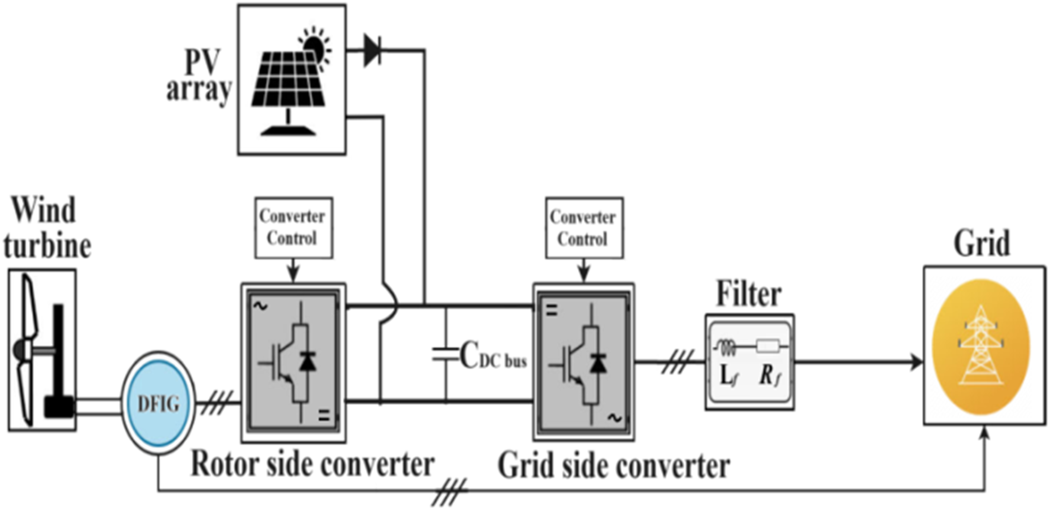
Description of the PV generator part
Solar PV models
A photovoltaic array is made up of several solar cells that produce charge carriers in response to photons striking the array. If the photon’s energy exceeds the semiconductor’s band gap, the electrons are released and cause the current to flow. In addition to the standard monocrystalline solar cells, a variety of polycrystalline solar cells are reasonably priced. Much study has been done up to this point in an attempt to determine an accurate solar equation that may be correlated with real-world behavior. Therefore, the PV arrays’ cell properties are not up to par. A current source I
ph
and a diode D are connected in parallel to make the ideal PV array architecture. The circuit for a single solar cell, consisting of a current source and a shockley diode with parallel resistance R
p
and series resistance R
s
, is shown in Figure 2 (Tharwin Kumar et al., 2023; Korhan, 2023). The total current of the solar cell is the sum of the current source and the diode current. Equation (1) illustrates the mathematical equation for current I for a single solar cell (Varun Sai et al., 2024; Mihir and Mehta, 2024; Kacimi et al., 2023). Solar cell equivalent circuit.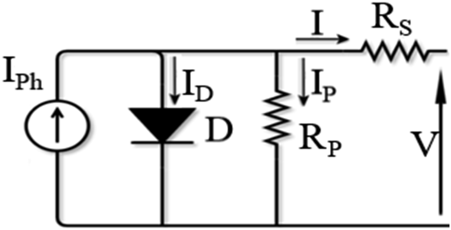


Several mathematical models are used to simulate the operation of a photovoltaic generator. Several mathematical models are used to simulate the operation of a photovoltaic generator. These models differ in the calculation method and the number of parameters involved in the current-voltage characteristics. In our case, we have chosen a simple model requiring the parameters given by the manufacturer. The I-V characteristic of this model is illustrated below (Varun Sai et al., 2024; Mihir and Mehta, 2024):

The influence of solar irradiation and temperature on the functioning and Characteristics of the PV panel
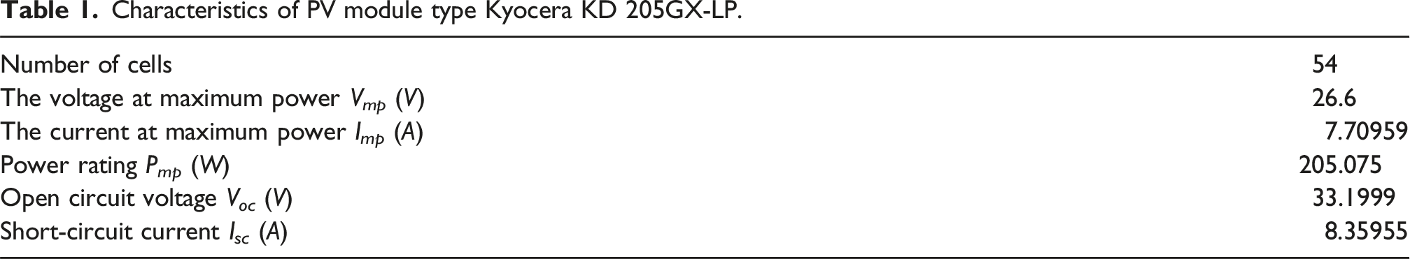
To study the influence of illumination G and temperature T° on the characteristics of the panel, one is varied and the other is fixed at its reference value; the simulation results are shown in Figures 3 and 4. These characteristics relate to the Kyocera KD205GX-LP, the solar photovoltaic module chosen in this article, and Table 1 summarizes the parameters of this panel (Hadj Mihoub Sidi Moussa et al., 2024; Hadj Mihoub Sidi Moussa et al., 2023). I-V and P-V curve characteristics of the PV panel at 25°C. I-V and P-V curve characteristics of the PV panel at 1 kW/m
2
. Characteristics of PV module type Kyocera KD 205GX-LP.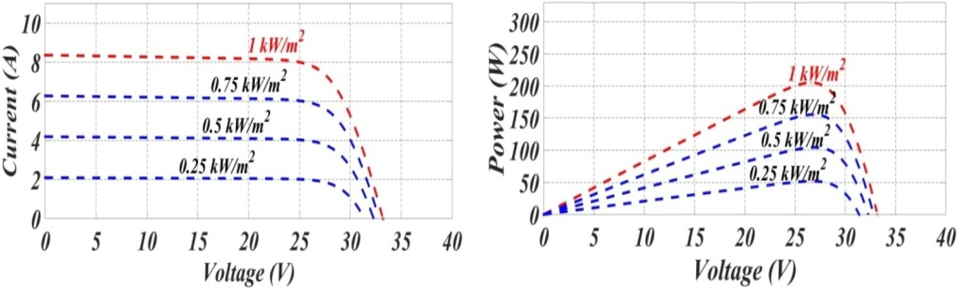
The simulations in Figure 3 below present the influence of solar illumination and sunshine on the operation of the PV panel, which is the power and current characteristics as a function of voltage for various irradiations and at an ambient temperature of 25°C (Varun Sai et al., 2024; Benali et al., 2018).
According to the simulation results, we notice that the short-circuit current I
sc
, when the voltage is zero (V
pv
= 0), is expressed by expression (7) and is strongly linked to solar irradiation; it is directly proportional to this factor. In the situation where the current is zero (I
PV
= 0), the power P
PV
produced by the panel is zero. This is the open circuit voltage V
oc
can be expressed analytically according to formula (8). As shown in Figure 3, and contrary to I
sc
, V
oc
is slightly affected by the variation of irradiation; it increases a little with the increase of the latter, so we can conclude that the maximum power of the panel is strongly linked to the solar irradiation. The extraction of the coordinates of these two parameters is presented in Figure 5 (Varun Sai et al., 2024; Benali et al., 2018; Ahmed, 2024). PV panel parameter coordinates.

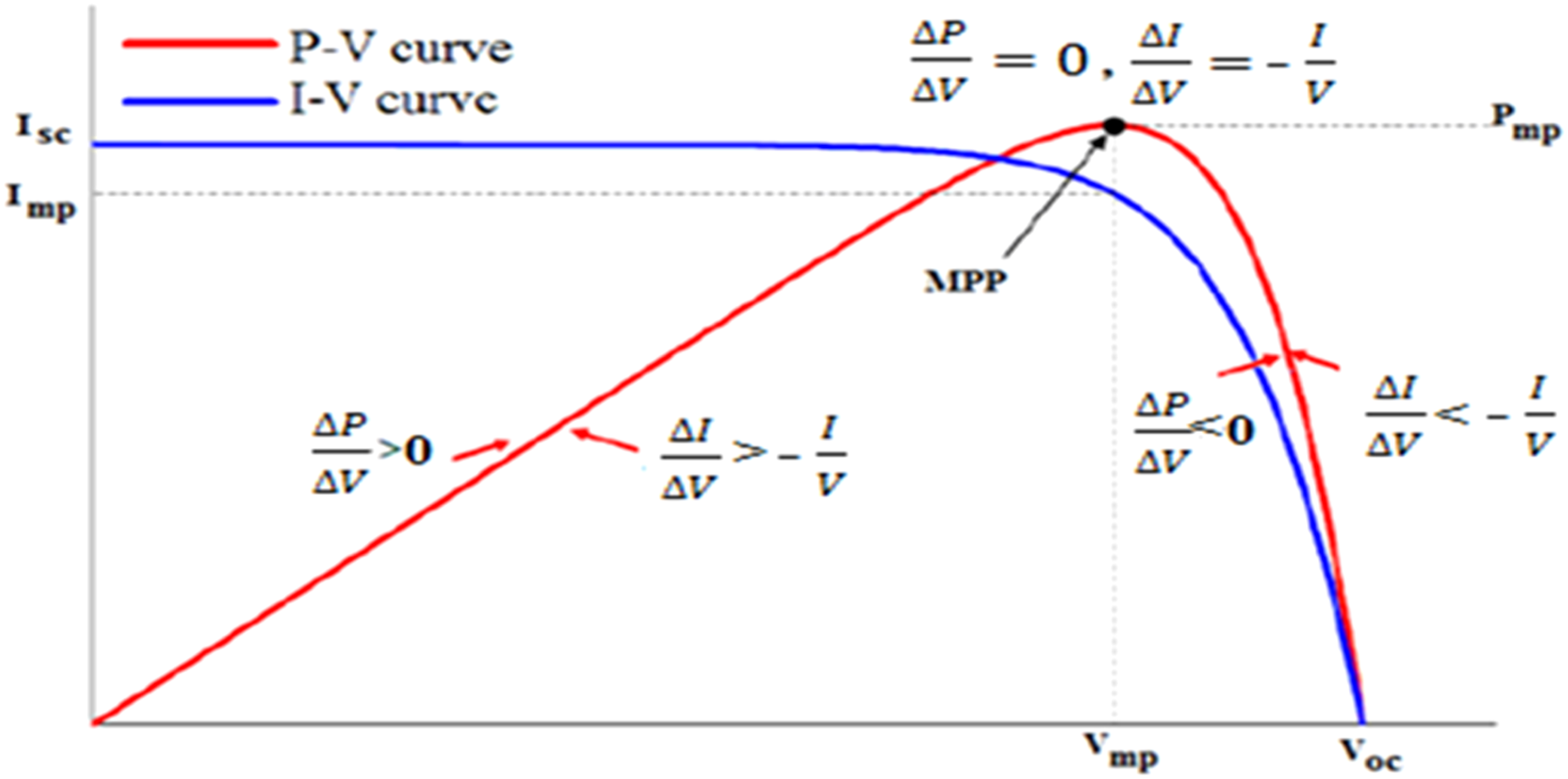
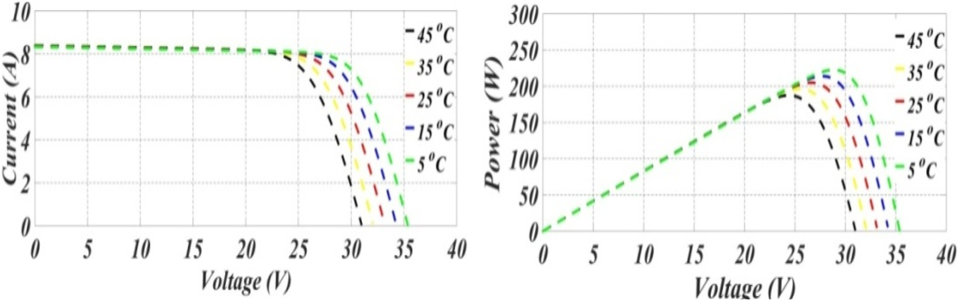
Figure 4 shows the influence of solar temperature on the operation of the PV panel, which is the power and current characteristics as a function of voltage for various temperatures, and at an ambient irradiation of 1 kW/m 2 (Mchaouar et al., 2022; Ahmed, 2024).
For the temperature, we note that the short-circuit current is not very sensitive to variations in the latter. As shown in Figure 4, we also notice that the open circuit voltage is inversely proportional to the temperature, which causes a small reduction in power.
MPPT algorithm
The characteristic of a PV generator is non-linear; it produces power at a point called the operating point, which belongs to the characteristic curve. Figure 5 illustrates the PV panel parameter coordinates, showing the P-V and I-V characteristic curves, along with the Maximum Power Point (MPP). As shown, the coordinates of this point are the operating voltage and current. As for the cell, the MPP corresponds to the operating point for which the PV generator (Varun Sai et al., 2024; Renjith and Selvam, 2023). This highlights the importance of operating the system at the MPP to get the most out of the available power. To overcome this problem, it is necessary to provide a maximum power point tracker (MPPT) controller to extract maximum power from the panel (Kacimi et al., 2023; Hadj Mihoub Sidi Moussa et al., 2024).
In this paper, the MPPT controller based on the INC algorithm employs two sensors to measure voltage V
dc
and current I
pv
. The technique is predicated on the idea that the derivative of the output power P to the DC-link module’s voltage V equals zero at the maximum power point (MPP) as presented in equation (9), which can be expressed by the voltage and current as equation (10). Where ΔI/ΔV symbolizes incremental conductance of solar panels and I/V symbolizes instantaneous conductance (Akif, 2023; Benali et al., 2018; Hadj Mihoub Sidi Moussa et al., 2024; Kumar Tiwari et al., 2018; Sarvi and Azadian, 2022).

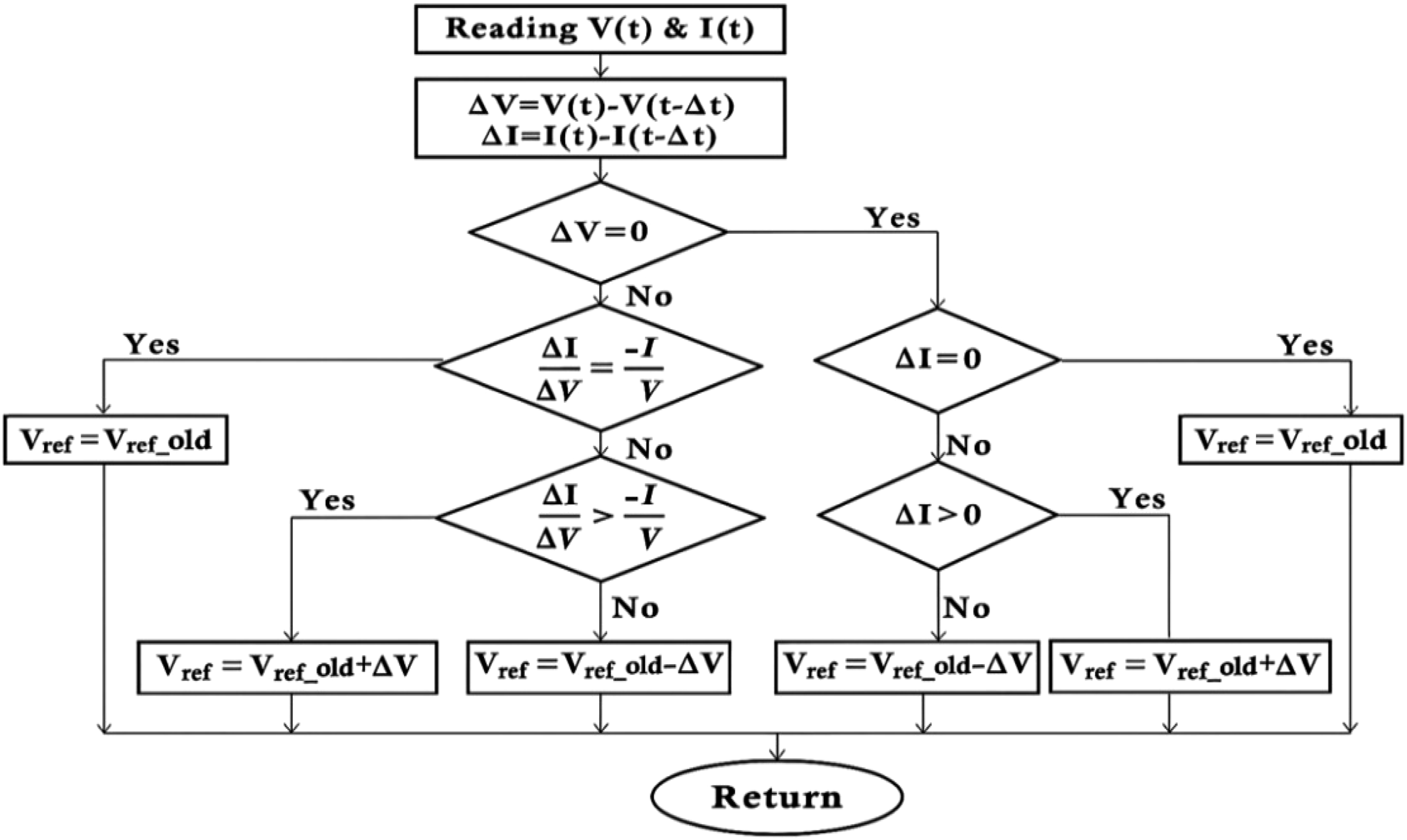
From the PV characteristic curve of the photovoltaic generator, the MPP is located at the top of the curve. Figure 6 depicts the incremental conductance (INC) MPPT algorithm, which defines the decision-making rules for adjusting the reference voltage to ensure effective MPP tracking. The operating principles of this method can be summarized as follows (Akif, 2023; Benali et al., 2018; Kacimi et al., 2023; Kumar Tiwari et al., 2018): • If the PV array is just working at the MPP, the reference voltage is unchanged. • If the PV array is running on the left side of the MPP, for the system to operate at the MPP, the reference voltage should change in the direction of the voltage increase. • If the PV array is operating on the right, for the system to run at the MPP, the reference voltage should change in the direction of the voltage decrease. INC MPPT algorithm flow chart.
Description of the wind generator part
For a wind conversion system, wind is an important element for wind conversion, as it represents the input of the system studied. The kinetic energy contained in the wind is partly recovered, transformed into mechanical energy through the turbine, and then into electrical energy through the generator, which is a DFIG type, as shown in Figure 7 (Benali et al., 2018; Al-Jodah and Alwan, 2021; Lai et al., 2025; Arjun Kumar and Shivashankar, 2022). Wind turbine.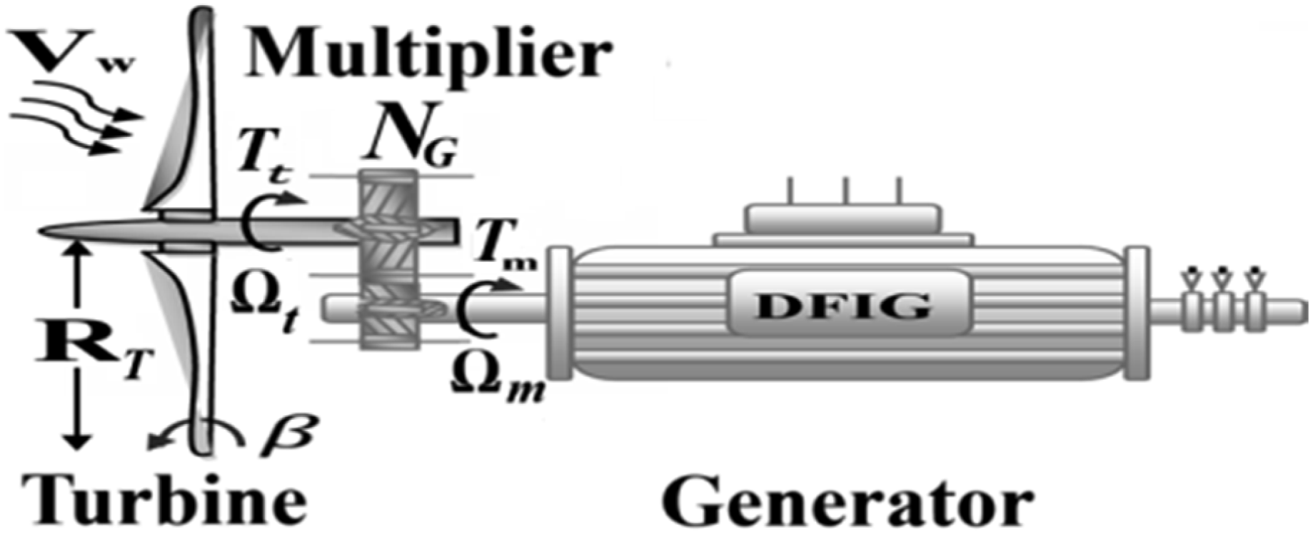
Turbine modeling
Three factors express the aerodynamic power P
aer
as wind power, as shown in equation (11). First of all, two climatological parameters that depend on the site are: ρ is the air density (about 1.22 kg/m
3
at normal atmospheric pressure and a temperature of 15°C), and V
w
is the wind speed. The third parameter is the swept area A (Mihir and Mehta, 2024; Renjith and Selvam, 2023; Arjun Kumar and Shivashankar, 2022).
The turbine captures the kinetic energy of the wind and converts it into torque, which turns the rotor blades. Due to the wind exerted on the area swept by blades and the various losses, the wind turbine can only recover a part of the wind power, which can be 59% (Arjun Kumar and Shivashankar, 2022). The aerodynamic power of the turbine P
t
recovered at the rotor level of the turbine according to Betz’s theory determines the relationship between wind energy and the mechanical energy recovered by the rotor, and is then written as equation (12) (Thomas et al., 2024; Varun Sai et al., 2024; Mihir and Mehta, 2024; Al-Jodah and Alwan, 2021; Alghamdi et al., 2024).
A is the area swept by the rotor blades and experiment as shown in equation (13). C
p
(λ,β) is the aerodynamic efficiency of the turbine, often called the power coefficient. It is a coefficient specific to each wind turbine that depends on the blade pitch angle β and the speed ratio λ, which is defined as the ratio between the linear speed of the turbine and the wind speed. Its expression is given as shown in equation (14) (Thomas et al., 2024; Varun Sai et al., 2024; Al-Jodah and Alwan, 2021; Arjun Kumar and Shivashankar, 2022).


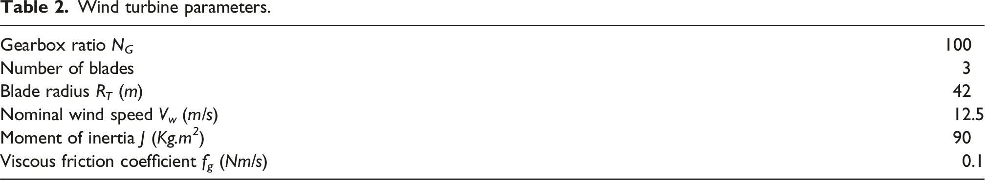
Wind turbine parameters.
A plot of the variation of this coefficient as a function of the specific speed λ for different values of the blade orientation angle β, shown in Figure 8, allows us to have the maximum point of this coefficient (C
p_max
= 0.44), which corresponds to the optimal values λ
opt
= 7.2 and β = 0. With these values, the turbine will operate with maximum efficiency and thus provide optimal mechanical power (Alghamdi et al., 2024; Kumar Tiwari et al., 2018). Power coefficient C
p
curves for different pitch blade angles β.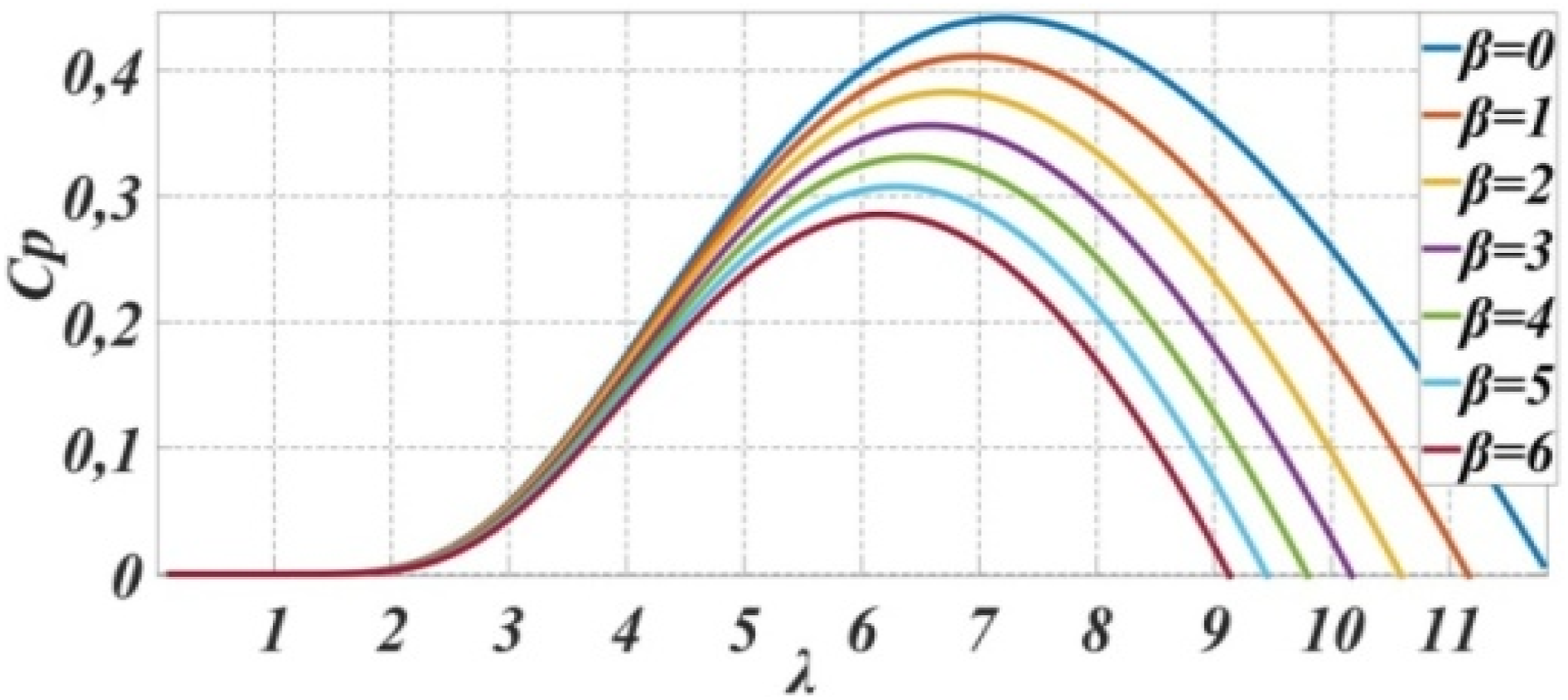
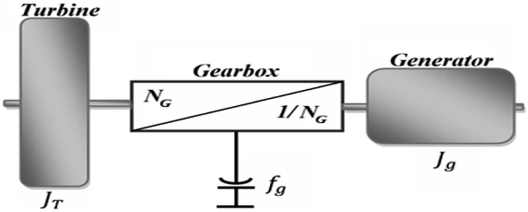
Considering the multiplier shown in Figure 7, which is a gearbox used to transfer mechanical power from the turbine to the generator while providing a higher speed and lower torque T
m
. It consists of two rotating shafts, one rotating at a slow speed Ω
t
and the other rotating at a fast speed Ω
m
; its gain is mathematically modeled by equations (18) and (19):

About the model of the mechanical shaft, we suppose: The blades have a single mass with an inertia J
t
; The inertia of the gearbox is negligible compared to that of the turbine rotor and the generator; The slow and fast transmission shafts are perfectly rigid. These assumptions allow us to represent the simplified two-mass model as shown in Figure 9, where the total inertia J given in equation (20) consists of the inertia of the blades J
t
and the inertia of the generator J
g
(Tharwin Kumar et al., 2023; Benali et al., 2018). Simplified turbine model.
As shown in equation (21), the fundamental equation of dynamics makes it possible to determine the evolution of the mechanical speed from the mechanical torque T applied to the rotor, which depends on the electromagnetic torque produced by the generator T
em
, the friction-resisting torque T
f
given by equation (23), and the torque from the multiplier T
m
(Tharwin Kumar et al., 2023; Haq et al., 2020).


By the Laplace transform, equation (24) becomes as shown in equation (25).
Therefore, from the above equations, we can establish the block diagram of the turbine, which is presented in Figure 10. Block diagram of the turbine model.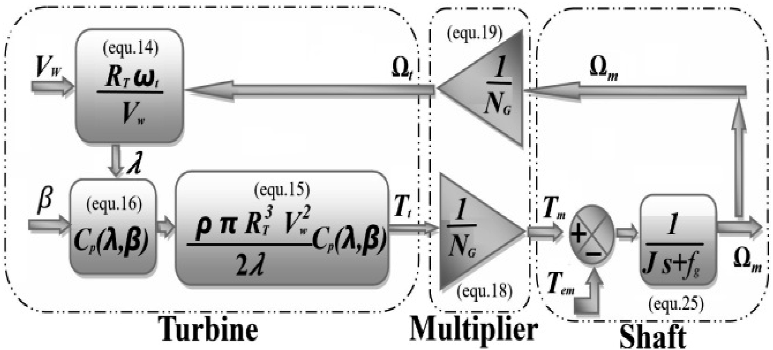
Wind turbine MPPT
It consists of determining and maintaining the turbine speed at a certain value, which allows the maximum power generated to be obtained. The method applied in this paper does not require a wind speed measurement (Al-Jodah and Alwan, 2021; Alghamdi et al., 2024). This method, called estimated reference speed control or indirect method, is based on a simple estimation of the optimal electromagnetic torque (Arjun Kumar et al., 2021; Pangedaiah et al., 2021). The wind speed will be deduced from the specific speed equation as shown in (26), and the optimum aerodynamic torque T
t_opt
will also be as in equation (27), which is proportional to the square of the rotor speed (Thomas et al., 2024; Arjun Kumar et al., 2021; Al-Jodah and Alwan, 2021; Pangedaiah et al., 2021).

V w_est is the estimated wind speed.
In a steady state, the mechanical equation becomes as in expression (28).
The expression in (29) gives the optimal electromagnetic torque T
em_opt
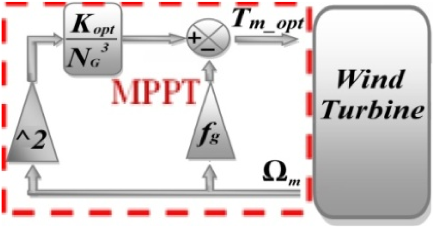
that must be imposed on the generator to ensure optimal operation of the wind turbine. The block diagram of this control structure is given in Figure 11 below (Arjun Kumar et al., 2021). Indirect speed MPPT control.
DFIG modeling
DFIG is a simple asynchronous machine with a wound rotor equipped with the brush-ring system, where the stator can be connected directly to the grid, and the rotor, composed of a three-phase winding mounted in the star, is powered through an AC-AC converter to obtain the possibility of controlling the slip of the machine (Sahri et al., 2023). The bidirectional converter utilized can be either a direct (AC/AC) or indirect (AC/DC/AC), consisting of a rectifier and an inverter, referred to as a back-to-back converter (Samanes et al., 2020; Haq et al., 2020; Gulzar et al., 2023). The fundamental idea behind how the DFIG operates is based on the principle of controlling the flow of rotor power, or the slip power S, which can be recovered and injected into the grid. The difficulty is that the frequency of the rotor currents f
r
is equal to the grid frequency f
s
, which is multiplied by the slip S as shown in equation (30) (Jimenez Roman, 2023; Mihir and Mehta, 2024).
Then,


where,
Using vector space theory to derive a dynamic model αβ, the three stator and rotor windings can be represented separately, by four αβ windings, two fixed stator windings, and two rotating windings for the rotor, giving the stator V
s
and rotor V
r
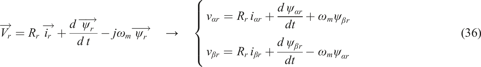
voltage equations shown in (35) and (36), respectively (Jimenez Roman et al., 2023; Varun Sai et al., 2024; Zhang et al., 2019).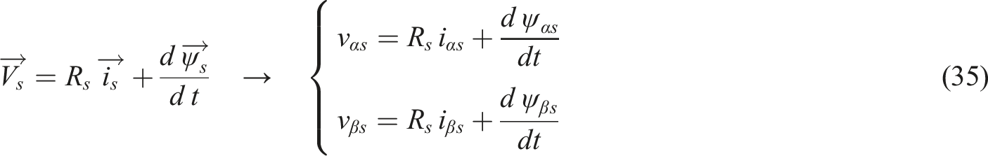


The stator and rotor inductances (L
s
, L
r
) are related to the magnetizing inductance L
m
, and the two leakage inductances of the stator and rotor (L
σs
, L
σr
), according to equations (39) and (40) (Arjun Kumar and Shivashankar, 2022).

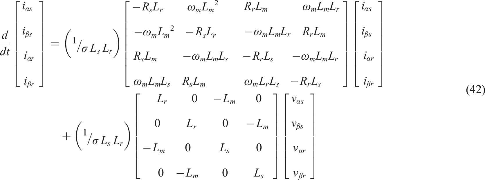
By deriving the space vector expression for the stator and rotor flux or currents in a stationary frame, they will appear as quantities in the state-space magnitudes of the αβ component, as shown in expression (41) for the flux and (42) for current (Samanes et al., 2020; Zhang et al., 2019).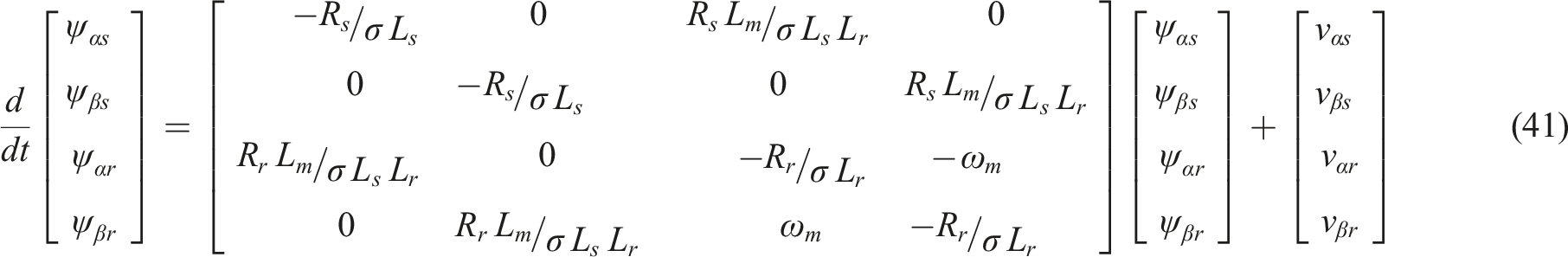

The electromagnetic torque can be found as shown in expression (44) (Varun Sai et al., 2024; Mihir and Mehta, 2024; Arjun Kumar and Shivashankar, 2022).
The state-space representation of the DFIG, expressed in terms of the stator and rotor currents as the state vector, is presented in equation (45), which is derived from equations (37) and (38) (Zhang et al., 2019).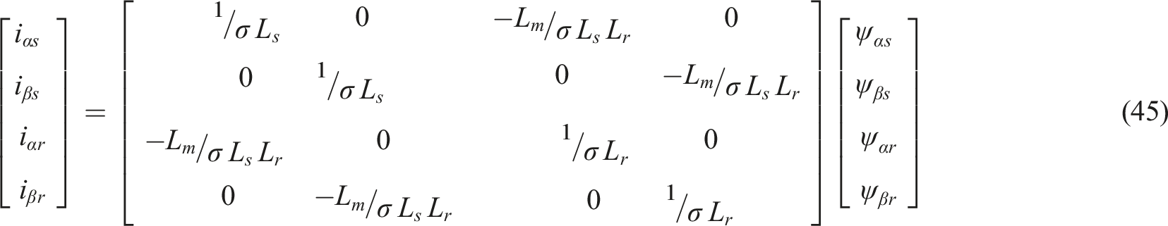
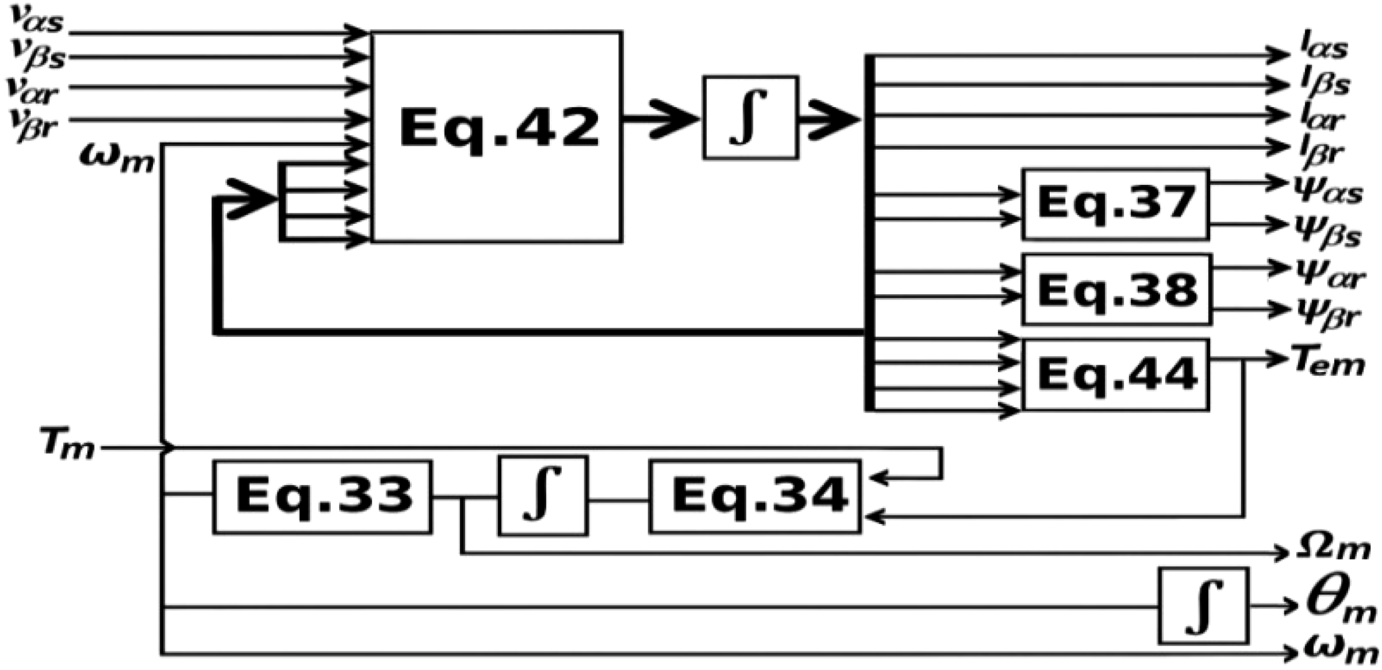
The electric active and reactive powers on the stator side and the rotor side are calculated as shown in equations (46) to (49). Figure 12 illustrates the simulation block diagram for the dynamic study of DFIG. It consists of the stator and rotor phase voltage and load torque as input. The outputs are the stator and rotor phase currents, stator and rotor fluxes, the electromagnetic torque, the speed, and the rotor angle (Benali et al., 2018; Arjun Kumar et al., 2021; Arjun Kumar and Shivashankar, 2022). DFIM simulation block diagram.


Steady-state DFIG analysis
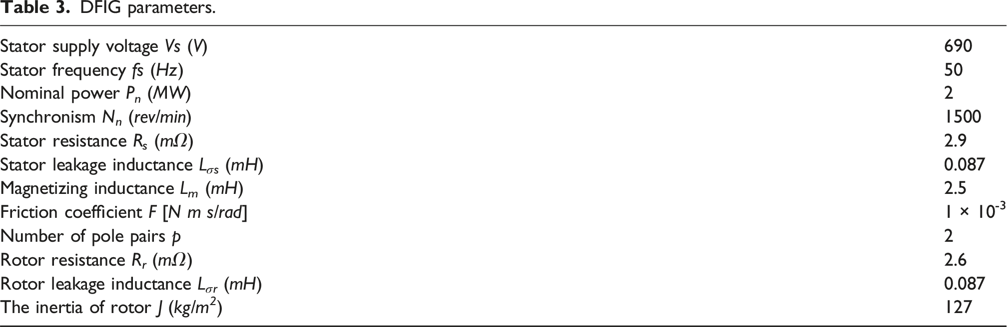
DFIG parameters.
As shown in Figure 13(b) and for the chosen DFIG, it should be noted that only in generator mode, the electromagnetic torque is negative (T
em
<0). By relating the steady-state performance analysis of the DFIM, between the plots in Figure 13, the slip shown in Figure 13(a) and the output power figures for the stator and rotor windings, Figure 13(c) and Figure 13(d), respectively, and as these plots show, at hyper-synchronism where the slip is negative, it is possible to supply power from both the stator and rotor sides to the grid if the speed exceeds the synchronous speed which is 1500 rpm, where it corresponds to 9.2 m/s for the wind speed that turns the blades, below this speed the generator is in hypo-synchronism mode (S>0), hence the power is supplied only by the stator (Mbukani and Gule, 2019). Steady-state magnitudes as a function of rotation speed: (a) slip, (b) electromagnetic torque, (c) stator active power, and (d) rotor active power.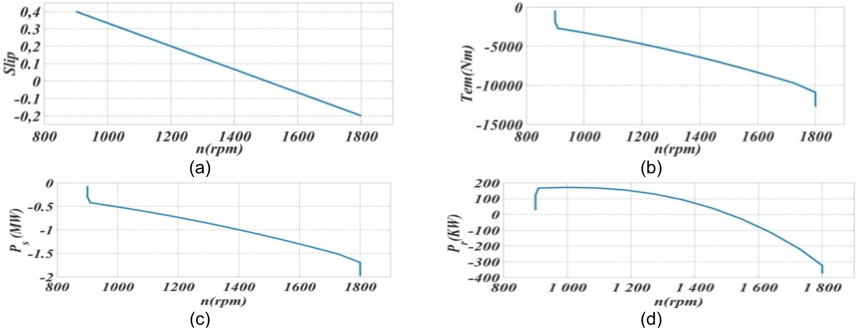
Description of the converter part
The use of power converters as an interface between renewable energies and the electrical network is necessary, especially in our case, where the DFIG is a generator that uses back-to-back converters, as a two-level bidirectional power converter topology based on PWM (Hadj Mihoub Sidi Moussa et al., 2024). A connection of a rectifier with an inverter that is sized for part of the nominal power of the DFIG, would allow the transfer and routing of the slip power to the electrical grid, and make it possible to insert the photovoltaic energy into the DC bus of this converter (Jimenez Roman, 2023; Varun Sai et al., 2024; Zhang et al., 2020; Hadj Mihoub Sidi Moussa et al., 2023).
The two-level converter shown in Figure 14 contains six controllable antiparallel diode IGBT switches. The input currents and voltages of this converter are (i
a
, i
b
, i
c
) and (v
a
, v
b
, v
c
), respectively. The line inductance (L) and the line resistance (R) are presented between the bars, measuring the voltage (u
a
, u
b
, u
c
) on the grid side and the voltage V
abc
on the converter side (Kebbati and Baghli, 2023). The converter can be modeled by writing the differential equations of each phase governing the operation of the system. This part of the research aims to have a well-regulated DC voltage and sinusoidal three-phase currents to compensate for harmonics, and to have a unity power factor (Paspatis and Konstantopoulos, 2018; Hadj Mihoub Sidi Moussa et al., 2024). Two-level inverter power circuit.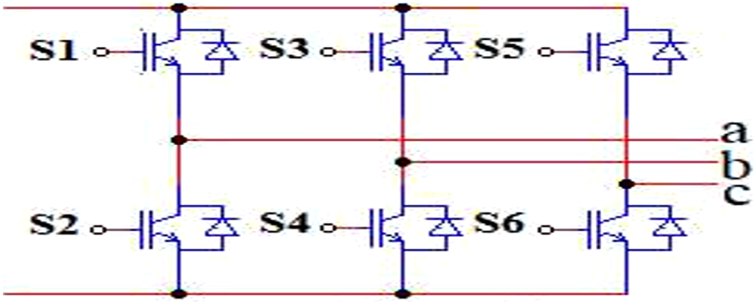
RSC control
The RSC is essential in the hybrid PV-wind system, controlling the wind turbine’s output and ensuring compatibility with the PV system’s voltage levels. It regulates the electrical torque, DC voltage (V DC ), and reactive power (Q), using the wind turbine MPPT to optimize the T em_opt shown in equation (29), to optimize energy generation while maintaining seamless integration between wind and PV sources (Varun Sai et al., 2024; Benali et al., 2018; Pangedaiah et al., 2021; Gulzar et al., 2023).
The converter control using the SRF method, modeled by formulas (50) and (51), consists of two coordinated loops for voltage and current regulation in a DFIG. The voltage loop controls active (P) and reactive (Q) power, ensuring efficient grid integration, while the current loop regulates rotor currents to follow reference values (Paspatis and Konstantopoulos, 2018; Benzoubir et al., 2025). A phase-locked loop (PLL) synchronizes with the grid to determine the reference frame angle (θ), facilitating dq transformation for simplified control (Samanes et al., 2020; EL Sayed et al., 2025). To generate the necessary voltage reference commands for the RSC using the PWM modeling method, the proportional integral (PI) controllers adjust power and current errors in both loops, where 


DC capacitance
The size of the DC capacitance and the ability of the control to track the reference voltage determine the duration of each phase of the control. One way to design the DC-link capacitor is as follows (Senthikumar et al., 2023; Pangedaiah et al., 2021):
GSC control
The grid-side converter ensures effective grid interaction by regulating DC-link voltage, stabilizing grid voltage through reactive power compensation, and minimizing harmonic distortion using PWM techniques (Benali et al., 2018; Paspatis and Konstantopoulos, 2018; Samanes et al., 2020; Hadj Mihoub Sidi Moussa et al., 2024).


As illustrated in Figure 15, the GSC control architecture is based on a cascaded structure. It includes an MPPT controller, based on the INC method summarized in Figure 6, which calculates the reference voltage v
dc_ref
for DC-link voltage regulation. The structure consists of an outer current control loop, expressed in the synchronous dq-reference frame and defined by formulas (55) and (56), and an inner DC-link voltage regulation loop, described by formulas (57) and (58), which governs the DC-link voltage dynamics (Mchaouar et al., 2022; Guler and Irmak, 2019; Pangedaiah et al., 2021). Grid synchronization is maintained through a PLL (EL Sayed et al., 2025; EL Sayed, 2024), ensuring the converter’s output remains aligned in frequency and phase with the grid, thus enabling smooth power transfer (Samanes et al., 2020; Zhang et al., 2020; Morsli et al., 2022). The control method employed is known as the SRF, which is used to generate the modulating signals required by the PWM unit (Paspatis and Konstantopoulos, 2018; Morsli et al., 2022; Mohamed et al., 2025). These signals, V
abc_ref
, are derived from the current controller outputs Vd_ref and Vq_ref, as defined in formulats (55) and (56). The PWM module then uses these three-phase reference signals to generate the appropriate gate pulses for the IGBT bridge, enabling precise control of power injection into the grid (Benzoubir et al., 2025; Kacimi et al., 2023; Hadj Mihoub Sidi Moussa et al., 2024; Badoni et al., 2023). Block diagram of the SFR method controls for GSC.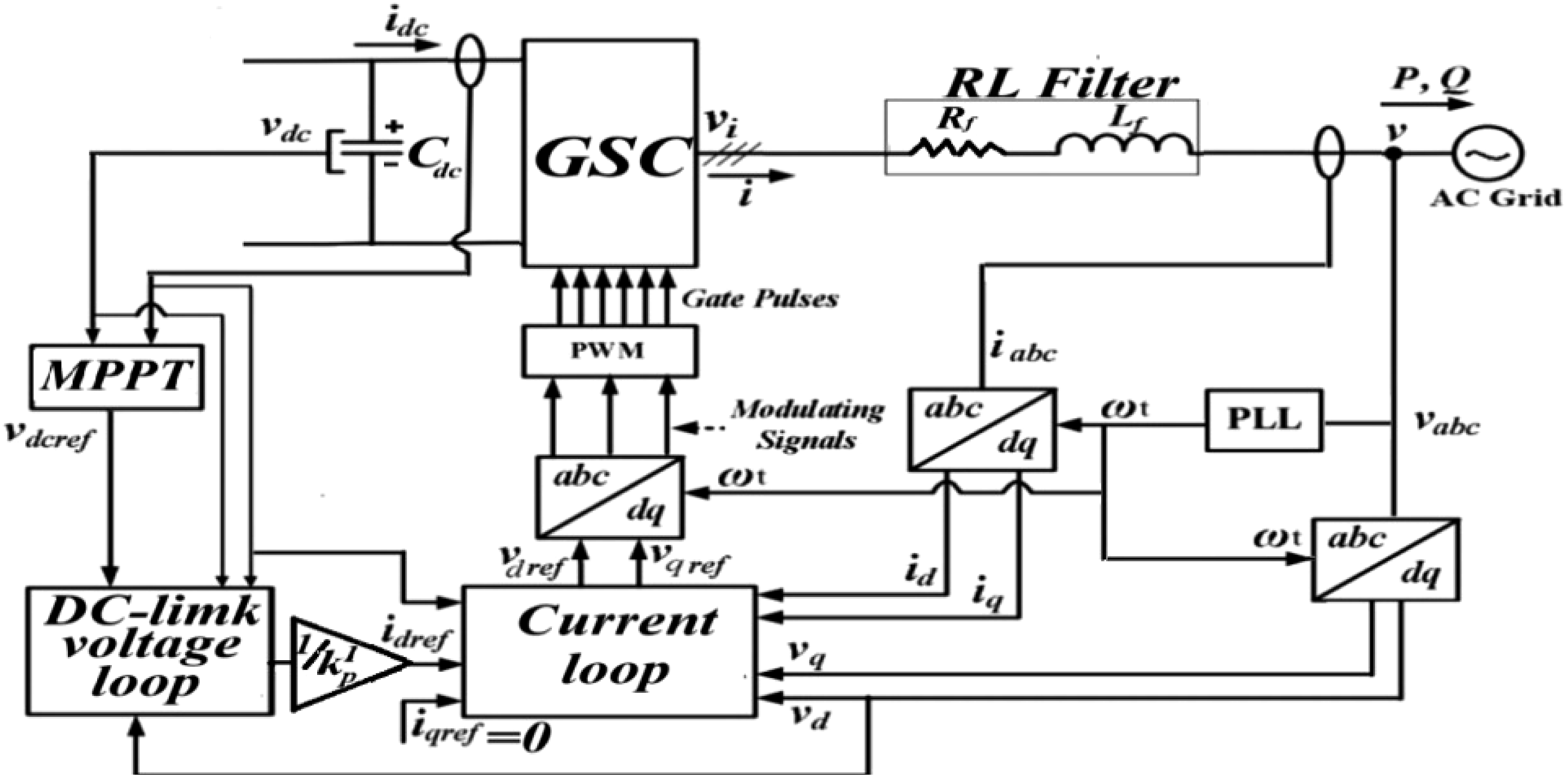
RL filter
As shown in Figures 1 and 15, the RL filter connects the inverter to the utility grid, allowing power to flow toward the grid and reducing harmonics generated by the electronic components of the system (Mohamed et al., 2025). Modeling of this filter is based on the following (59) and (60) d-q vector space equations (Kebbati and Baghli, 2023):

Scenarios and simulation parameters
The performance of the proposed PV/wind hybrid renewable energy conversion system is evaluated under various operating conditions to analyze its stability, efficiency, and adaptability. The simulation scenarios will assess the impact of different environmental and operational conditions on the system’s overall performance (Lai et al., 2025). • • • •
Rest of the simulation parameters.
Results and discussions
This section presents and discusses the simulation results obtained from the proposed hybrid system. The analysis is divided into two main parts: mechanical performance, focusing on the dynamic behavior of the DFIG, and electrical performance, emphasizing the power generation characteristics under varying operational conditions. The results provide insights into the system’s overall stability, efficiency, and responsiveness, thereby validating the effectiveness of the implemented control strategies and system design.
Mechanical results of the DFIG
The mechanical performance of the DFIG is evaluated based on the responses depicted in Figure 16, which illustrates the evolution of the electromagnetic torque T
em
, and Figure 17, which presents the corresponding rotor speed Ω
m
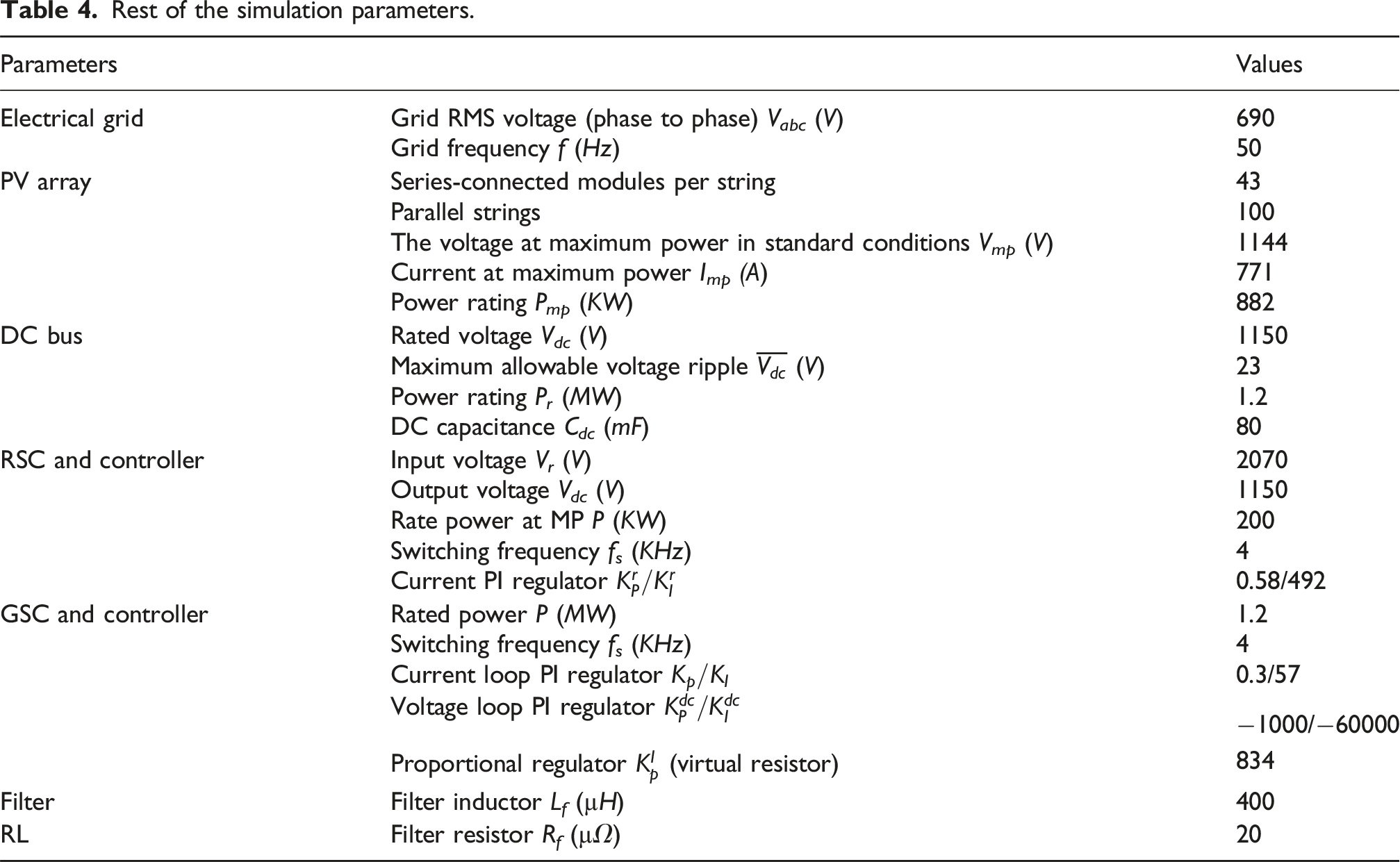
for four operating cases. The analysis focuses on the dynamic behavior, transient response, and steady-state characteristics to assess the efficacy and mechanical implications of each control strategy. Electromagnetic torque. Mechanical rotational speed at the rotor.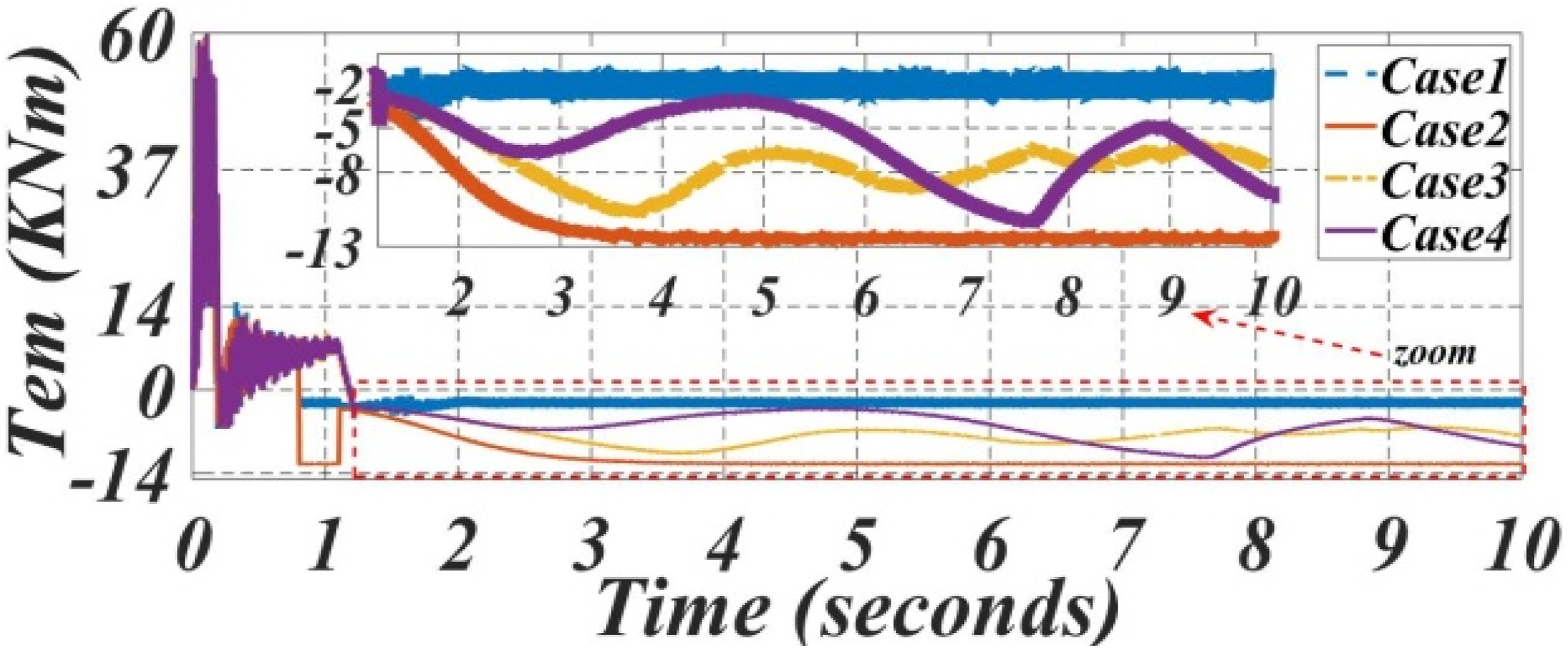
In case 1, the electromagnetic torque exhibits a highly stable and damped profile, remaining nearly constant at around 10kNm throughout the simulation. The rotor speed is also steady, maintained at approximately 90rad/s without any noticeable dynamic behavior. This response suggests a conservative, fixed-speed operation with minimal control intervention, prioritizing mechanical simplicity over dynamic performance.
Case 2 demonstrates the most efficient and well-regulated response. The torque peaks at about 40kNm during startup but quickly stabilizes to a steady-state value. Simultaneously, the rotor speed exhibits a rapid and smooth convergence to 203rad/s, without any overshoot or oscillation. These results indicate a well-tuned control system capable of delivering high responsiveness and mechanical stability.
In case 3, the torque reaches a maximum of around 30kNm and is followed by moderate oscillations before settling. The rotor speed also shows an initial overshoot, followed by damped fluctuations before reaching its steady state near 203rad/s. This case reflects a balance between response speed and damping, though the presence of oscillations suggests the need for improved controller tuning.
Case 4 displays the most unstable mechanical behavior. The torque overshoots significantly, exceeding 60kNm at startup, and continues to fluctuate with large amplitude throughout the simulation. Similarly, the rotor speed shows persistent oscillations and lacks convergence, highlighting inadequate damping and poor control design. Such instability raises concerns about mechanical stress and long-term system reliability.
The mechanical analysis reveals that the control strategy significantly affects the dynamic and steady-state performance of DFIG systems. Case 2 emerges as the most mechanically efficient, offering fast rotor speed convergence, minimal overshoot, and stable electromagnetic torque, suggesting an optimally tuned control system. Case 3 provides a balanced performance with acceptable transient behavior but shows oscillations, indicating the need for better damping and controller tuning. Case 1, though stable with minimal dynamic activity, limits adaptability to changing wind conditions, reducing energy capture efficiency. Case 4 suffers from poor mechanical performance, with high torque overshoot and rotor speed oscillations, highlighting the need for better damping and control design optimization to ensure stability and safe operation.
Electrical power results
PV system
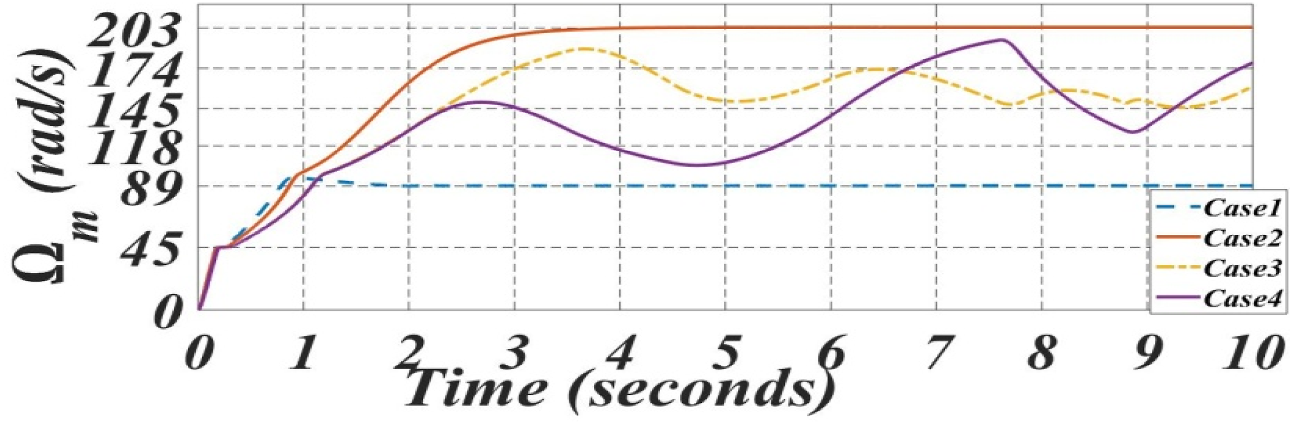
This part analyzes the dynamic and steady-state behavior of the PV subsystem within a grid-connected PV/wind hybrid system, under four different operational scenarios. The objective is to assess the effectiveness of MPPT algorithms, the level of coordination between subsystems, and the overall system stability. The evaluation is performed based on the PV current I
PV
shown in Figure 18 and PV power output P
PV
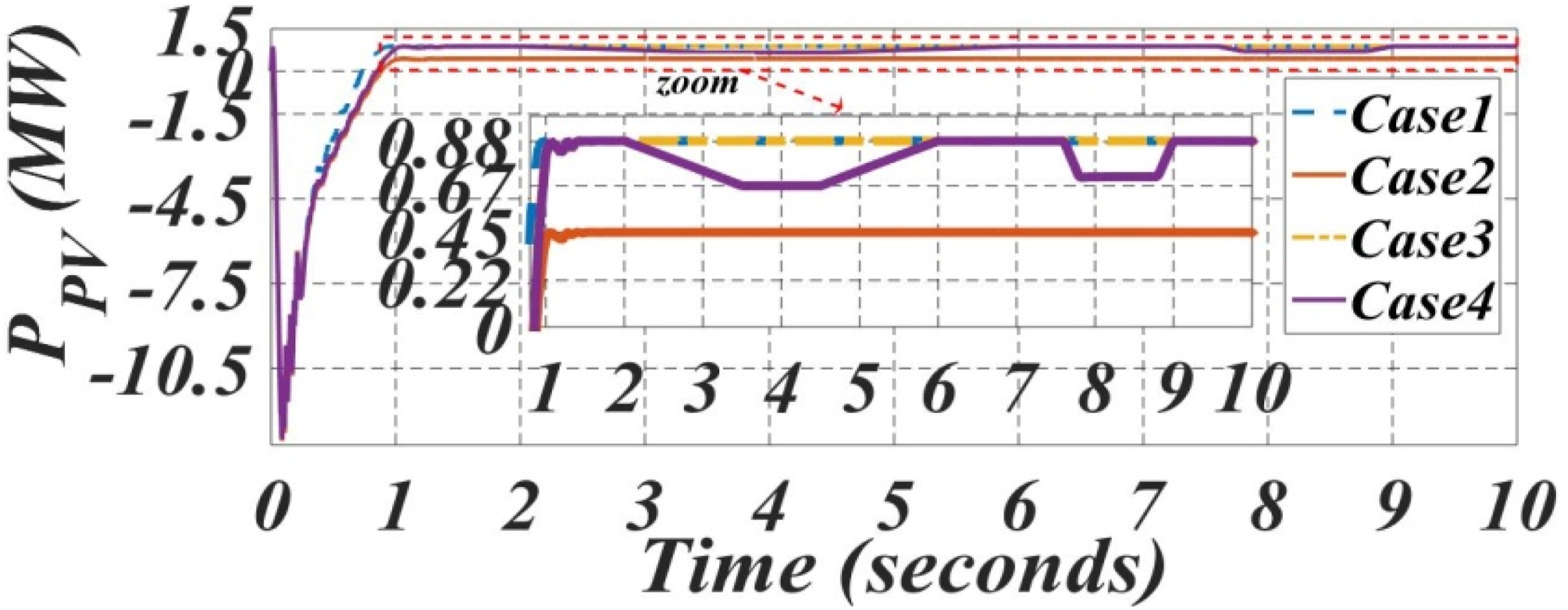
shown in Figure 19 over a 10 s time interval. PV current. PV power injected into the DC bus.
In all examined cases, the PV system exhibits a rapid transient response during the initial second, indicating prompt adaptation to changing system conditions or environmental inputs. This quick stabilization is a critical attribute in grid-connected hybrid renewable systems, as it minimizes disturbances and supports voltage and frequency regulation at the PCC (EL Sayed et al., 2025; EL Sayed, 2024).
Among the four scenarios, Cases 1 and 3 demonstrate superior steady-state performance, achieving peak current values around 770A and delivering approximately 0.88 MW of power. These results suggest that the PV subsystem benefits from stable interfacing with both the grid and the wind subsystem and that the MPPT strategy employed is highly efficient. The robustness and tracking accuracy of the control algorithm implemented in these cases enable consistent power extraction near the maximum power point.
Case 4 presents a more complex behavior. While its initial performance is comparable to that of Cases 1 and 3, with similar power output levels, noticeable drops in current and power occur between 2–6 s and again from 7.5–9 s. These fluctuations are attributed to variations in solar irradiance. Although the output temporarily degrades, the system successfully recovers, reflecting the responsiveness and effectiveness of the MPPT controller in adapting to dynamic environmental conditions.
Conversely, case 2 records the lowest output values, with a current of around 400A and a power output of approximately 0.45 MW. This behavior corresponds to a scenario designed to prioritize wind energy generation, implying limited utilization of the PV array’s capacity, potentially due to low irradiance. Although the system remains stable, the reduced PV contribution constrains the overall performance and productivity of the hybrid system.
Overall, the comparative results underline the significance of coordinated control in hybrid PV/Wind systems. Efficient MPPT implementation, dynamic interaction between sources, and proper sizing and tuning of converters are essential to ensure stable and optimal performance. In particular, the synchronization between the PV array and the DFIG wind subsystem plays a pivotal role in maintaining grid stability and maximizing renewable energy harvesting.
DC-link voltage
Figure 20 presents DC-link voltage behavior with a zoomed view from 2 to 10 s, which highlights the steady-state performance of the grid-connected hybrid DFIG/PV system interfaced via a back-to-back converter. The DC-link voltage V
dc
behavior of the grid-connected hybrid DFIG/PV system was evaluated under four distinct scenarios, reflecting various combinations of solar irradiance and wind speed. The initial transient phase (0–2 s) exhibits a rapid rise in V
dc
, followed by a settling period as the back-to-back converter regulates the power flow. All cases converge toward the nominal 1150 V, yet show varying transient characteristics. Case 1 experiences the highest overshoot due to a strong PV surge, while Case 2 shows the smoothest and fastest settling response, thanks to a stable power supply from the wind turbine. DC bus voltage.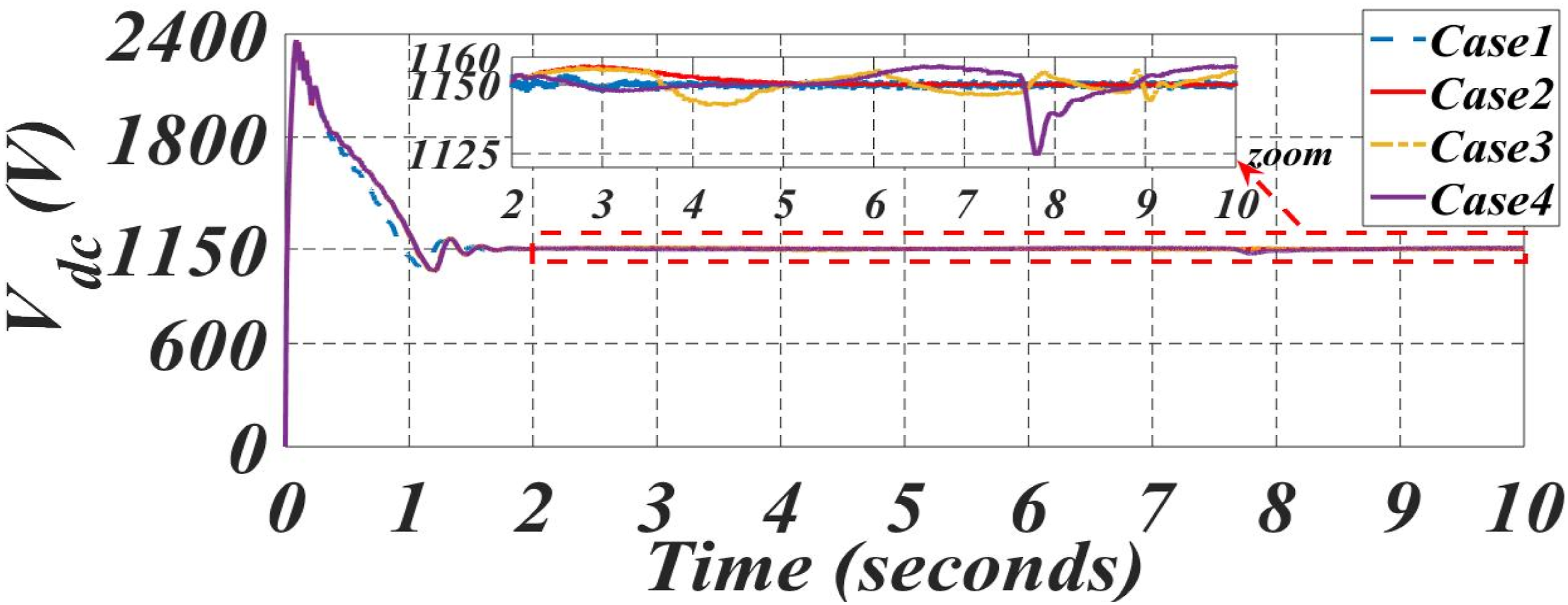
In the steady-state period (2–10 s), highlighted in the zoomed-in view, Case 2 maintains excellent voltage regulation with minimal ripple, indicating strong control performance under dominant wind contribution. Case 1 also performs well, with mild oscillations related to solar variability. Case 3 reveals more pronounced oscillations, likely caused by the dynamic interaction of the hybrid sources and the DFIG operating near synchronous speed. In contrast, Case 4 shows the most challenging behavior, with a significant voltage dip observed around 7.8 s, followed by a slower recovery. This illustrates the strain placed on the converter control system during fast-changing hybrid generation scenarios.
The DC-link voltage remained stable despite fluctuations in generation, as depicted in Figure 20. In conclusion, the hybrid DFIG/PV system effectively maintains DC-link voltage regulation across all cases. However, Case 2 demonstrates the most stable dynamic and steady-state behavior, underscoring the value of consistent wind power in hybrid renewable configurations. On the other hand, Case 4 highlights the need for more adaptive or predictive control strategies to handle rapid fluctuations in energy input.
Across all scenarios, the coordinated operation of the DC bus capacitor, the RSC, and the GSC is essential for maintaining voltage regulation, reducing fluctuations, and supporting grid stability. These components collectively enhance the system’s energy conversion efficiency and reinforce its ability to operate both autonomously and in grid-connected modes.
Power output and efficiency
The simulation results illustrated in the figures demonstrate the coordinated behavior of the proposed system under varying operating conditions. Figure 21 presents the DFIG slip profile, clearly showing transitions between operational modes. Figures 22 and 23 display the power curves of the stator and the GSC, respectively. Together, these results highlight the system’s ability to regulate and maintain stable power injection, offering insights into its dynamic performance and energy management efficiency. DFIG slip. Stator power injected into the grid. GSC-out power injected into the grid.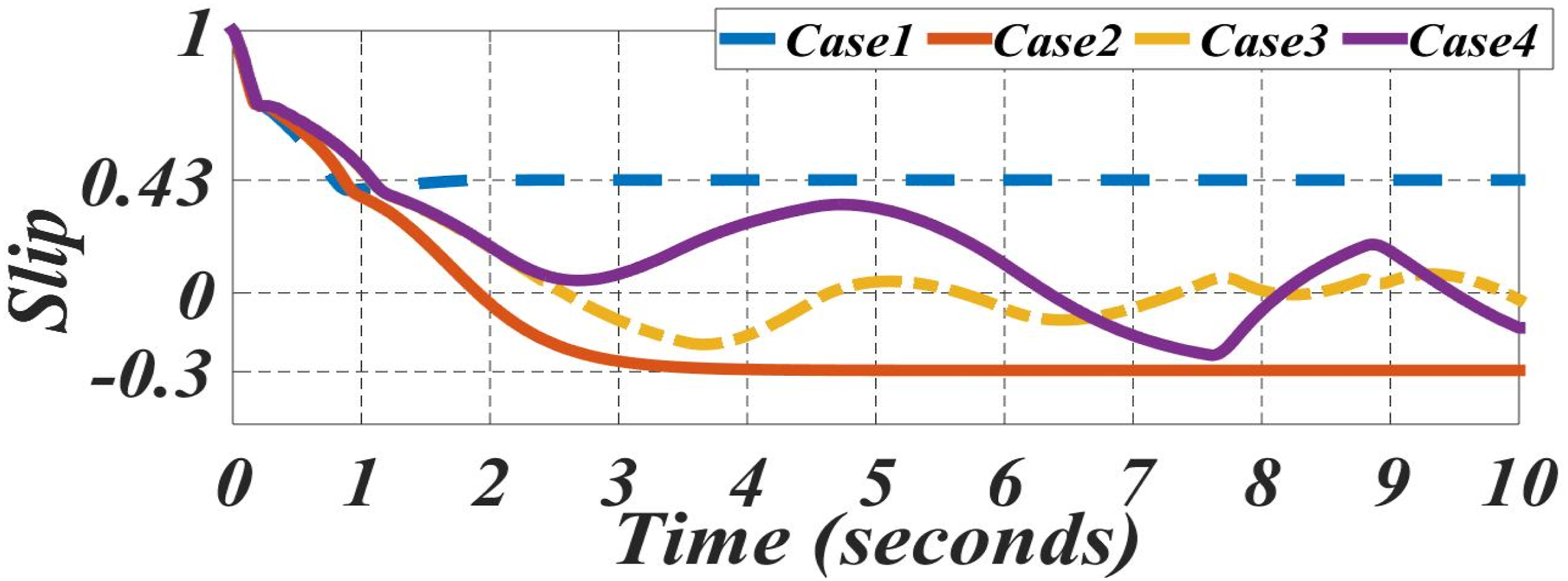
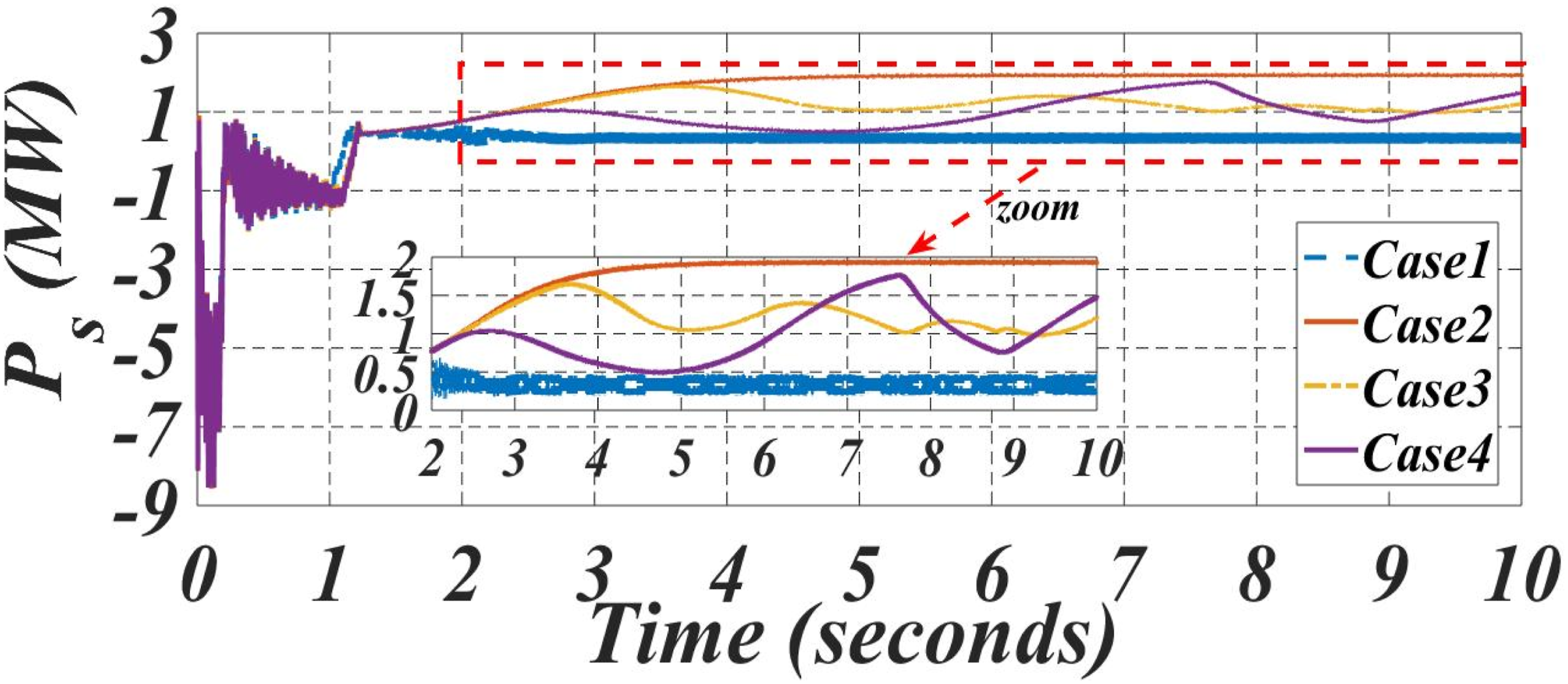

In Scenario 1, the wind turbine operates in the hypo-synchronous generator mode with a slip value of S = 0.43, meaning the turbine speed is below synchronous speed. This results in a positive slip, where the slip power is drawn from the grid and supplied to the rotor via the RSC. In this configuration, only the stator contributes real power to the grid. The PV array plays a supporting role by maintaining the DC bus voltage, while the GSC ensures controlled power injection. Figure 23 reveals an initial overshoot, which stabilizes within the first second, indicating effective damping characteristics and the system’s ability to suppress transient disturbances through capacitor filtering and converter modulation. Although power conversion efficiency is limited due to the unidirectional stator power flow, the system remains stable and compliant with grid requirements.
Scenario two explores the hyper-synchronous generator mode with a slip value of S = -0.3. Here, the turbine speed exceeds synchronous speed, resulting in both the stator and rotor injecting active power into the grid. This scenario produces the highest power output, as reflected by Figures 22 and 23, which exhibit increased amplitude and steady behavior. Despite a reduced contribution from the PV array, the DFIG takes a dominant role in power delivery. The RSC effectively manages active and reactive power flow, maintaining voltage and frequency stability. This configuration achieves maximum power conversion efficiency and demonstrates the system’s capacity for autonomous operation even under low solar irradiance conditions.
Scenario three represents coordinated operation between the wind and PV systems. In this mode, both energy sources contribute to the DC bus, improving overall energy availability and reducing reliance on the grid. The GSC functions as a multi-source converter, enabling seamless energy transfer. Figures 22 and 23 exhibit balanced and consistent behavior with minimal overshoot, confirming the synergistic effect of combining wind and solar energy. This scenario enhances total energy efficiency and promotes smoother power delivery, with the DC bus capacitor effectively mitigating short-term fluctuations.
Scenario four involves a dynamic transition between generator modes, allowing real-time switching between hypo-synchronous and hyper-synchronous modes in response to variations in wind speed. The initial stages of this scenario show more pronounced oscillations in Figures 22 and 23 due to the presence of rapid transients. Nevertheless, the system quickly regains stability thanks to advanced control strategies, including adaptive MPPT for the PV system, MPPT control for the wind turbine, and real-time inverter regulation. This scenario showcases the system’s flexibility and resilience in adapting to fluctuating external conditions, reinforcing its suitability for real-world deployment.
The efficiency of the proposed hybrid system was assessed across four operating scenarios. In Scenario 1 (hypo-synchronous mode), only the stator delivers power, yielding moderate output and an efficiency of approximately 80%, with the GSC stabilizing voltage and the PV maintaining the DC bus. Scenario 2 (hyper-synchronous mode) achieves the highest output and an efficiency of approximately 96%, as both stator and rotor inject active power, with stable GSC operation despite low PV input. Scenario three shows coordinated PV and wind contribution, resulting in balanced power, minimal overshoot, and an efficiency of approximately 92%, while reducing grid dependence. Scenario four features dynamic mode switching, with brief transients effectively managed by MPPT and inverter controls, maintaining an efficiency of around 85%. These results confirm the system’s flexibility and effectiveness under varying conditions.
Power quality and THD
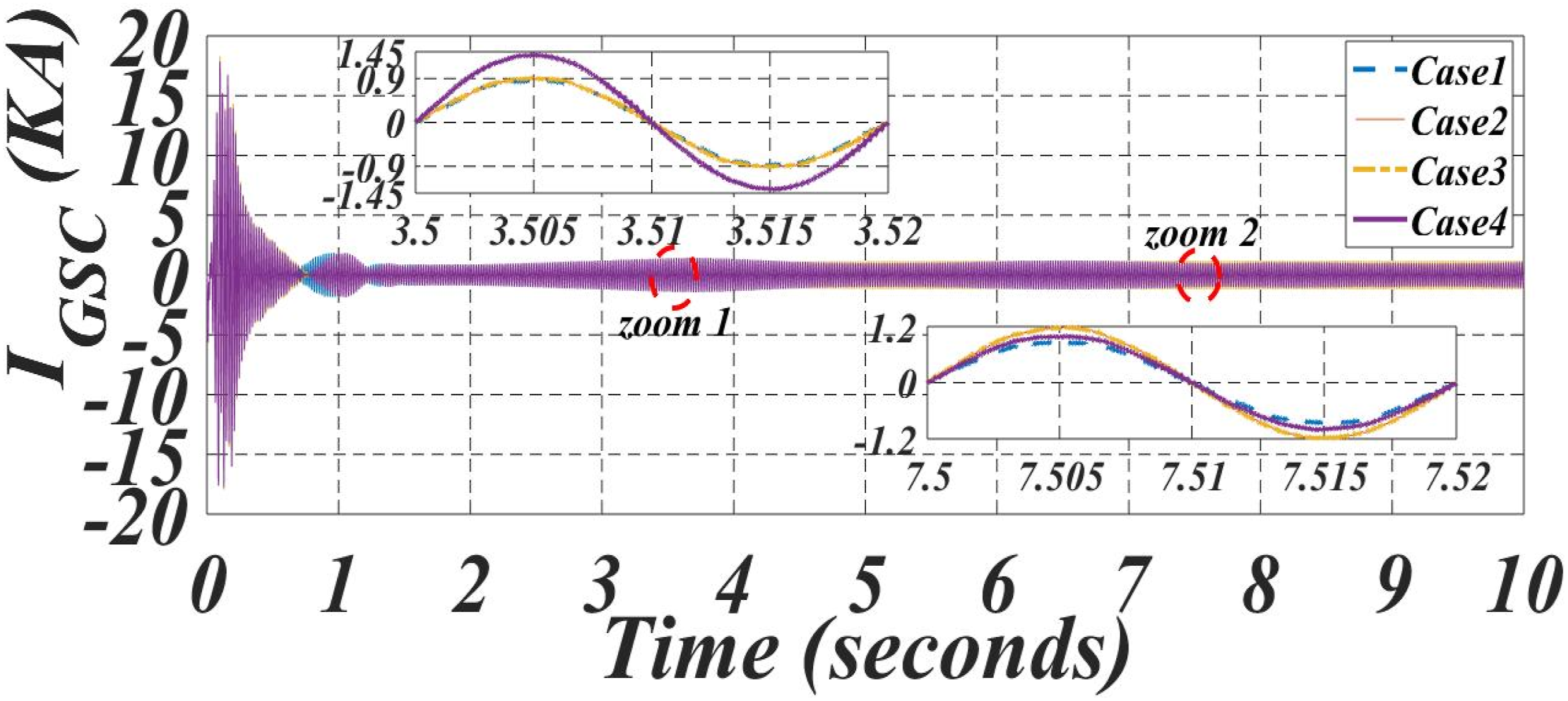
Ensuring high power quality is essential for the stable operation and effective grid integration of hybrid renewable energy systems (Hadi et al., 2023; Ahmed, 2024). The performance analysis is directly linked to the system’s behavior under four distinct scenarios characterized by varying solar irradiance and wind speed conditions. This evaluation focuses on examining the dynamic response of reactive power, the waveform integrity of output currents, and their harmonic content, following the standards outlined in IEEE Std 519-2022 (Std IEEE, 2022). The study relies on three principal figures. Figure 24, which illustrates the reactive power injected into the grid by the GSC, Figure 25 presents the output line currents under different operating conditions with detailed zoomed views, and Figure 26 highlights the THD levels of the GSC output currents across the four scenarios. GSC reactive power injected into the grid. GSC-out line current for each case. Line currents THD of GSC output: (a) Case 1, (b) Case 2, (c) Case 3, and (d) Case 4.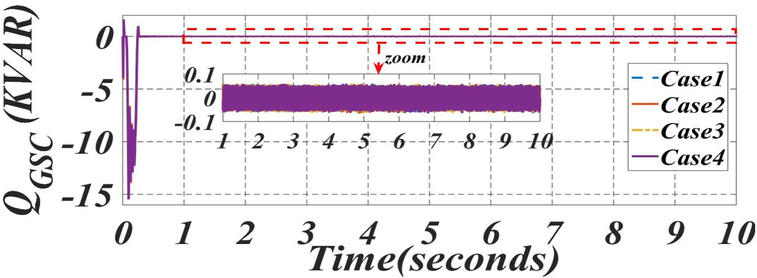

As shown in Figure 24, the reactive power injection exhibits an initial transient during the first second, followed by stabilization close to zero. This indicates that the GSC effectively manages reactive power disturbances and ensures a steady-state operation, which is crucial for maintaining grid voltage stability. It is observed that scenarios corresponding to higher renewable resource availability, such as Case 3, lead to quicker stabilization, reflecting improved control performance (F M A Hadi et al., 2023).
The analysis of the GSC output line currents, presented in Figure 25, focuses on two zoomed intervals, from 3.5 s to 3.52 s and from 7.5 s to 7.52 s. In both periods, the current waveforms demonstrate a stable periodicity of 0.02 s, corresponding to the grid frequency of 50 Hz, confirming precise synchronization with the network. Although the waveforms generally appear sinusoidal, slight distortions are noticeable, particularly under Scenario 4, where rapid fluctuations in environmental conditions cause dynamic transitions between hypo-synchronous and hyper-synchronous modes. These distortions are less significant in Scenarios 1 and 2, where either solar or wind predominates, leading to more stable current waveforms.
Further confirmation of waveform quality is provided by the THD analysis in Figure 26. In Case 1, associated with Scenario 1, the fundamental current reaches 881.3 A with a THD of 3.06%. In Case 2, corresponding to Scenario 2, the fundamental current increases to 1076A, and the THD decreases to 2.48%. Case 3, representing Scenario 3, shows a fundamental current of 1379A and a THD of 1.91%. Finally, in Case 4, linked to Scenario 4, the fundamental current peaks at 1489A, achieving the lowest THD of 1.62%.
This clear trend demonstrates that an increase in the fundamental current component is associated with a reduction in harmonic distortion, thus enhancing power quality. Moreover, it is observed that in Case 3, the THD remains well below 3% for a maximum current of approximately 900A, whereas in Case 4, despite the dynamic environmental variations, the THD remains within acceptable limits at 4.24% with a maximum current of around 625A.
The combined evaluation of reactive power behavior, current waveform analysis, and harmonic distortion measurement confirms that the proposed PV/wind hybrid renewable energy conversion system achieves robust performance across varying environmental conditions. The GSC ensures efficient reactive power regulation and maintains excellent harmonic standards, validating the system’s adaptability and compliance with IEEE Std 519-2022 requirements under operating scenarios (Std IEEE, 2022; Hadi et al., 2023).
To further assess power quality, specific harmonic orders were analyzed, focusing on the 5th (250 Hz) and 7th (350 Hz) components of the GSC output currents. Across the four scenarios, these harmonics remained within IEEE Std 519-2022 limits (Std IEEE, 2022), confirming effective harmonic mitigation. The active front-end RSC combined with the SRF-controlled GSC ensures sinusoidal current waveforms and stabilizes the DC-link voltage. To further reduce these dominant harmonics, passive LC filters tuned to the 5th and 7th orders were implemented at the GSC output. These filters effectively attenuate the targeted harmonic frequencies without affecting the fundamental, complementing the natural suppression provided by PWM modulation. Additional mitigation strategies, such as optimized PWM switching and DC-link filtering, further suppress residual harmonics. Correlation with DFIG mechanical parameters shows that rotor dynamics influence harmonic behavior and overall power quality, highlighting the system’s capability to maintain robust electrical performance even under varying mechanical operating conditions.
Voltage and frequency stability
As illustrated in Figure 27, which presents the voltage waveform along with a zoomed-in segment, the system consistently maintains a balanced and sinusoidal three-phase voltage profile throughout the entire simulation period. The waveform exhibits no significant distortion or asymmetry, indicating effective voltage regulation at the PCC (EL Sayed et al., 2025; EL Sayed et al., 2024). To examine waveform quality in more detail, Figure 27 includes a zoomed-in view of the output phase voltages around the 9-s mark. This segment clearly shows one complete period between nine and 9.02 seconds, thereby confirming a stable fundamental frequency of 50 Hz. The three-phase voltages (V
a
, V
b
, V
c
) appear well balanced in amplitude and accurately spaced by 120 electrical degrees, validating the converter’s performance in maintaining waveform symmetry and avoiding unbalanced or distorted conditions. These results comply with IEEE Std 519-2022, which sets harmonic and waveform distortion limits for grid-connected systems. Three-phase grid voltage (phase to phase).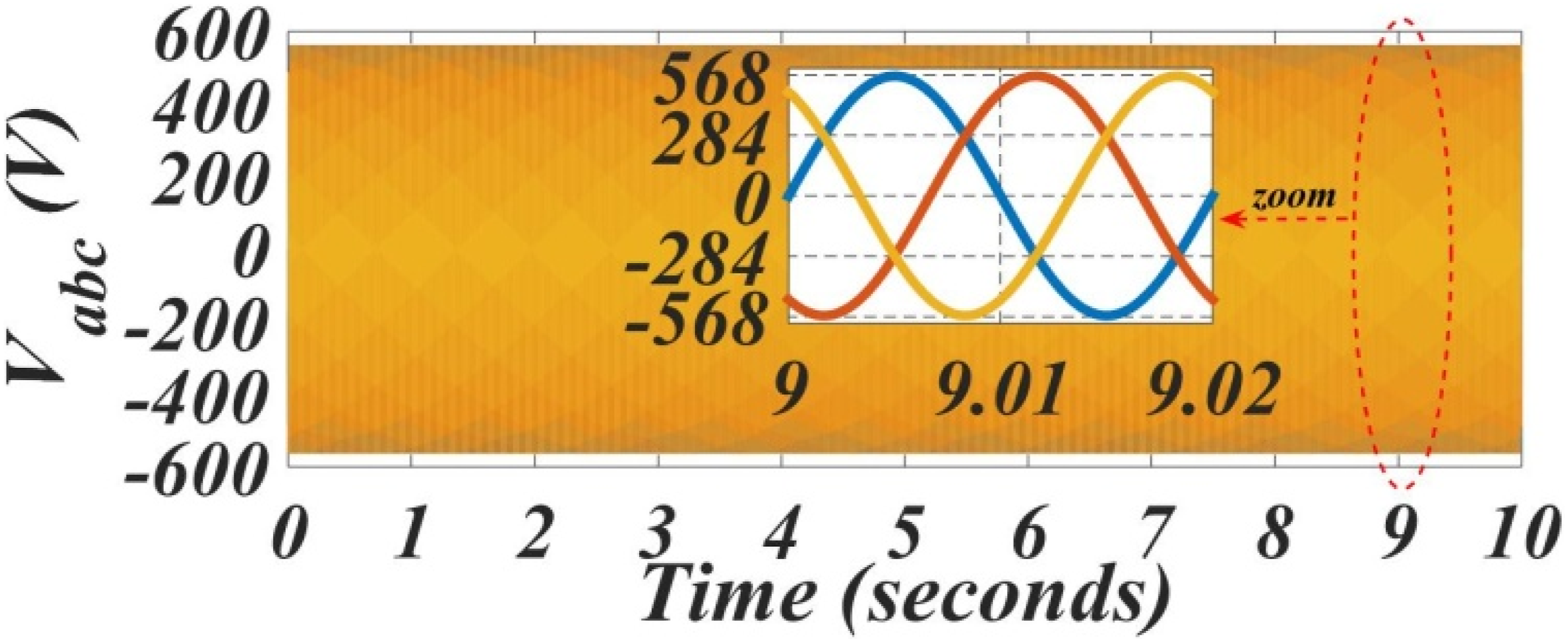
This voltage stability is achieved despite the variable nature of the input sources. The use of two dedicated MPPT techniques ensures optimal power extraction while stabilizing the DC voltage. The control strategy successfully decouples the fluctuations from the renewable sources, preventing them from propagating into the grid interface.
The combined converter topology enhances the system’s dynamic response, allowing for rapid compensation during transients. This ensures that both voltage magnitude and frequency remain within acceptable operational limits, satisfying the requirements of IEEE Std 519-2022 for grid-connected systems (Std IEEE, 2022; F M A Hadi et al., 2023).
In summary, the simulation results validate the system’s capability to maintain voltage and frequency stability, deliver clean sinusoidal waveforms, and ensure consistent power quality under varying operating conditions, making it well-suited for modern smart grid integration.
Conclusion
This study presents a comprehensive and efficient approach to hybrid renewable energy generation through the integration of PV and wind based on DFIG. The research highlights several key advancements, including the implementation of a simplified single-stage inverter topology, the application of SRF control for power quality enhancement, and the use of MPPT algorithms to ensure optimal energy harvesting from both renewable sources. One of the major strengths of the proposed system is its ability to maintain voltage and frequency stability across the DC and AC sides of the system, even under highly dynamic conditions such as changes in solar irradiance and wind speed.
The simulation results demonstrate that the hybrid system can effectively reduce voltage fluctuations, maintain DC-link stability, and deliver high-quality sinusoidal current to the grid with low total harmonic distortion. Furthermore, by minimizing the number of control loops and relying on robust semiconductors like IGBTs, the system achieves reduced complexity and lower maintenance costs, making it a practical solution for real-world deployment.
It is acknowledged, however, that the present study is limited to simulation-based validation. While this approach provides valuable insights into the system’s dynamic performance and control effectiveness, experimental validation (such as hardware-in-the-loop or laboratory-scale prototyping) would further strengthen the practical applicability of the findings. This limitation will be addressed in future work, where real-time hardware implementation and testing will be conducted to validate the proposed control strategies under realistic operating conditions. Moreover, additional investigations will focus on scalability challenges and resilience under extreme weather disturbances, such as rapid wind gusts and partial shading of PV arrays. In such cases, the application of intelligent optimization techniques, such as Particle Swarm Optimization (PSO) or Grey Wolf Optimizer (GWO), will be explored not only to improve maximum power point tracking accuracy when multiple local maxima exist under partial shading but also to ensure faster dynamic adaptation and stable control during abrupt wind variations. Furthermore, a hybrid control strategy that combines indirect speed-based MPPT with direct aerodynamic regulation through blade pitch angle adjustment will be considered to enhance system stability and maximize energy capture under highly variable wind conditions.
This research contributes meaningfully to the field of renewable energy by offering a scalable and technically sound system design that not only improves energy efficiency but also enhances the reliability and profitability of grid-connected renewable energy installations. Future work may include developing real-time hardware applications and integrating energy storage systems to enhance system resilience.
Footnotes
Funding
The authors received no financial support for the research, authorship, and/or publication of this article.
Declaration of conflicting interests
The authors declared no potential conflicts of interest with respect to the research, authorship, and/or publication of this article.
Data Availability Statement
Data will be made available on request.