
Abstract
This study proposes an innovative technique for energy management in hybrid microgrid systems using intelligent agent-based control approach. The hybrid microgrid architecture integrates multiple distributed energy resources, including wind turbines and photovoltaic arrays, to enhance overall operational efficiency. A lithium-ion battery energy storage system is incorporated to ensure system stability, while proton exchange membrane fuel cells (PEMFC) function as a reliable backup mechanism to mitigate power outages and improve system resilience. The deployment of intelligent agents facilitates the optimal coordination and management of energy generation and storage components, enabling seamless and adaptive system operation. To evaluate the efficacy of the proposed approach, a comprehensive simulation model was developed in Matlab/Simulink, incorporating realistic load profiles and meteorological conditions. The simulation results demonstrate the robustness and precision of the multi-agent Energy Management System (EMS) in regulating DC bus voltage, maintaining AC bus frequency stability, and optimizing power flow throughout the microgrid infrastructure.
Introduction
In recent years, microgrids have gained significant popularity due to their ability to integrate a number of renewable energy sources, including solar and wind energy sources. This integration is executed with exceptional reliability and efficiency by microgrids (Hirsch et al., 2018). The rapid growth and pervasive use of microgrids are a result of the widespread use of renewable energy sources on a global scale. A microgrid is a decentralized electrical network that supplies power to a specific region at low or medium voltage levels. The grid is distinguished by its numerous distributed energy sources, energy storage devices, and diverse power requirements. These components collectively function to establish the grid as an autonomous and self-sustaining energy system (Souza and Freitas, 2022).
Microgrids are highly adaptable, capable of functioning effectively in both grid-connected and islanded modes. Additionally, this adaptability ensures exceptional dependability, particularly in the event that the primary grid is unavailable. According to the voltage of the interconnection, microgrids can be classified as AC or DC systems. However, as opposed to alternating current (AC) systems, direct current (DC) microgrids offer a variety of benefits, including improved efficiency, reliability, and robustness, as well as fewer power conversion steps. In addition, DC systems enable the integration of modern electrical demands, including LED illumination, data centers, and electric vehicles, as well as renewable energy sources and energy storage technologies. The absence of a need for synchronization in DC microgrids, reduced skin effect, and enhanced power transfer capabilities make them a versatile and high-performance option for modern energy solutions (Charalambous et al., 2023).
The concept of DC microgrids has garnered significant interest in the current body of literature. Nevertheless, research continues on the performance of hybrid AC/DC distribution systems in building contexts. This study aims to evaluate the overall impact of introducing a hybrid AC/DC distribution system along with an energy storage system to address the existing research gap (Sinha and Bajpai, 2020).
Academic discourse extensively acknowledges the inherent variability of renewable energy sources, such as wind and photovoltaic systems. This variability can induce undesirable oscillations in power generation (Ghoniem et al., 2023), affecting the DC bus voltage and the system’s frequency. Despite the notable energy density of battery energy storage, additional measures are necessary to effectively meet peak load requirements. According to Ghoniem et al. (2023), employing energy storage with high-power density improves the efficiency of stand-alone renewable power systems. The use of regulated converters in high-power density systems is of utmost importance to extend the lifespan of energy storage systems and ensure a reliable and consistent power supply (Cui et al., 2022).
In order to ensure a consistent and uninterrupted supply of electrical energy, it is imperative to conduct a thorough investigation utilizing a dependable source. Recently, fuel cell devices have emerged as a viable alternative to diesel generators. The primary reason for this is the numerous issues that are associated with diesel generators, such as their inability to adapt to fluctuations in load demands, elevated maintenance expenditures, and carbon dioxide emissions (Tariq et al., 2023). A compelling research subject, the integration of proton exchange membrane fuel cells (PEMFC) into microgrid applications and electric vehicles (EVs) has been extensively examined and identified as possessing numerous substantial advantages, such as rapid load reactivity, exceptional efficiency, versatility in fuel usage, and the capacity to produce modular output (Lu et al., 2022). In order to establish autonomous microgrids, it is imperative to establish an effective Energy Management System (EMS). The EMS is indispensable for the efficient transmission of power between energy storage systems, sources, and loads, thereby satisfying demand while also adhering to the constraints established by the energy storage systems. In addition, the energy management system incorporates the pursuit of optimization objectives, such as the improvement of equipment durability and the reduction of operational expenses for microgrids, which makes the research on EMS both captivating and constantly evolving.
Backup power supply systems are essential as they deliver electricity in the event of a primary power failure. A fuel cell/electrolyzer combination is an excellent option for backup power due to its efficient on-demand hydrogen production capabilities. This strategy may ensure the continuity of power during emergencies and outages. This integrated functionality facilitates the identification and utilization of a backup power source (Karimov, 2020). Various types of microgrids and energy management systems have been developed to enhance the efficiency, reliability, and longevity of EMS inside microgrids.
Several studies have examined DC microgrids with PV/battery configurations, analyzing energy-management strategies and their impact on DC-bus stability and power sharing (Alidrissi et al., 2021; Arabshahi et al., 2022; Elmorshedy et al., 2023; Fotopoulou et al., 2021). These studies investigate energy management solutions across various distributed cooling and monitoring groups to eliminate the necessity for backup units. In addition, research has focused on reducing capital expenses and exploring different topologies of microgrids, including both independent and interconnected systems, using PV/battery technologies.
Ref (Kulkarni and Gaonkar, 2021) presents a droop approach based on virtual impedance control for islanded microgrids. The improved adaptive PID controller introduced in Ref (Siddique et al., 2019) aims to improve voltage and current regulation in an islanded microgrid. Ref (Suresh et al., 2021) investigates the application of fractional order calculus to enhance the performance of PI controllers in microgrid operation, allowing for increased degrees of freedom.
Energy management systems have included fuzzy logic methodologies. In Kalaiyarasan and Singaravelu (2024), a fuzzy logic controller based on voltage and frequency regulation to enhance power distribution efficiency among various system components is proposed. The authors in Ibrahim et al. (2023) present a fuzzy logic technique for energy management in microgrid that determines the appropriate operational mode by analyzing real-time data. The authors in Fathy et al. (2022) present an optimal adaptive fuzzy logic methodology that effectively harnesses energy from both distributed generation units and the main grid to adjust its parameters.
The authors in Heidary et al. (2023) propose a decentralized control technique for DC microgrids based on clusters of nanogrids. The architecture comprises clusters of nanogrids, typically residences, that operate independently while cooperating and exchanging resources within the community. An adaptive I-V droop method facilitates synchronized power distribution among these participating nanogrids. This approach depends on local measurements to ascertain the charge and condition of the DC bus voltage. A study in Sahoo et al. (2019) investigates an autonomous microgrid and energy management system that incorporates a Cooperative Adaptive Droop approach. This system integrates photovoltaic and battery components to execute accurate microgrid voltage regulation.
Advanced control systems are very important for managing energy in a microgrid because they help solve problems that come up when generating, distributing, and using energy. The Multi-Agent System (MAS) is a really unusual idea that has gotten a lot of praise (Azeroual et al., 2022). By using a distributed control architecture, MAS makes it possible for autonomous agents to work together to make decisions, which improves the reliability and efficiency of microgrids (Paliwal et al., 2022). MAS is a decentralized control approach that depends on individuals making autonomous judgments. This enables autonomous groups to collaborate and manage their activities, ensuring operational efficiency. The implementation of MAS in microgrids has resulted in significant advancements, including enhanced system architecture, innovative dispatch algorithms, and improved coordination of dispersed generators. In Roslan et al. (2022), a MAS-based EMS for a DC microgrid regulates the DC-bus voltage via a state-flow diagram. Although the work does not compare or detail alternative EMS strategies, the MAS implementation demonstrates clear potential for microgrid energy management.
The implementation of MAS in microgrid management is an innovative approach to energy management, emphasizing efficiency, reliability, and flexibility. MASenhance effective communication and cooperation among distributed agents, allowing for the development of a versatile and adaptable energy management system that meets the complex requirements of modern microgrids. This methodology enhances the efficient integration of renewable energy sources while simultaneously improving the stability and performance of the microgrid, establishing MAS as a crucial technology for future energy management systems.
Recent research has emphasized advances in EMS for hybrid microgrids, particularly those that leverage the capabilities of MAS. In Azeroual et al. (2020), a MAS-based EMS is implemented using the Java Agent Development Framework (JADE). The system revealed how sensitive EMS performance is to communication restrictions by employing PI controllers. In contrast Benlahbib et al. (2020), investigates an EMS for a microgrid with PV, fuel cells, batteries, and supercapacitors, demonstrating the adaptability of modern EMS through an Adaptive Fractional Fuzzy Sliding Mode Control (AFFSMC) approach.
In Yu et al. (2023), researchers introduced a multi-agent supervisory control technique for an isolated DC microgrid, showcasing further innovation. This solution kept the average system voltage at the desired level by employing two power management strategies: optimal power distribution and equal power allocation. Similarly, the deployment of a decentralized MAS in Coelho et al. (2017) made it easier to incorporate demand-side activities, resulting in lower energy costs, greater energy efficiency, and improved energy supply security and stability.
Furthermore, the use of MAS has been shown to successfully regulate reactive power in distribution networks with renewable energy sources, hence improving dynamic voltage stability (Murray et al., 2021). This examination of several control systems demonstrates the advantages of the proposed MAS-based strategy for microgrid energy management. While classic methods, such as PID controllers and droop characteristics, are clear and easy to use, they are ineffective at dealing with some of the more complicated difficulties that arise in microgrid management. Modern approaches, on the other hand, are distinguished by their ability to improve microgrid performance while leveraging complexity. These sophisticated methods use extensive computations to determine and execute optimal settings, improving the efficiency of microgrid energy management.
This paper proposed an advanced energy management system based on MAS for a hybrid microgrid, leveraging the synergies between PV panels, wind turbines, Fuel Cells (FC), and battery energy storage. The main objective of this strategy is to efficiently address the current difficulties by simultaneously harmoniously achieving numerous important goals. Specifically, it controls the fuel cell’s power generation by considering the State of Charge (SoC) of the battery. Additionally, it guarantees that the hydrogen pressure is maintained at a level that effectively regulates the battery SoC within acceptable parameters. Furthermore, it ensures the stability of voltage and frequency control. The key contributions of this autonomous microgrid EMS are as follows: Introducing a novel energy management system with SoC deviation as a critical control parameter for a self-sufficient hybrid DC/AC microgrid system with a fuel cell backup for the battery. Developing intelligent control mechanisms that effectively coordinate the microgrid’s loads, ESS, and various energy sources. Maximizing energy utilization by optimizing power extraction from the principal sources. Minimizing hydrogen usage to optimize overall energy efficiency. Improving voltage quality within the microgrid for enhanced reliability and performance.
The paper is organized as follows: Modeling of Microgrid details the microgrid concept, describing each component. Discussion on the multi-agent system is provided in Multi-Agent System (MAS). Proposed Energy Management System (EMS) introduces the proposed EMS for the microgrid. Results and discussions are presented in Simulation Results and Discussion. Finally, Conclusion concludes the paper.
Modeling of microgrid
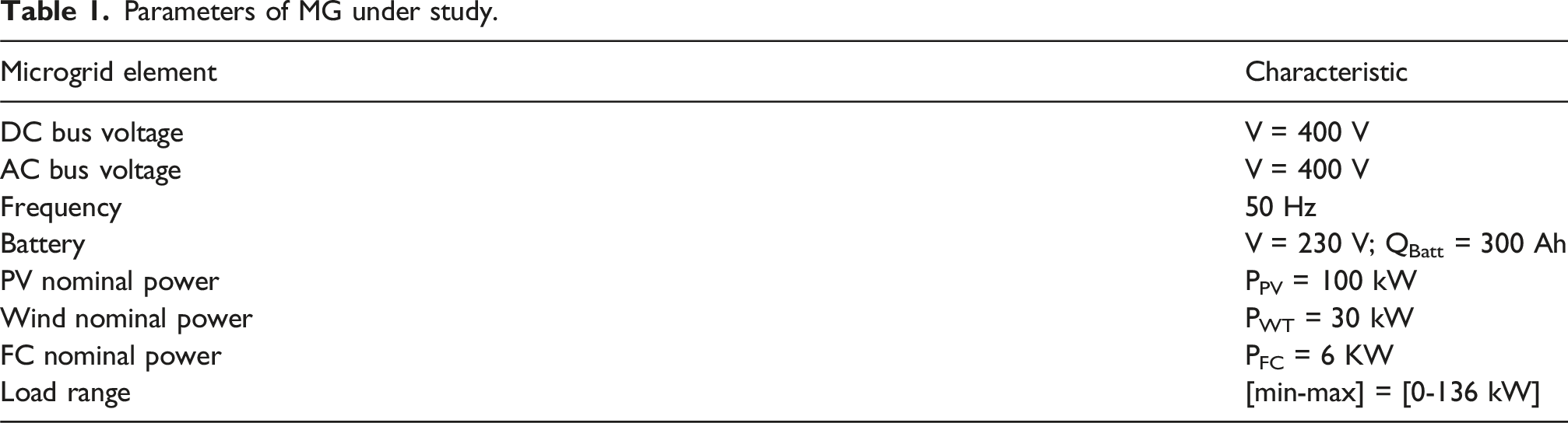
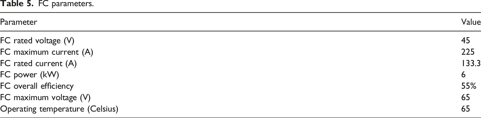
The configuration of proposed hybrid microgrid is shown in Figure 1. The primary element consists of a solar photovoltaic system, which has a total capacity of 100 kW and is interconnected by a DC/DC converter. Furthermore, the microgrid has a wind energy generator comprising three wind turbines. Each turbine is connected to a Permanent Magnet Synchronous Generator (PMSG) and has a power rating of 10 kW. The wind energy generator connects with the microgrid using a rectifier and a DC/DC converter, providing a cumulative power output of 30 kW. The FC is a secondary power source, providing a reliable, uninterrupted energy supply to mitigate power failures. Under typical circumstances, it generates a maximal power output of 6 kW. Microgrid schematic under study.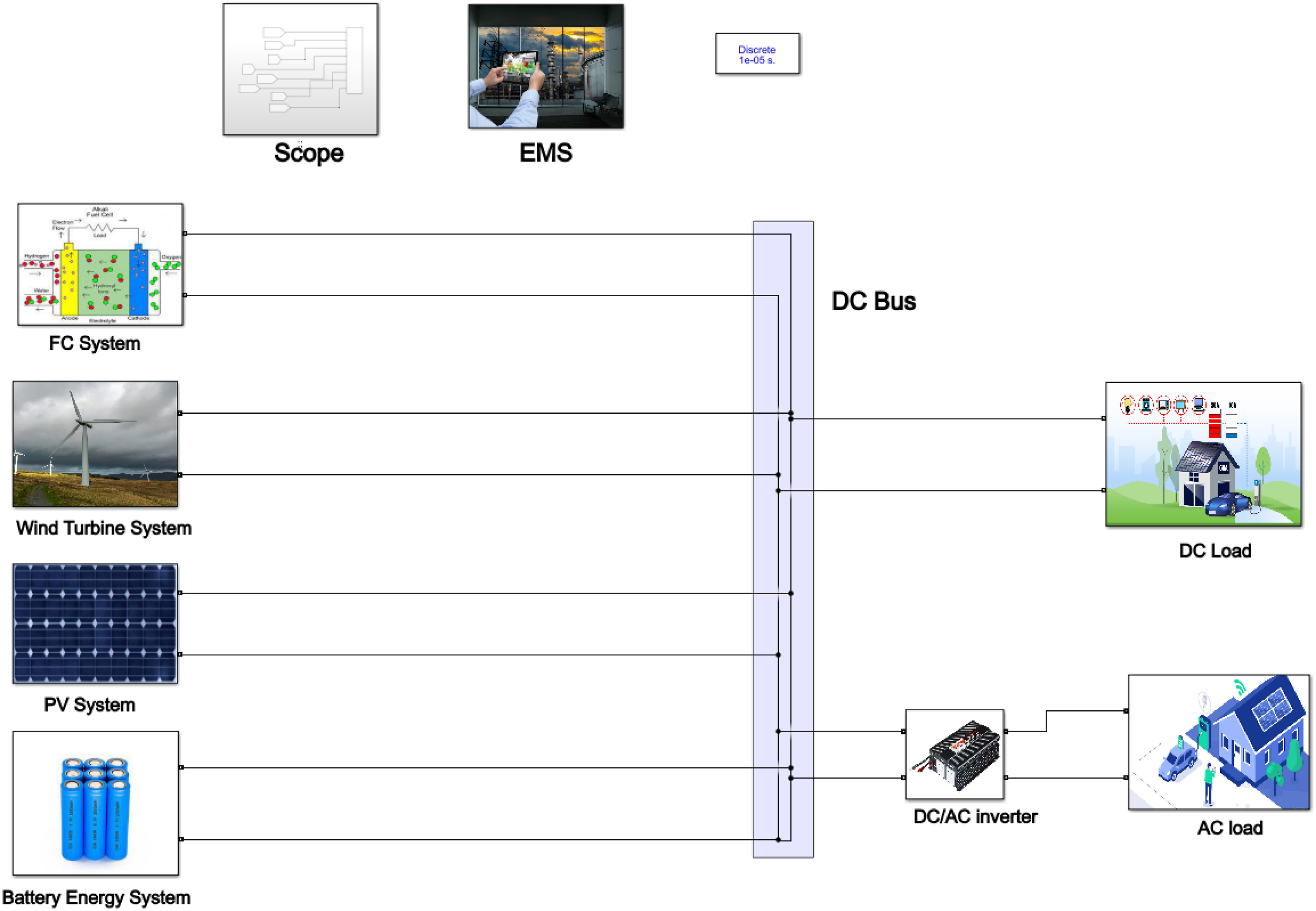
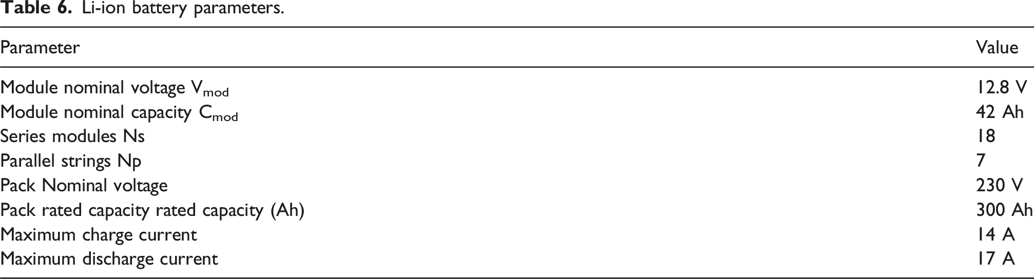
In addition, the microgrid incorporates a battery energy storage system consisting of lithium-ion batteries operating at a voltage of 230 V and with a capacity of 300 Ah. Distributed energy resources (DER) are regulated to function at their maximum power point tracking (MPPT). The energy storage system employs bidirectional DC/DC converters to regulate the voltage of the DC bus, ensuring it remains at a constant level of

Parameters of MG under study.
PV system
The microgrid’s photovoltaic system consists of PV arrays linked to the DC bus by a boost DC/DC converter. The boost converter regulates the voltage and power transfer between the PV arrays and the DC bus (Figure 2). This boost is based on the perturb and observe (P&O) algorithm MPPT control to optimize power output. The MPPT system uses the instantaneous photovoltaic voltage and current as inputs, generating a reference voltage corresponding to the maximum power point. PV system array featuring its MPPT control.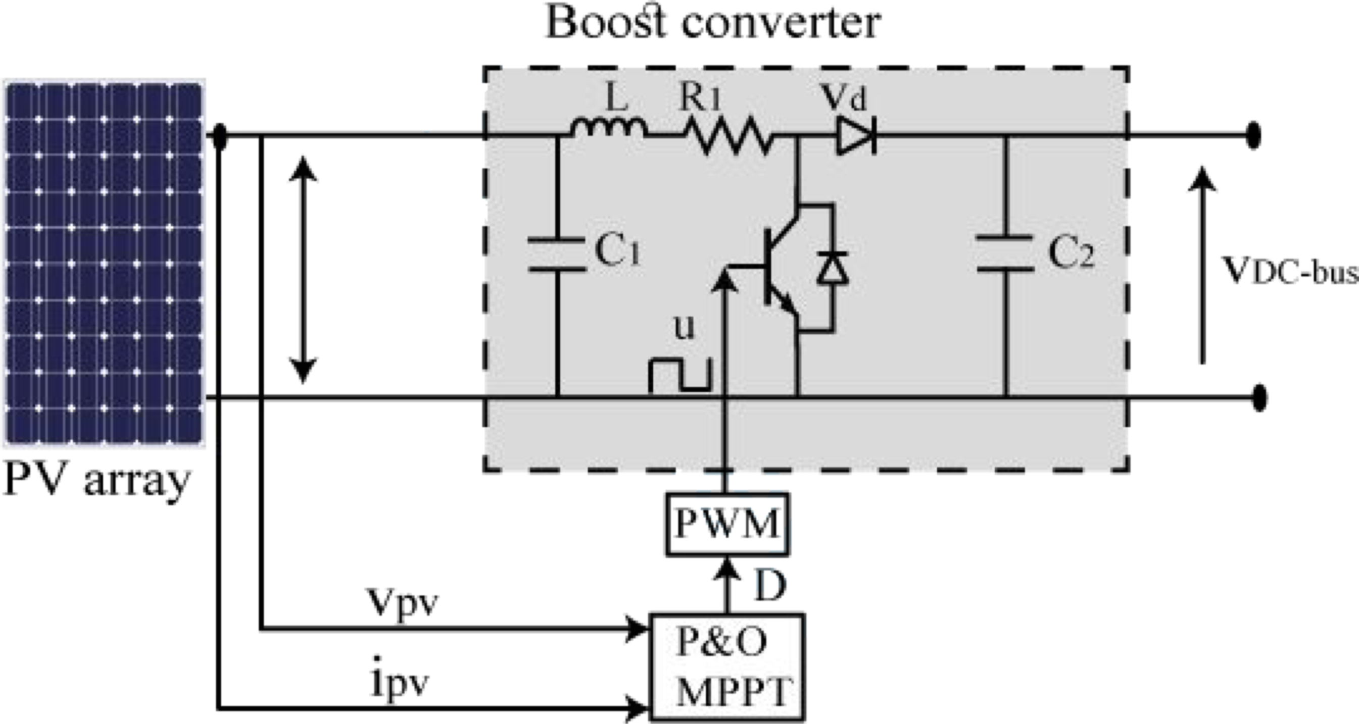
The output power (Ppv) of the PV module can be calculated by using the solar irradiance (Gt), the rated capacity of the PV module under standard test conditions (PPV_rated), the temperature coefficient (αt), the cell temperature at STC (TC_STC), and the ambient temperature (Tamb).
Following is the formula for calculating the module’s output power (Bukar et al., 2019): P
PV
is the output power of the PV system (W); P
PV
_
rated
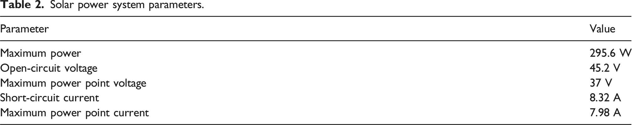
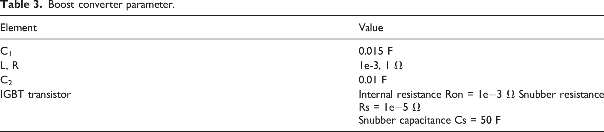
is the rated power of the PV module at standard test conditions (W); αt is the temperature coefficient of the PV module (1/°C); TC_STC is the cell temperature at normal test conditions (°C); Tamb is the ambient temperature (°C); Gt is the solar irradiance incident on the PV module ((W/m2); Gt_STC is the solar irradiance at standard test conditions (W/m2). Moreover, the solar power system parameters are in Tables 2 and 3 lists the DC–DC converter parameters. Solar power system parameters. Boost converter parameter.
Wind power system
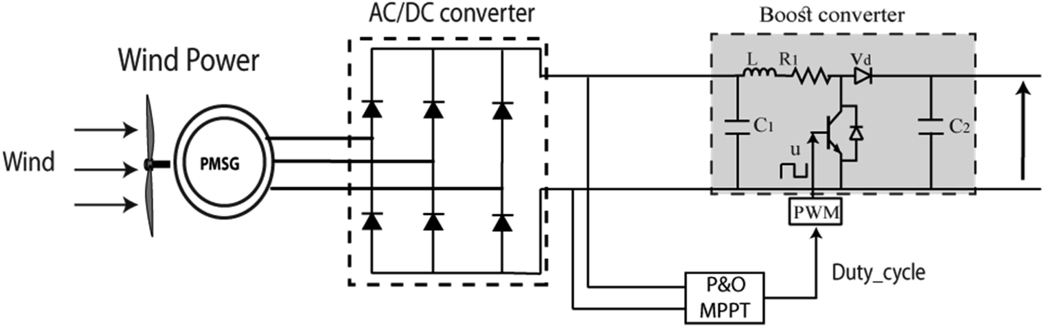
The proposed wind energy system consists of several components, as illustrated in Figure 3: A compact variable-speed wind turbine A permanent magnet synchronous generator (PMSG) An unregulated three-phase rectifier A DC/DC boost converter A DC link capacitor 3 wind turbines PMSG-based wind energy conversion system configuration with MPPT control.
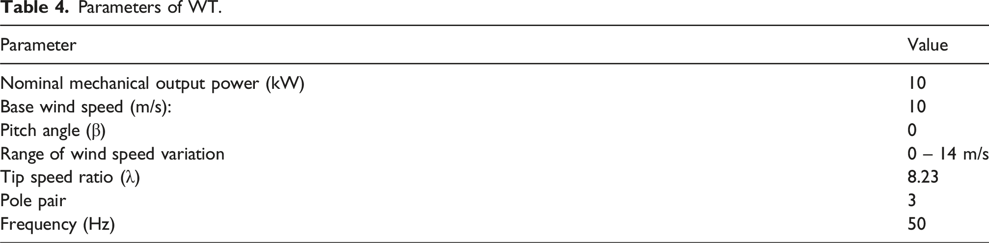
Parameters of WT.
The power (Pwind) generated by the wind turbine system can be calculated using equation (3) (Mehdi et al., 2023): P
wind
is the power generated by the wind turbine (W); ρ is the air density (kg/m3); A is the swept area of the wind turbine blades (m2); C
P
(λ, β) is the power coefficient, which expresses the relationship between the tip speed ratio λ and the pitch angle β; V is the wind speed (m/s).
FC modeling
The extant literature has investigated a range of operational behaviors of fuel cells. The literature study demonstrates that the Proton Exchange Membrane Fuel Cell (PEMFC) presents notable benefits compared to traditional fuel cell technologies (Maiti et al., 2022).
The PEMFC presents a range of advantages, such as its ability to initiate operations quickly, its notable adaptability, outstanding resistance to thermal fluctuations, and heightened safety standards. Several inputs, including pure methanol, formic acid, and hydrogen, power the selected fuel cell stack. PEMFC functions as an electrochemical conversion mechanism that directly transforms the chemical energy of the fuel into electrical power (Ondrejička et al., 2019). The determination of the output voltage of a single cell is established using in Dahale et al. (2017).
A fuel stack consists of “N” individual fuel cells. According to equation (4), the total voltage of the fuel stack (VT) is calculated by multiplying the total number of fuel cells by the voltage of each fuel cell (Vfc).


Double-layer charging can be accurately depicted by including an electric capacitance, abbreviated as Cdl, which is coupled in parallel with the components Ract and Rconc (Ghardash Khani, 2022), as shown in Figure 4. The voltage drops across the capacitance Cdl, denoted as Vdl, can be determined using equation (7) due to the given arrangement. FC electrical equivalent circuit.
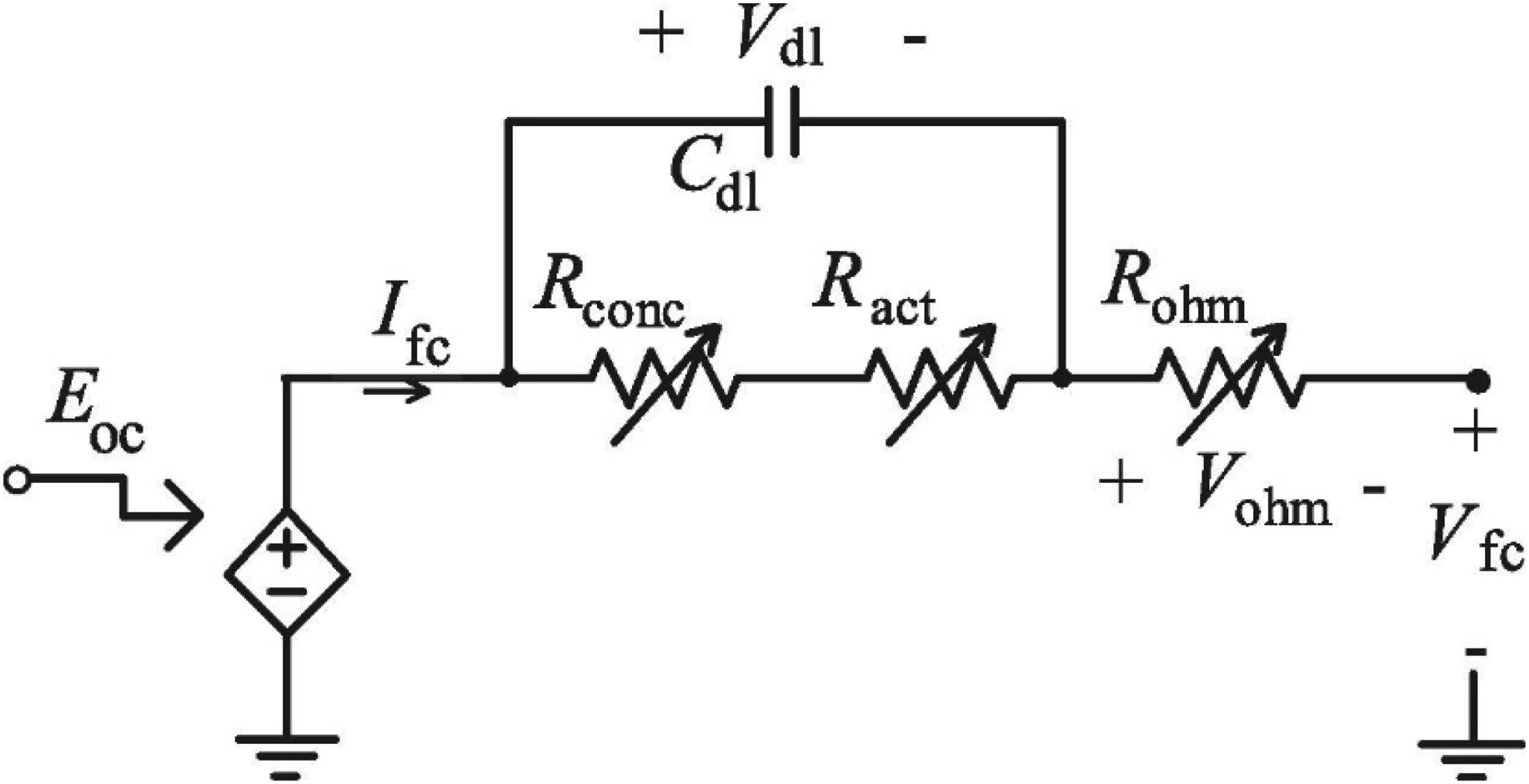
Figure 4 shows the incorporation of an electric transient model into a PEM fuel cell system. This integration utilizes an equivalent circuit model representing equations (4) and (5). Nonlinear components Rconc, Ract, and Rohm are used to simulate resistances. In addition, the fuel cell burden can be connected across the Vfc terminals. In equation (8), 
FC parameters.
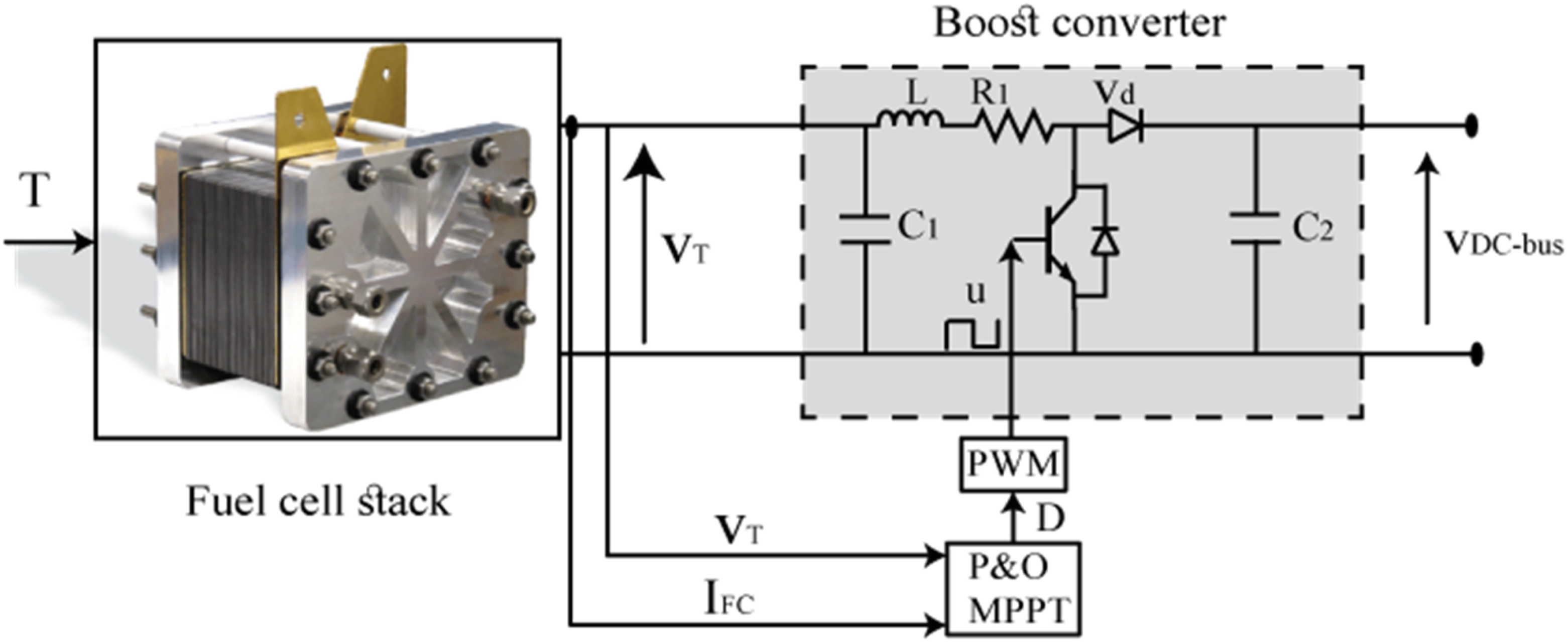
Schematic diagram of FC system with MPPT.
Battery modeling
In recent years, energy storage systems (ESS) have been significantly adopted to mitigate power fluctuations, compensate for the intermittent nature of renewable energy generation, and ensure a dependable and manageable energy supply. Battery energy storage is often regarded as the predominant choice among the diverse range of energy storage technologies now accessible. Battery energy storage systems are widely recognized for their exceptional energy density despite their comparatively limited output power capacity. This study primarily focuses on the utilization of lithium-ion battery-based energy storage systems. Generally, the battery is commonly depicted using a theoretical framework incorporating a voltage source and resistor coupled in series. This voltage source’s magnitude depends on the battery’s state of charge (SoC) (Dai et al., 2021).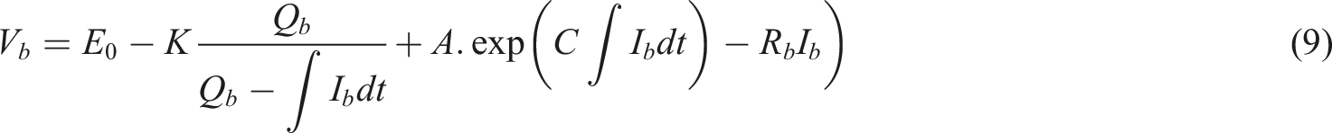
Vb indicates the voltage of battery, E0 represents the open-circuit voltage, Qb signifies the capacity of battery, Ib depicts the battery current, K refers to the polarization constant, A relates to the amplitude of the exponential zone, and C is the inverse of the exponential zone time constant.

Li-ion battery parameters.
Multi-agent system (MAS)
An Intelligent Agent (IA), is an autonomous entity that can acquire knowledge about its surroundings through sensors and, subsequently, take appropriate actions in response to this acquired information through actuators. The basic aim of IA is to effectively accomplish predetermined objectives via the utilization of intelligent decision-making processes and appropriate actions. An agent can be considered intelligent if it can effectively process data, utilize rules and algorithms, and interact with its environment and other agents. IAs exhibit varying behaviors and functionalities contingent upon the specific context within which they operate. Agents can make independent judgments, functioning without the requirement of a central controller or commander (Hagras et al., 2008). Agents have distinct behaviors and strive to accomplish predetermined goals by employing their resources, abilities, and services, as seen in Figure 6. Control levels within the microgrid environment.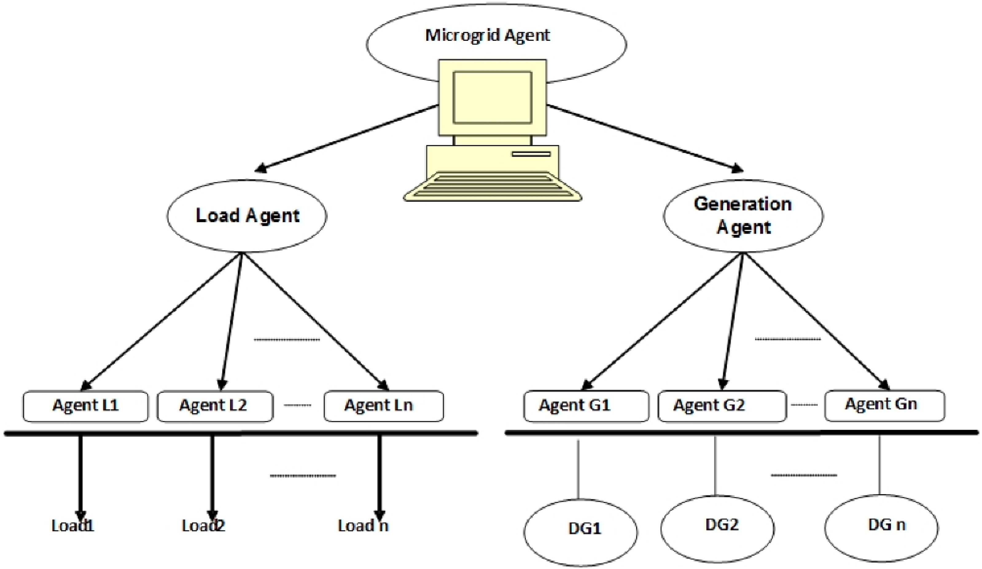
(a) Simple reflex agents rely on a predefined set of condition-action principles and make instantaneous decisions based on their current observations.
(b) Model-based reaction agents: These agents possess an internal model of their surroundings, allowing them to consider the broad picture when making decisions.
(c) Goal-oriented agents: These agents maintain a set of objectives and employ techniques such as planning and logical reasoning to achieve their desired outcomes. Individuals decide their course of action by considering their anticipated impact on their goals.
(d) Utility-based agents: These agents can evaluate the desirability of various actions and make decisions that maximize expected utility using utility functions. They consider both the desired outcomes and the consequences of their options.
Agents that possess the capacity to acquire knowledge can enhance their decision-making capabilities through the acquisition of new information over some time. Individuals modify their behavior through many learning mechanisms, including reinforcement-based learning and observational learning.
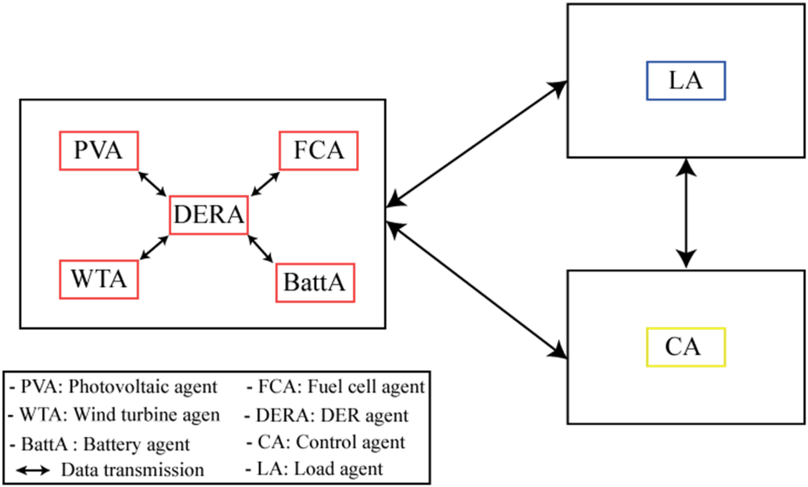
Each agent operates autonomously, with its role comprising a set of behaviors. The behaviors are categorized into three unique classifications based on their specific goals and objectives, as illustrated in Figure 7. DER agent: This agent is responsible for actively regulating the output power of distributed energy resources to ensure consistent frequency and voltage levels. The system analyses data, controls certain sources, and collaborates with other agents to determine the output power based on predefined control objectives. The data associated with this agent includes the unit’s name, power constraints (both minimum and maximum), and droop control gradients. Conversely, the variable data consists of both power settings and status information. The Photovoltaic agent (PVA) is an electric generator that utilizes photovoltaic technology to generate power. Its purpose is to receive and execute electric power demands from the microgrid controller. The Wind turbine agent (WTA) is an entity that adjusts its electric power output based on instructions from the microgrid controller, specifically tailored for wind power generators. The Battery Agent (BattA) oversees the DC bus and modulates the electric power output by instructions from the microgrid controller. The Fuel Cell Agent (FCA) is tasked with controlling the electrical power output of the fuel cell generator based on the instructions provided by the microgrid controller (EMS). The load agent is responsible for assessing data, managing specific loads, and negotiating with other agents to acquire suitable power levels. The control agent is designed to operate as an advisory agent and an energy management system (EMS). The primary objective of this system is to facilitate the coordinated administration of operational modes, ensuring the regulation of frequency and voltage on both DC and AC buses. Structures of proposed agents.
The EMS oversees the power regulation of individual DER units through the lower-level unit agent. At the same time, the higher-level coordinated control agent supervises the principle of AC voltage, DC voltage, and frequency.
Figure 8 illustrates a composite microgrid, combining both electrical and agent layers. These layers are interconnected through communication lines based on the MACSimJX interface (MultiAgent Control for Simulink application). The microgrid layers encompass producers, consumers, and distribution lines, simulated using Matlab/Simulink. In contrast, the computer layers exclusively comprise agents connected through telecommunication systems designed and manufactured using JADE. JADE and MATLAB/Simulink are employed on a single system to allow the agents in the MAS layer to gather data in the Simulink process layer. A crucial prerequisite is to build a real-time connection between JADE and MATLAB/Simulink to ease data interchange, enabling the MAS to control and make decisions effectively. MACSimJx: interconnection between MATLAB/Simulink and JADE.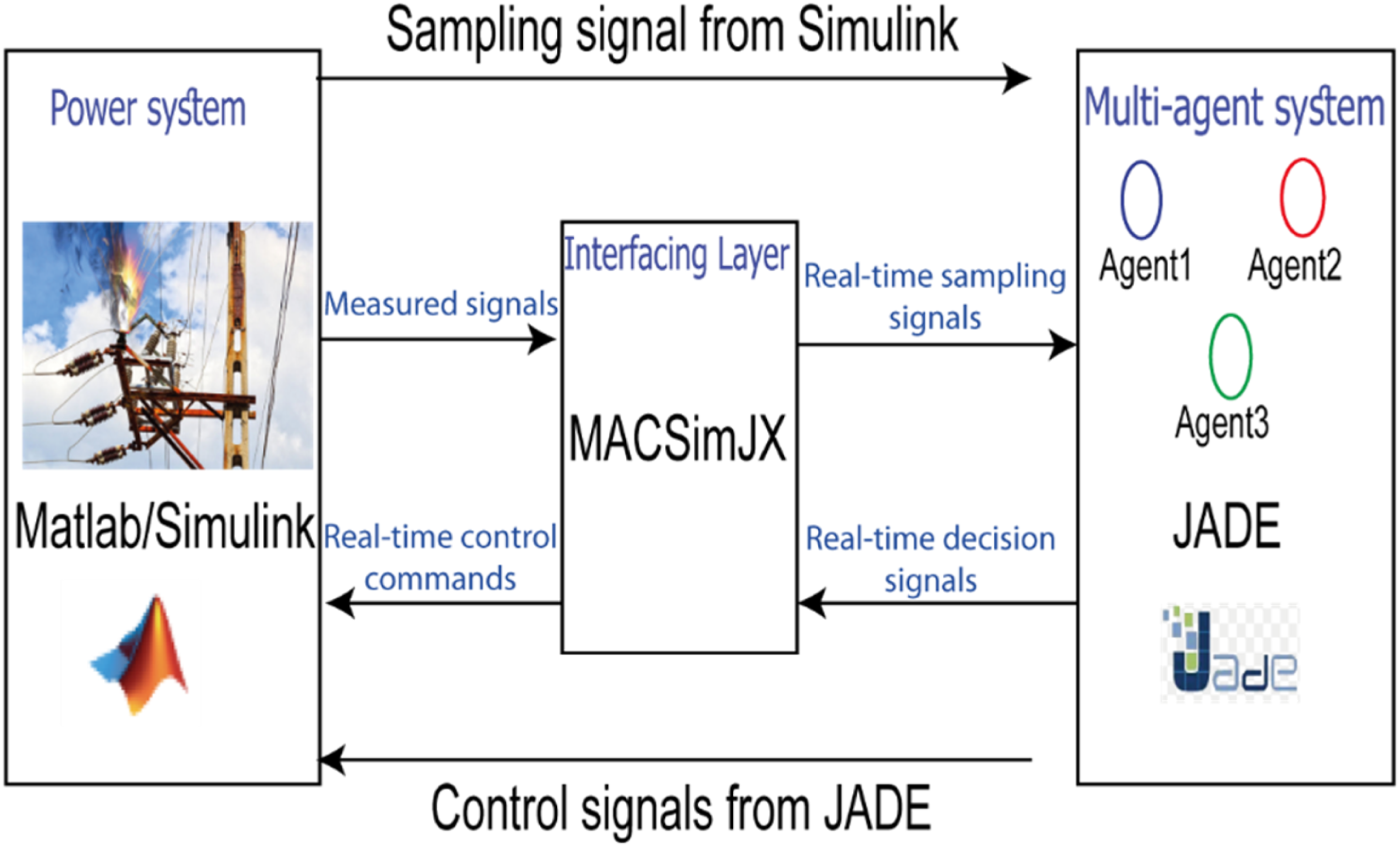
Proposed energy management system (EMS)
This paper focuses on efficiently utilizing various renewable energy sources, including PV, WT, fuel cells, and battery energy storage systems, to meet the load demand while ensuring optimal longevity and minimal hydrogen consumption. To achieve this goal, an energy management system scheme is proposed. In this context, an EMS employs a rule-based controller scheme that considers load power (Pload), DC bus voltage, and battery state of charge level. The schematic representation of the proposed EMS system is illustrated in Figure 9. Within the EMS framework, continuous monitoring of the battery SoC occurs, enabling optimal operating points for all energy sources. These calculations aim to keep the SoC within predefined limits while concurrently regulating the DC bus voltage to maintain it at the nominal value. Flowchart of proposed EMS.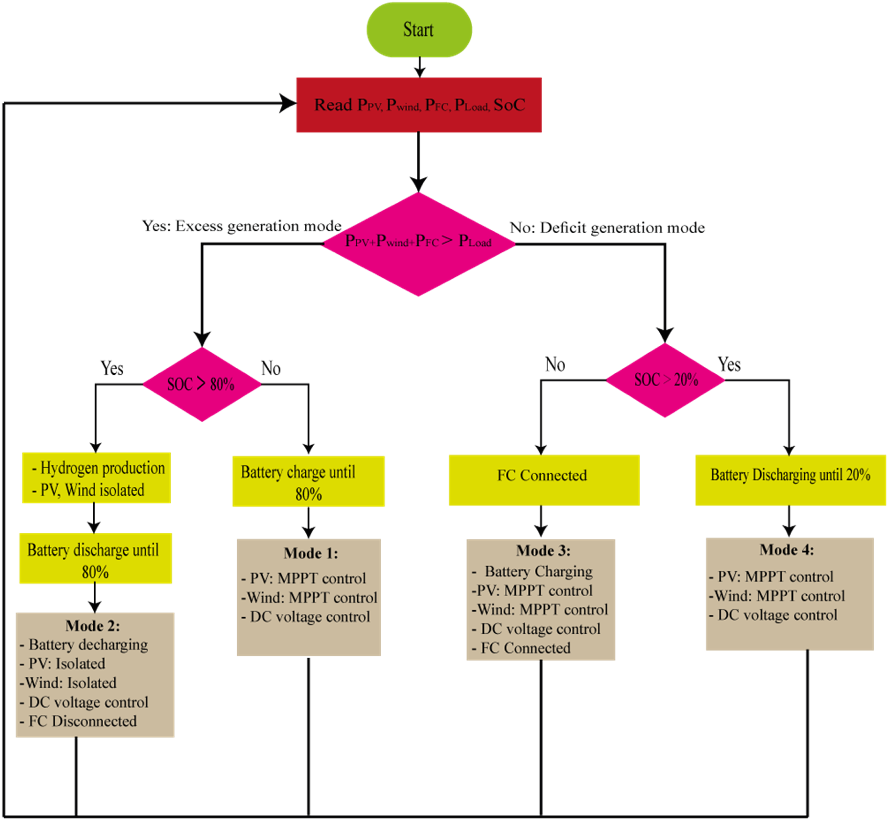
The primary aim of developing this system is to ensure a stable electricity supply to the load, despite varying system variables and environmental constraints. Renewable Energy Sources (RES) play a pivotal role in powering a microgrid. Given the inherent dependency of RES production on external factors and its tendency to exhibit substantial fluctuations, the ability to make informed decisions that adeptly adapt to these changing conditions is essential. The Perturb and Observe MPPT technique is employed to maximize power output from PV panels, wind turbines (WT), and FC. Furthermore, utilizing a controllable power generation device, such as a fuel cell, as an auxiliary power source alongside the battery, enhances the microgrid’s capability to supply electricity under diverse conditions.
The proposed EMS for a hybrid microgrid, designed to adaptively manage the power supply under varying conditions using a multi-modal operation strategy:
Mode 1 is the default operational state, where the system maintains the battery’s SoC within a predetermined optimal range, avoiding excessive charging or discharging. In this mode, the microgrid’s DERs perform under MPPT to efficiently harness renewable energy.
When the SoC rises above the maximum threshold, SoCmax (set at 80%), it indicates that the battery is approaching an overcharged state. To mitigate this, the battery begins to discharge, and excess power generation leads to the disconnection of PV and WT sources in the next time step, transitioning the system into Mode 2. The objective of Mode 2 is to bring the SoC back down to SoCmax by discharging the battery.
Mode 3 comes into play when the combined power from PV, WT, and FC is insufficient to meet the load demand and the SoC falls below the minimum limit, SoCmin (set at 20%). This shortfall triggers all available sources to operate at their maximum power output. If necessary, non-essential loads are shed to ensure critical loads continue to receive power.
Finally, Mode 4 activates to regulate the system when the SoC is within the acceptable range but requires close monitoring to maintain balance. All DERs continue operating at MPPT. Simultaneously, the fuel cell reverses into hydrogen production mode if the SoC is high, while the battery discharges as needed to support the load. This ensures that the microgrid can reliably supply power without interruption.
The EMS effectively prioritizes system stability and energy efficiency through these modes, dynamically adjusting to the fluctuations in energy production and consumption, thereby enhancing the reliability and performance of the hybrid microgrid.
Simulation results and discussion
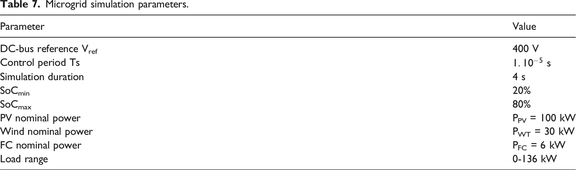
Microgrid simulation parameters.
Scenario 1 (SoC = 50%)
In the first scenario, the solar irradiation (Figure 10(a)) starts at 0 W/m2 at the beginning of the simulation and progressively builds up to a magnitude of 1000 W/m2. At the same time, the wind speed is fixed at 14 m/s, which results in nominal power production for the wind turbine generator and PV systems. It’s also important to note that the battery is set up with a SoC = 50%. Minimizing any negative effects on the DC and AC buses within the microgrid requires effective control and regulation of power generation from DERs. The variation of the FC temperature is shown in Figure 10(b). For periods less than a second, the PEMFC’s temperature is fixed at 30°C. In the time range of one to 2 seconds, there is a discernible increase in temperature of 30 degrees Celsius. Solar irradiation (a) and Fuel cell temperature (b).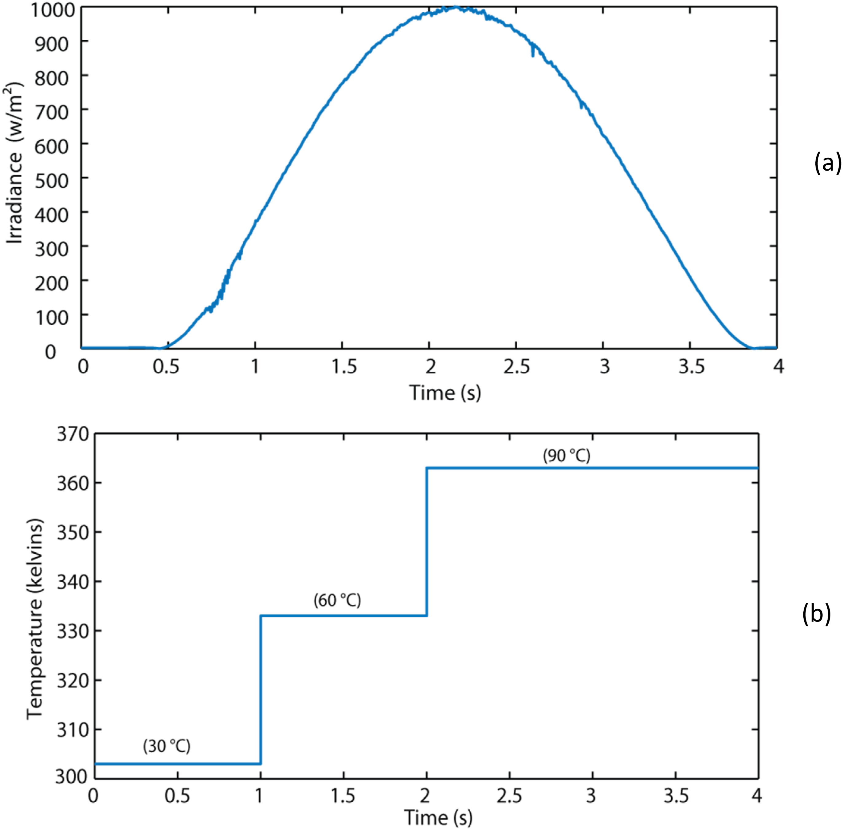
Both the DERs and load power play significant roles in testing the operation of the EMS, as depicted in Figure 11(a). The battery SoC, battery power, and DC bus voltage are shown in Figure 11(b)–(d), respectively. Notably, the battery undergoes discharge both at the start and conclusion of the simulation, particularly when the load power exceeds the generated power. During the period from t = 1.5 sec to t = 2.5 sec, the battery transitions to a charging state, contributing to bus stability and system equilibrium. The photovoltaic and wind turbine function in maximum power point tracking mode, while the fuel cell is integrated into the microgrid. The power generated by DERs and loads power (a) battery SoC (b) DC bus voltage (c) and battery power (d).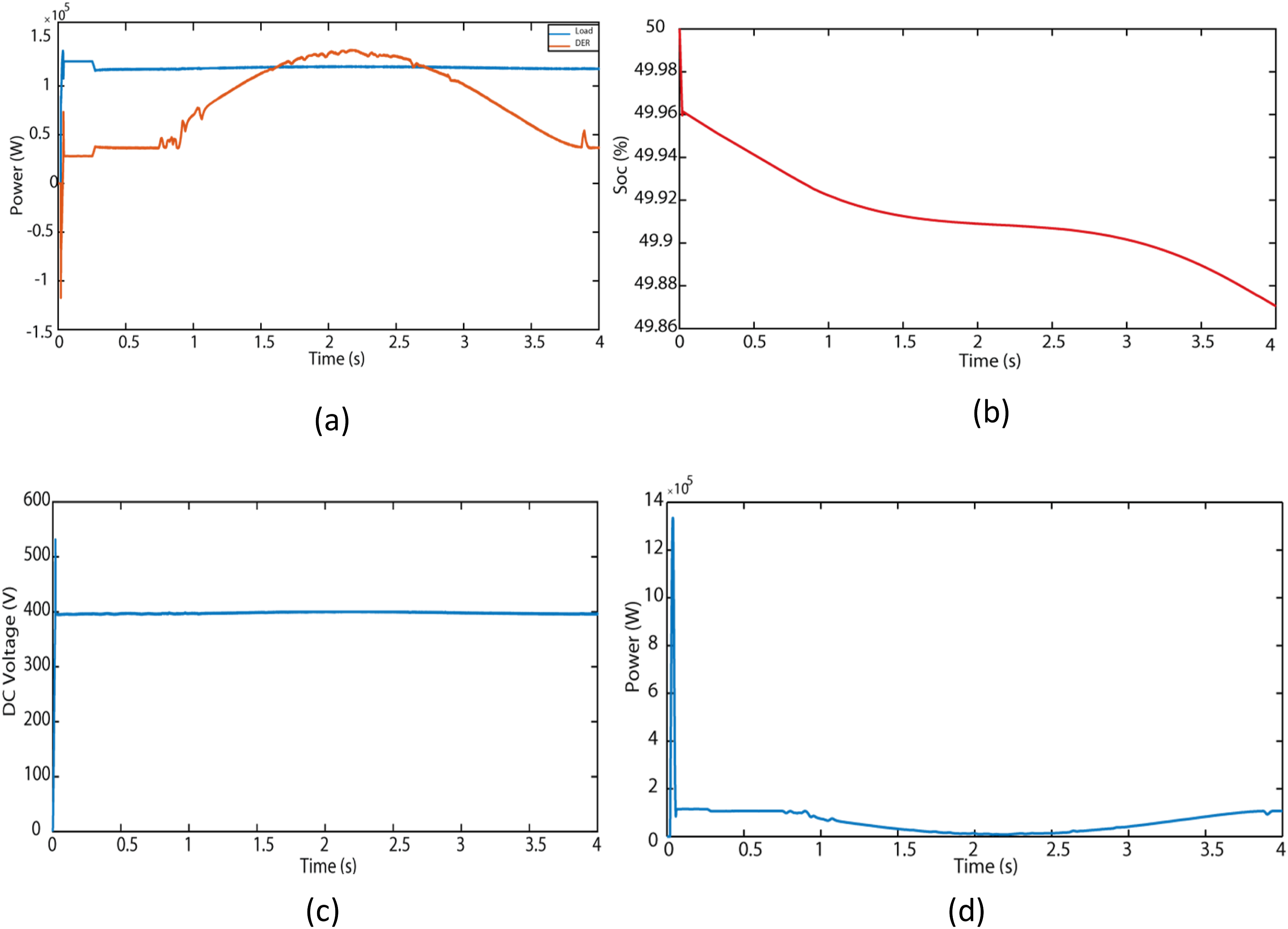
The well-regulated control mechanism ensures the stability of the DC bus voltage with minimal variations. In this scenario, the system operates under Mode-1 and Mode-4 of the proposed EMS, showcasing its adaptability to varying operational conditions.
Figure 12(a) illustrates the AC voltage behavior, which serves as compelling proof of the efficacy of the proposed EMS system in ensuring precise voltage management within the microgrid. This graph demonstrates the system’s capacity to effectively regulate and sustain the voltage of the AC bus, ensuring a consistent and reliable power supply to the electrical loads of the microgrid. In addition, Figure 12(b) illustrates the system’s frequency dynamics. The EMS scheme has successfully facilitated the MG meeting the specified AC electrical loads. Moreover, the proposed control approach exhibits exceptional proficiency in frequency stabilization and displays high adaptability to variations in the DC bus frequency within the hybrid microgrid system. AC bus voltage (a) frequency at the AC bus (b).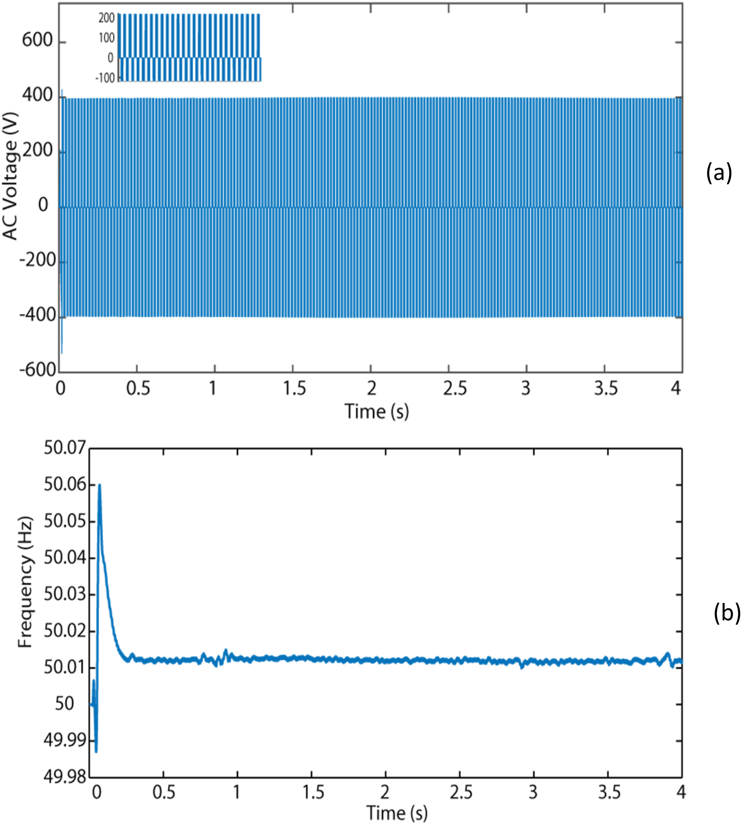
Scenario 2 (SoC = 20%)
In this particular scenario, the solar irradiance conditions from the first scenario are applied (Figure 10(a)). Figure 13(a) effectively illustrates the output power of the PV system within the proposed configuration. At the same time, the wind speed is shown in Figure 13(b). The energy recovered by the FC and the wind generator is represented by Figure 13(c) and (d), respectively. Figure 14 enables a comparison of the summation of DER power with the power from connected loads (comprising both AC and DC). This comparison reveals an imbalance in the power profile throughout the investigated time duration. Significantly, in this case, the battery SoC is close to its minimum threshold (20%), as depicted in Figure 15(a). The performance of the proposed EMS is considered under different load conditions, given these unique cases. PV power (a) wind speed (b) wind power (c) FC power (d). Power evolution of DERs and the load side. SoC of battery (a) DC bus voltage (b).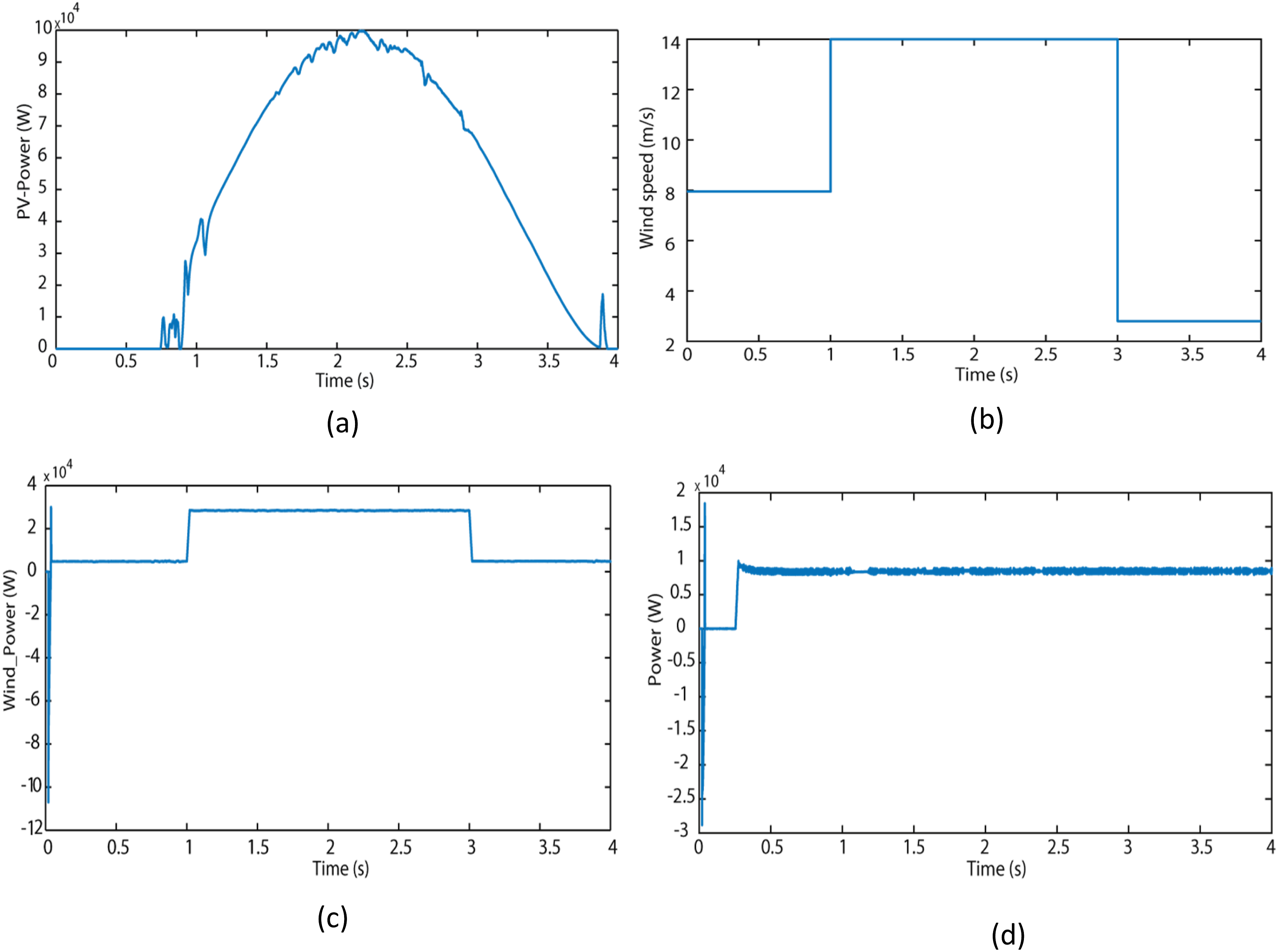
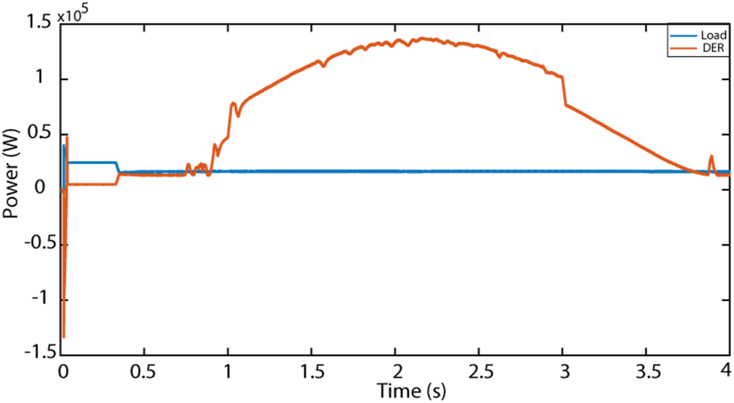
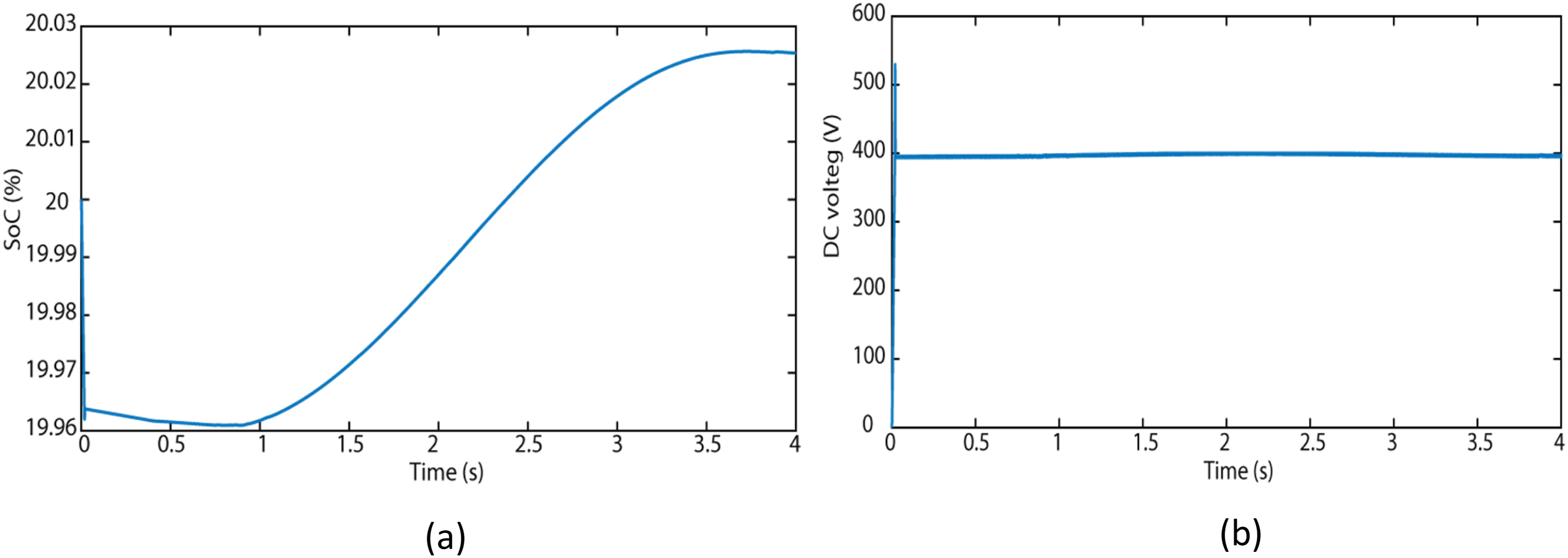
The initial load on the microgrid exhibited a condition where Pload exceeded the combined power output of PV, wind, and FC. At the same time, the SoC remained at 20%, as visually represented in Figure 15(a). In response, the proposed EMS takes action by operating the DERs in MPPT mode. The battery discharges to fulfill the load demand while ensuring the avoidance of deep discharges, thus safeguarding battery health. Between t = 1 sec and t = 3.8 sec, the load demands are lower than the produced power from DER, and the battery started to charge. As a result, the MG changes between Mode-3 and Mode-1 at (t = 1 sec). Therefore, an effective energy management system must be implemented to maintain a harmonious equilibrium between power generation and the desired loads. This is crucial for ensuring the stability and efficiency of the microgrid. The evolution of the DC bus voltage during the simulation is shown in Figure 15(b). It remains stable and precisely tracks the reference voltage during the simulation. (
Scenario 3 (SoC = 80%)
As shown in Figure 16, the battery SoC is getting close to its upper limit, SoCmax. The performance of the proposed EMS will now be evaluated under specific scenarios involving varying loads. Figure 17(a) illustrates the power and load consumption of the hybrid microgrid unit, with Pload set at 118 kW. Battery state of charge. MG unit’s power and loads consumption (a) DC bus voltage (b) AC bus voltage (c) and AC bus frequency (d).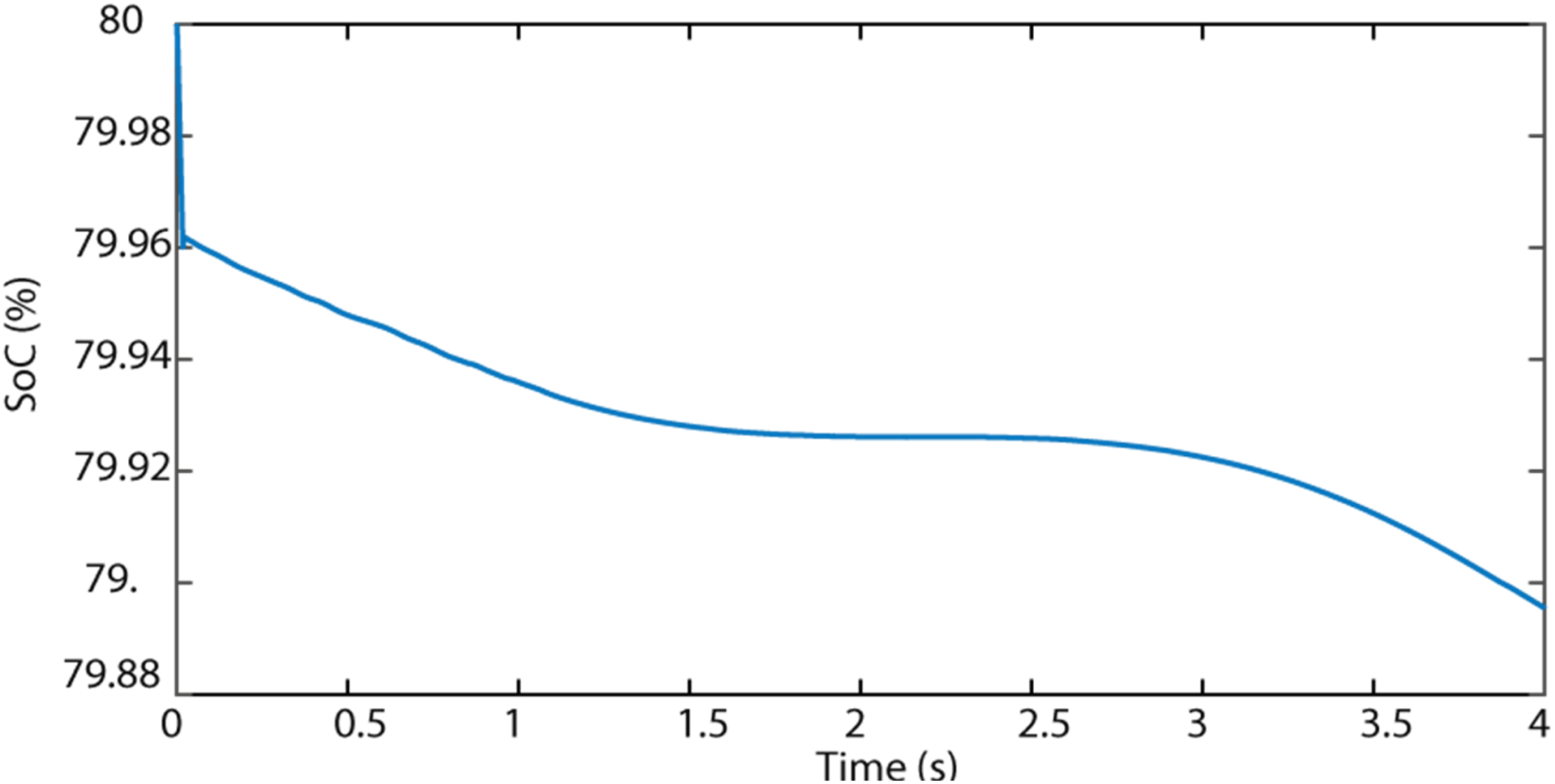
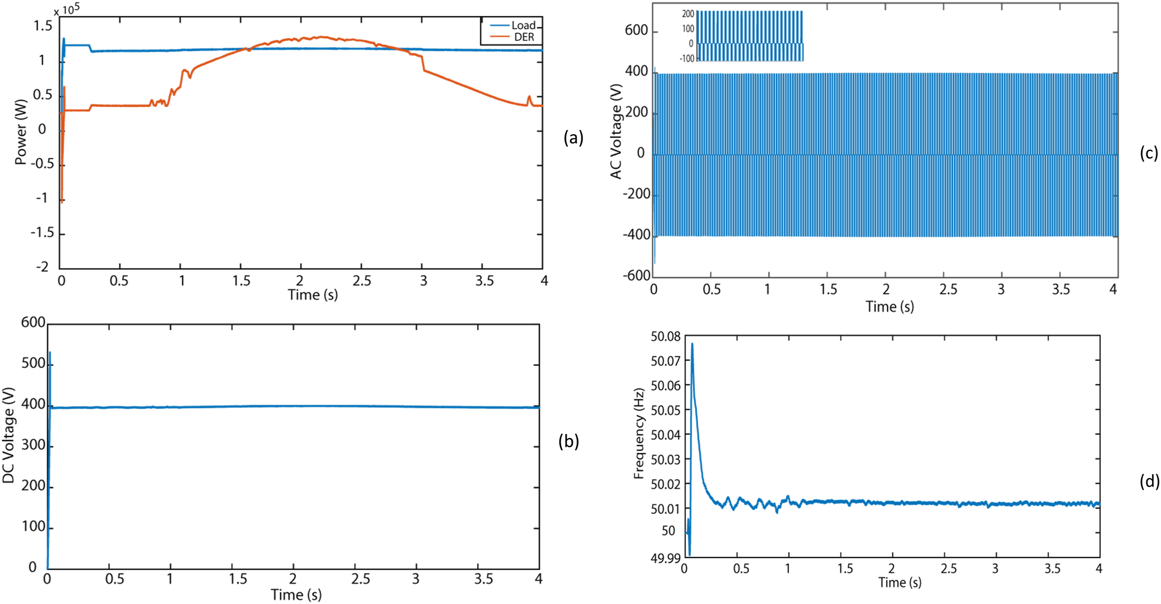
Figure 16 shows the SoC of the battery initially discharged during the simulation. At t = 1.5 sec, the battery also changes to a charging mode when there isn’t much power demand or when the amount of power created is higher than the amount needed. This filling process helps keep the bus stable and the system balanced. On the other hand, the battery device drains during high-power demand, especially around t = 2.75 sec, to keep the microgrid running smoothly.
The DC bus voltage is shown in Figure 17(b), which stays very close to the referenced DC bus voltage of 400 V. Furthermore, resistive loads are applied to the DC bus in each test scenario. The EMS controller is made to keep the voltage of the AC (Figure 17(c)) and DC buses at a predetermined reference value
To evaluate the effectiveness of the proposed control strategy, key performance indicators (KPIs) were used, including ΔVdc (max/RMS), Δf (max), THD, battery energy, hydrogen consumption, and fuel cell on-time. The results show that the DC bus voltage and frequency remain highly stable (ΔVdc ≤2 V, Δf ≤ 0.02 Hz), with THD below 2%. The battery energy utilization was optimized, maintaining a nominal capacity of 69 kWh while operating efficiently within the defined SoC range (20%–80%). The coordinated operation of the battery and fuel cell ensured smooth power balance, with minimal H2 consumption (≈0.0013 kg).These findings confirm the robustness and efficiency of the MAS-based EMS under dynamic operating conditions.
The simulation results confirmed the significant influence of the proposed energy-management strategy, which utilizes MAS, on the overall efficiency of the microgrid. An observed benefit is the enhanced stability of the DC bus voltage, which remains within a narrow band around the anticipated value. Furthermore, integrating a hydrogen-powered backup energy system is essential for improving the overall resilience of the entire system. By effectively managing hydrogen resources, the microgrid can ensure continuous power supply and prevent occurrences of blackouts.
Discussion and recommendations
The results demonstrate that the proposed multi-agent control strategy effectively manages energy flows in the hybrid microgrid under various operating scenarios. The proposed technique efficiently regulates the AC bus frequency, maintaining it close to the nominal reference value. Moreover, the proposal shows an advanced incorporation of various energy sources, energy storage technologies, and loads within the microgrid. The strategy’s main goal is to optimize power generation from renewable sources (PV and WT) while minimizing hydrogen usage. This approach improves the system’s efficiency and ensures optimal utilization of resources. Both islanded and grid-connected microgrids can enhance their overall reliability by using similar EMS technology. Multi-agent system controllers have demonstrated their reliability as an alternative to traditional proportional-integral controllers in various aspects of microgrid control. MAS controllers improve adaptability and coordination in managing distributed energy supplies, resulting in improved efficiency and reliability in microgrid operation.
Future research will concentrate on investigating ways to incorporate better hydrogen production and storage devices into the microgrid system. During periods of excess renewable energy, the feasibility of electrolysis to produce hydrogen will be evaluated, which can then be stored and used in fuel cells during energy shortages. Enhancing the sustainability and cost-effectiveness of microgrid operations will be the goal of analyzing the integration’s effects on the economy and environment. Further work will also explore advanced algorithms to optimize hydrogen production and predict energy demands, thereby increasing the resilience and autonomy of the microgrid system.
This paper advances microgrid control by combining a hybrid microgrid architecture, hydrogen energy storage, and a multi-agent system controller. Unlike previous studies using fuzzy logic (El Azzab et al., 2025; Hagras et al., 2008; Kalaiyarasan and Singaravelu, 2024) for energy management in limited settings, the MAS approach offers greater flexibility and better coordination across multiple energy sources and storage units. Compared with PID-based frequency control (Usman et al., 2025; Heidary et al., 2023), MAS provides faster response, improved load-sharing, and more robust performance under changing generation and demand. Unlike methods focused on AC microgrid power quality using signal-processing techniques (Raju and Srikanth, 2025; Satapathy et al., 2025), this study demonstrates practical performance under multiple scenarios, including load shedding, islanded operation, and integration of various energy sources. As a result, the proposed approach delivers higher reliability, efficiency, and optimal resource use, making it well-suited for complex DC microgrids.
For future implementations, it is recommended to explore the integration of advanced energy storage technologies, such as next-generation batteries and hybrid hydrogen systems, to further enhance microgrid reliability and autonomy. Incorporating predictive and adaptive control algorithms can improve the system’s response to rapid changes in renewable generation and load demand. Additionally, experimental validation using hardware-in-the-loop (HIL) or FPGA-based prototypes is advised to evaluate real-world performance and resilience against potential cyber-attacks. Finally, assessing the economic and environmental impacts of different energy-management strategies will help optimize sustainable and cost-effective operation for both islanded and grid-connected microgrids.
Conclusion
This paper introduces an innovative method for balancing and coordinating power generation and load supply in an isolated hybrid microgrid. The main objective of this technique is to develop an EMS specifically tailored to enhance the battery’s longevity by maintaining its SoC within an acceptable range. Furthermore, it aims to reduce the utilization of hydrogen fuel in a fuel cell. This technique is meticulously designed to guarantee the reliability of the system. Under normal circumstances, DERs operate in MPPT mode, an essential feature for optimizing the efficiency of renewable energy utilization. Furthermore, the EMS is responsible for supervising the battery bank and guaranteeing equitable power allocation among various sources and loads. In addition, it meticulously regulates essential factors such as AC and DC bus voltage while maintaining an appropriate frequency range. The simulations achieved in several scenarios offer convincing validation of the efficacy of the proposed EMS based on MAS in attaining a stable DC bus. Furthermore, the MAS control mechanism ensures inverters’ smooth and precise functioning. This study emphasizes the capacity of this strategy to improve the operational stability, efficiency, and reliability of hybrid microgrids, validating its practical utility in real-world scenarios.
Footnotes
Ethical considertions
Not applicable. This study did not involve any human participants or animal studies.
Author contributions
Mohamed Azeroual: Conceptualization, methodology development, simulations, data analysis, and manuscript drafting. Fatima Zahra Moughraoui: Simulation design and data analysis. Lahcen EL Iysaouy: Validation of results and manuscript drafting. Hassane EL Markhi: Supervision of the study, and manuscript review. All authors read and approved the final version of the manuscript.
Funding
The authors received no financial support for the research, authorship, and/or publication of this article.
Declaration of conflicting interests
The authors declared no potential conflicts of interest with respect to the research, authorship, and/or publication of this article.
Data Availability Statement
The data will be made available upon reasonable request.