



Abstract
An innovative design of jacking frames was developed for pin and hanger replacement in Robert Moses Causeway (RMC) bridge in Suffolk County, New York. The robust and efficient design of the jacking frames results in a system with improved safety, performance, constructability, and economy. A fully integrated approach for design, fabrication, and construction was employed for higher quality and efficiency. A detailed and precise 3D model was created and directly used for finite element (FE) modeling, producing contract and shop drawings, and designing of temporary work platforms. This paper provides an overview of the integrated design approach and system design, and documents the computational study for this system (global analysis, stress analysis, and large-displacement stability analysis). There are many aging steel bridges in the U.S. and abroad that have similar pin and hanger systems, and jacking frames will be needed to replace those pins and hangers when they exhaust their useful service life. The concepts and details of the jacking frames can easily be emulated by engineers for developing similar safe and robust systems for suspended truss spans and other applicable bridge structures.
The Robert Moses Causeway (RMC) is an 8.10-mi long parkway in Suffolk County, New York. The Fire Island Inlet span (Figure 1) was constructed in 1964, and its main spans are made of steel trusses, consisting of two 233.3 ft. anchor spans, two 66.7 ft. cantilever spans, and one 466.7 ft. suspended span. The suspended span is supported by two sets of pins and hangers at each end (Figure 2), and each hanger has about 600-ton of tension under service dead and live loads.

Robert Moses Causeway (RMC) bridge.

Pin and hanger system.
Before replacement, the original pins and hangers had been in service for about 54 years, and showed signs of deterioration, such as rusting and potentially frozen pins. Therefore, the bridge owner, New York State Department of Transportation, decided to replace them in kind. The construction project was awarded to Skanska USA Civil, and CHI Consulting Engineers was retained by Skanska to design jacking frames and supports.
Method
To replace the existing pins and hangers, they first need to be unloaded by jacking while maintaining the vertical loads from suspended span and accommodating its movements. It is a great challenge to perform this operation safely and efficiently. Since the spans are over water, the most efficient jacking approach was to push up the suspended span against the cantilever spans. Given the space constraint, common jacking methods, such as attaching steel brackets on the face of the gusset plates, would most likely cause twist and stresses in the gusset plates because of the eccentricity of jacking loads and might not accommodate longitudinal and rotational movements of the superstructure well.
System Design
A unique design of jacking frames/temporary supports was developed, and it is original and innovative in the following two aspects: 1) efficient and robust system design, and 2) integrated approach for design, fabrication, and construction.
Figures 3 and 4 illustrate the design of the system which consists of the following:
A lower jacking frame which sits on top of the existing gusset plates in cantilever spans
Two 400-ton hydraulic jacks, which are synchronized by a hydraulic system, and Polytetrafluoroethylene (PTFE) sliding bearings underneath
An upper jacking frame which connects to the existing truss vertical member in the suspended span
Two longitudinal bracing members which resist frictional forces from PTFE sliding bearings

Setup details: upper and lower frames, Polytetrafluoroethylene (PTFE) sliding bearings, and jacks.
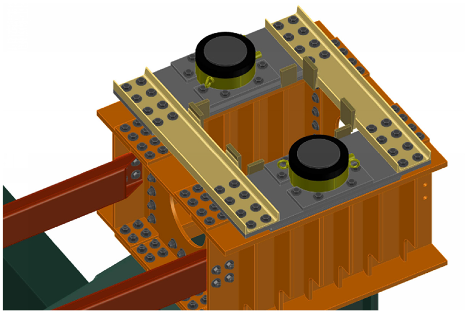
Lower frame, PTFE (Polytetrafluoroethylene) sliding bearings, and jacks.
The upper jacking frame was bolted to the truss vertical member. Instead of drilling new holes, most bolts were installed at the locations of existing rivets to minimize the amount of section loss. The rivets were removed and replaced with A490 high-strength (HS) steels bolts, one face at a time. The lower jacking frame sits directly on gusset plates via grooves (Figure 5); therefore no rivet removal and bolting was required, allowing faster installation and removal. The bending moments from the eccentricity of the jacks to the gusset plates were resolved within the lower jacking frame so that the existing gusset plates only resist vertical loads in their planes. The grooves in the lower jacking frame also maintain the original geometry/shape of the gusset plates so that they would not twist, and consequently make pin removal and installation easier. Beneath the hydraulic jacks, PTFE sliding bearings accommodate expansion and rotation of the suspended span under wind, live, and temperature loads.

Details of lower frame and groove.
Integrated Approach
To improve quality of design and minimize fit-up issues during construction, a very detailed and precise 3D AutoCAD model of the jacking frames and adjacent truss members was created, as shown in Figures 3–5. This model includes all steel plates, rivets, and new bolts. The geometry of the 3D model was directly transferred to Midas FEA program for finite element modeling and analysis. Detailed stress and nonlinear large-displacement stability analysis were performed to check the adequacy and safety of both existing and temporary structures. The model was also used for producing high-quality 2D design drawings and 3D images for illustrating step-by-step erection process.
The 3D model was also used for fabrication and construction. It was shared with the fabricator for producing shop drawings, resulting in less errors and faster turnaround time. Any proposed changes from the shop drawings were synchronized in the 3D model to keep all models current. The contractor, Skanksa, also expanded the model to include temporary work platforms and access. This fully integrated approach (Figure 6) for design, fabrication, and construction resulted in a workflow with higher efficiency and quality.

Schematic diagram integrated approach.
Global Analysis
During the construction stage, the load path within the structural members adjacent to the pin and hanger being replaced was altered. Additionally, the pin and hanger sets were replaced with a jack framing system leading to the change of support boundary conditions. Global model analysis was therefore performed to examine the adequacy of member strength and longitudinal displacements of the suspended arch span.
Global model analysis was performed in Midas Civil 2017 (v2.2). As shown in Figure 7a, the model only included beam and truss elements for truss members, laterals, floor beams, hangers, ties, sway frame struts, and sway frame diagonal bracings. The elements of deck, stringers, diaphragm, fascia, railing, and posts are not explicitly modeled, but their dead loads are distributed on the floor beams based on their tributary areas. Live loads are applied as linear loads on top of floor beams.

Global analysis model: (a) Midas finite element model and (b) swing pendulum system.
The global analysis consists of two models: the existing condition for the preconstruction stage and the temporary condition for the construction stage. In the existing condition, four sets of pins and hangers vertically support the suspended arch span and function as a swinging pendulum as illustrated in Figure 7b. They accommodate longitudinal displacement as well as provide a longitudinal restoring force. For this analysis, the contribution of pin friction to the restoring force is ignored and the equivalent stiffness is approximated by Equation 1 allowing a conservative estimate of longitudinal displacements. Therefore, they were modeled as elastic springs with a calculated longitudinal stiffness value of 14.6 kips/in. In the temporary condition, the longitudinal restraint is released at the location where the pin and hanger are being replaced.

The design loads and load combinations conform with AASHTO Standard Specifications for Highway Bridges, 2002 ( 1 ). Dead loads, live loads, longitudinal force, impact loads, thermal loads, wind loads on structure, and wind loads on live loads were considered in the model. The construction of pin and hanger replacement was scheduled to be completed within 4 months, therefore a reduction factor of 0.73 for wind speed is permitted by AASHTO Guide Specifications for Wind Loads on Bridges During Construction, 2017 ( 2 ).
Reaction forces and axial forces in the truss members adjacent to the pin and hanger were compared between the existing model and those from as-built drawings. The global model is reasonably accurate, with the maximum differences below 6% for the dead load, and 10% for the dead load, live load, and impact load combined.
The comparison between the existing and temporary condition shows that the force changes in all the truss members adjacent to construction location were negligible except for vertical member supported by the pin. Loads in the vertical member changed significantly, since the load path in the vertical member was altered by the installation of the temporary frame.
For the suspended span in the temporary condition, the D/C ratios of all truss members near temporary supports are less than 1.0 under any load combinations during construction. Longitudinal displacements are less than the maximum clearance of existing finger joints, 4 in.
Stress Analysis
A finite-element (FE) structural analysis was conducted to evaluate the design of the temporary jacking frames. Given the jacking loads obtained from the global analysis, the stresses of the jacking frames and neighboring existing structural members were evaluated in the detailed local FE models created in MIDAS FEA for the lower and upper temporary jacking frames separately.
Lower Jacking Frame
Figure 8 depicts the FE model of the lower temporary jacking frame, together with the adjacent existing gusset plates, bottom chord, diagonal member, and a portion of the floor beam in the cantilever span. All the structural details, such as steel angles, perforations, and fill plates were included and accurately modeled. The model is laterally restrained at the floor beam connected to the inner gusset plate, and fixed at the far ends of the diagonal and bottom chord such that it is able to reproduce the consistent member forces with those obtained from the global model when subjected to jacking loads given the statically determinate nature of the structure. Loads (either vertical or transverse) are applied as distributed pressure on the two plates on top of the lower temporary jacking frame with a combined vertical load of 1181 kips, comprised by three loads: DL = 965 kips, LL = 199 kips, and IM = 17 kips.

Finite-element (FE) model for lower frame and supporting structure in anchor span.
Figure 9 shows the mesh of the FE model. Linear elastic material and quadratic tetrahedral solid elements were used for all the steel components. This element is capable of modelling curved geometry and capturing the out-of-plane deformation of the thin-walled structure with high accuracy. Multiple layers of elements are used for a structural member where the out-of-plane deformation is the focus of the analysis. For instance, gusset plates, which consist of three layers of steel plates on each side, are modeled with three layers of elements.

Mesh of finite-element (FE) model.
Figure 10 presents the Von Mises stress contour in the proximity of the lower jacking frame and its close-up view. The stresses within the jacking frame are mostly under 20 kips per square inch (ksi) (which is acceptable for Grade 50 steel) except for a few “hot spots” where stresses around 30.0 ksi are observed. Further sensitivity study confirms that they are local numerical singularities occurring at geometric discontinuities and should be ignored.

Von Mises stress of the lower frame (kips per square inch [ksi]): (a) in proximity of the lower frame and (b) close-up view.
As shown in Figure 11, the stresses in the existing gusset plates are smaller, mostly under 15 ksi, which is much smaller than the 27.0 ksi allowable stresses of HS steel. Similar to the temporary jacking frame, a few “hot spot” stresses of 30.0 ksi were observed, which are likewise to be ignored.

Von Mises stress contour of the existing gusset plates (kips per square inch [ksi]).
The average Von Mises stress is less than 18.0 ksi in the diagonal member, and between 10.0 and 14.4 ksi in the bottom chord, which are less than the 27.0 ksi allowable stress for HS steel (Grade 50). There are some stress concentrations around the perforations in the cover plates, and the maximum stress is less than 32.4 ksi. This is considered as normal and acceptable. Based on the above observation, the stresses in the lower temporary jacking frame and the supporting existing gusset plates are satisfactory during the jacking operation.
Upper Jacking Frame
The addition of the jacking frame altered the load path in the existing structure of the suspended span. Figure 12 illustrates the change of member forces in the existing structure before and during the hanger replacement, obtained from the global analysis results. Before the replacement, the vertical member is experiencing a compression of 301 kips in response to the combined vertical reaction of 1,181 kips at the lower pin location. During the pin replacement, however, the suspended span will be supported at a higher elevation in the vertical member U9-L9 through the jacking frame, causing a tension of 877 kips in the vertical beneath the jacking frame.

Schematic force diagram for load path in suspended span members: (a) before replacement and (b) during replacement.
The upper temporary jacking frame was modeled along with the adjacent existing structural members in the suspended span including the gusset plates, bottom chord, vertical and diagonal member, and a portion of the floor beam, as depicted in Figure 13. The model is fixed at the far ends of the diagonal and bottom chord, and laterally restrained at the floor beam and the top of the vertical. Apart from the 1181 kips jacking force acting on the upper frame, a vertical force of 304 kips calculated from the global analysis was applied at the top of the vertical to reproduce consistent diagonal M10-L9 and bottom tie L10-L9 forces, with those from the global model exploiting the static determinacy of the modeled local structure. The purpose of this model was to determine the stress in the frame and examine the effect of load path change on the existing structure, particularly the gusset plate and the vertical member. The diagonal and bottom chord were not the focus of this analysis, since the global analysis shows their member forces were not notably affected by the load path change.

Finite-element (FE) model for the upper frame and attached structure in the suspended span.
Figure 14 presents the Von Mises stress contour in proximity of the upper temporary frame and its close-up view. The stresses within the frame are mostly very low except near the jacking stiffeners (under 25 ksi, which is acceptable for Grade 50 steel).

Von Mises stress contour in proximity of the upper frame (kips per square inch [ksi]): (a) in the proximity of the upper frame and (b) close-up view.
The axial stress in the vertical member U9-L9 is examined in Figure 15, since a tension (877 kips) with a magnitude almost three times the pre-existing compression (301 kips) will be introduced during the hanger replacement because of the change of load path. The maximum tensile stresses are located between the jacking frame and the gusset plates, with the average magnitude under 12 ksi, which does not exceed the 18 ksi allowable stress limit for carbon steel (Grade 36) in axial tension. Von Mises stress in the vertical member is considerably lower than its yielding stress. Except for the presence of stress concentration in local areas (e.g., near the perforations), no value greater than 25 ksi can be found.

Axial stress contour for the vertical member U9-L9 (kips per square inch [ksi]).
Nonlinear Stability Analysis
Two large-deformation analysis load cases were performed to determine the safety factor against global instability or local buckling. The steel was considered as a linear elastic material in the analysis while the geometric nonlinearity was considered. Lateral forces that account for the maximum frictional forces (5% of the vertical loads) were applied on top of the lower jacking frame. This is a very conservative assumption, as the actual friction coefficient is not expected to exceed 3% at the most severe temperature conditions. To evaluate the safe factor of local buckling, additional load cases with 2.5 times of the original vertical and lateral forces were also considered.
The deformed shape for D2 is depicted in Figure 16 as an example. No discernible local twist deformation pattern was observed. In this case, the Von Mises stresses are still mostly below 50 ksi even under 250% load level. Though such stress level is unlikely to be reached, it nevertheless validates the linear elastic material assumption used for this analysis.

Lateral displacement contour on deformed shape for case D2 (unit: inches).
Table 1 presents the load cases and the maximum lateral displacements for each. At 250% load level, the lateral displacements at the top of gusset plate and lower frame are 0.511 in. and 0.726 in. Based on those at 100% load level, their calculated amplification factors are 1.048 and 1.052 at 250%, respectively. In contrast, the amplification factor rises to infinite with load level approaching critical load. These lateral amplification factors are insignificant compared with the generally acceptable value 2.0 ( 3 ). It can therefore be concluded that the structure system has a safety factor greater than 2.5 against local buckling or global instability.
Maximum Lateral Displacements

Summary
This robust and efficient jacking frame design for the pin and hanger replacement achieves improved safety and performance compared with conventional jacking schemes. It better accommodates the longitudinal and rotational movements of the superstructure during the jacking, without introducing eccentric load on the load-bearing gusset plates. It was easier to install and remove, allows faster construction, lower costs, and has less effects on public traffic.
A fully integrated approach for design, fabrication, and construction was employed. A detailed and precise 3D model was created and directly used for FE modeling, producing contract and shop drawings, and designing of temporary work platforms, achieving a workflow with improved quality and efficiency.
Figure 17 presents the erected temporary jacking frames. All pins and hangers were replaced in October 2018, within budget and on schedule. There are many aging steel bridges in the U.S. and abroad that have similar pin and hanger systems, and jacking frames will be needed to replace those pins and hangers when they exhaust their useful service life. While each individual pin and hanger system might differ in design details, the concepts and details of this jacking frame system can easily be emulated by engineers for developing similar safe and robust systems for suspended truss spans and other applicable bridge systems.

Erected temporary jacking frames/supports: (a) jacking frames, (b) removal of the pin, and (c) new hanger in place.
Footnotes
Acknowledgements
This is to acknowledge the support from the bridge owner, New York Department of Transportation (Region 10), and the general contractor, Skanska USA Civil.
Author Contributions
The authors confirm contribution to the paper as follows: study conception and design: Q. Ye, L. Han, D. Wei; data collection: L. Han, D. Wei; analysis and interpretation of results: L. Han, D. Wei; draft manuscript preparation: L. Han, D. Wei, Q. Ye. All authors reviewed the results and approved the final version of the manuscript.
Declaration of Conflicting Interests
The author(s) declared no potential conflicts of interest with respect to the research, authorship, and/or publication of this article.
Funding
The author(s) disclosed receipt of the following financial support for the research, authorship, and/or publication of this article: This project was supported by the Skanska USA Civil.
Data Accessibility Statements
Data supporting the findings of this study are included in the published paper