
Abstract
Beginning in 2018, the precast concrete pipe producers of the Minnesota Concrete Pipe Association (CPA) worked with the Minnesota Department of Transportation (DOT) to update the standards for reinforced concrete arch pipe. The Minnesota DOT standard plates include steel reinforcement areas for both circumferential steel and transverse steel (stirrups) where required. The latest Minnesota DOT standards include pipe classes in accordance with AASHTO M206 (or ASTM C506) as well as some larger sizes and higher strength classes that are not included in the AASHTO standard. The reinforcement designs for these larger sizes were performed in accordance with the 8th Edition of the AASHTO LRFD Bridge Design Specifications and were formulated to encompass the worst of either the loads from the field installation, or the testing loads in three-edge bearing. The three-edge bearing test requirements tended to govern the required steel area for transverse reinforcement. However, the field conditions governed the extent to which the transverse reinforcement needs to extend out from the invert of the pipe.
In 1996 the American Association of State Highway and Transportation Officials (AASHTO) adopted the Standard Installations for concrete pipe into the AASHTO Standard Specifications for Highway Bridges ( 1 ). The Standard Installations consist of a generic trench detail with four specified levels of compaction, bedding thickness, and soil types. Since then, the Standard Installations have provided the basis for concrete pipe design and continue to be used in the AASHTO LRFD Bridge Design Specifications ( 2 ).
The design method for the Standard Installations was developed through physical testing and Finite Element Method (FEM) modeling of circular concrete pipe. Because circular pipe accounts for the overwhelming majority of installations around the country, there was never any research performed on elliptical or arch pipe shapes. However, when AASHTO adopted the Standard Installations into its specifications, they deemed it necessary to incorporate the same installation practices for all shapes of concrete pipe. Thus, the elliptical and arch pipe shapes incorporated soil materials and compaction levels consistent with those of the four Standard Installations for circular concrete pipe (see Figures 1 and 2).

Standard installation for circular concrete pipe.
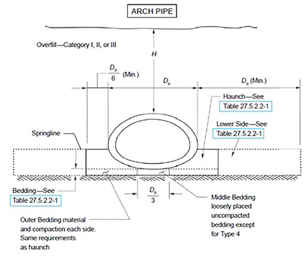
Standard installation for arch concrete pipe.
The Minnesota Department of Transportation (DOT) publishes their own supplemental standards for reinforced concrete pipe of both circular and arch shapes. In 2018, Minnesota DOT elected to update their reinforcement designs and fill height tables to correspond to the Standard Installations in accordance with AASHTO. In addition to this, they sought to update the designs of some larger sizes of concrete pipe that are commonly used throughout the state but do not have standard designs listed in the AASHTO specification.
The additional sizes not covered by the standard tables in AASHTO generally require special designs which use transverse reinforcing steel (stirrups) to address shear and radial tension. Thus, the concrete pipe industry, in cooperation with Minnesota DOT, formulated a standard method for designing arch pipe installed according to the Standard Installations in AASHTO.
Three-Edge Bearing Design
Compared with circular pipe, which has a constant radius, arch pipe design is significantly more complicated given its shape having three varying radii (one for the top, one for the corners, and one for the bottom). As specified in AASHTO M206 (ASTM C506), arch pipe designs can be broken down into three basic classes of pipe: Classes A-II, A-III, and A-IV ( 3 , 4 ). Depending on the class, the pipe must withstand a particular loading in a three-edge bearing test. In this test, a design load produces moments in the pipe wall that are proportional to the expected moments in field conditions by a given value called a “bedding factor” determined by the type of installation. To begin the development of a relationship between field and testing moments for arch pipe, the initial design model determined maximum moments experienced by an arch pipe subjected to a three-edge bearing loading apparatus. Subsequent analysis on the pipe for the installed condition were performed after this.
For circular pipe, the moment equation in the three-edge bearing test is calculated as ( 1 ):

where
M3EB = moment at the invert or crown in three-edge-bearing from the applied load (in-lbs/ft),
P = line load along the top of the pipe (lbs/ft), and
r = mean radius of the pipe (in.).
Similar equations to this also exist for determining shear and thrust values. The 0.318 coefficient is a useful tool for design purposes as it provides a single constant value that can be multiplied by any pipe radius and any applied load to determine the resulting maximum moment. However, the moment equation for an arch pipe is not as easily obtainable. Compared with circular pipe, which has a constant radius, arch pipe requires a much more intricate analysis because of its shape consisting of three radii (see Figure 3). A simplified, closed-form solution could not be readily developed for arch pipe, so it was necessary to depend on computer modeling software to determine the magnitude of the design coefficients.

Reinforced concrete arch pipe drawing.
Several FEM runs were performed using the CANDE 2-D FEM software for the three-edge bearing test (see Figure 4) to establish basic moment, shear, and thrust coefficients. Separate coefficients were established for the invert, springline, and crown of the reinforced arch pipe and incorporated into a spreadsheet so that subsequent calculations could be performed using a simplified and more universal design system. The CANDE runs used a concrete strength of 5,000 pounds per square inch (psi), which is consistent with the higher classes of arch pipe. A steel yield strength of 75,000 psi was used for the reinforcement. ASTM C506 has a required minimum yield strength of 65,000 psi for arch pipe reinforcement. However, CANDE uses an elastic-plastic curve for the reinforcement steel, which is not a very accurate model for the wire reinforcing which tends to have a power curve for its stress–strain relationship. Past models have shown that using the 75,000 psi value helps to compensate for this behavior.
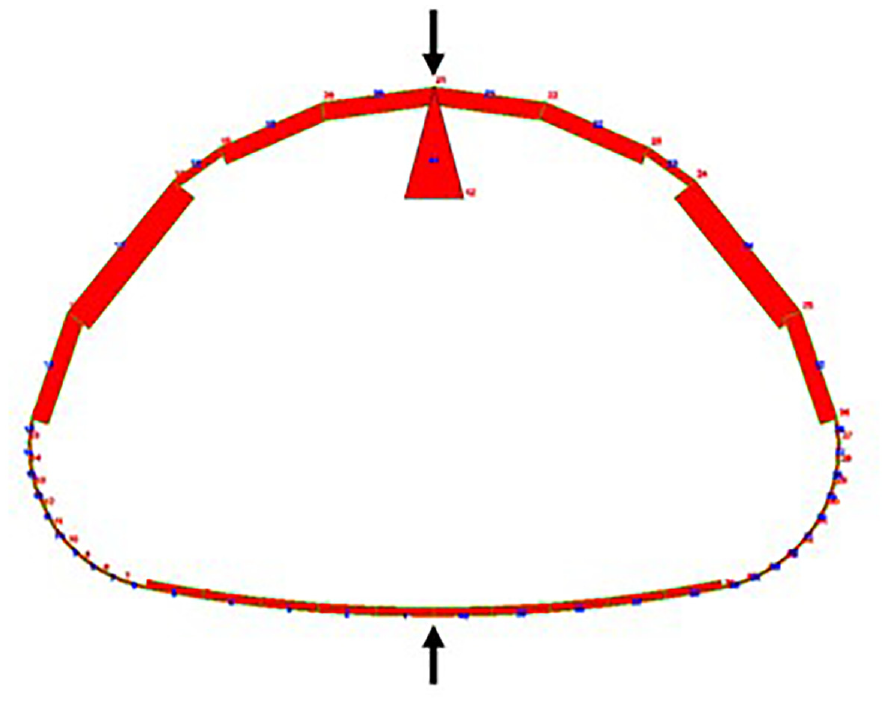
CANDE 3.E.B. model.
The CANDE runs were performed for arch equivalent round sizes of 60, 72, 84, 90, and 120 in. The analysis for the 60-in. equivalent was performed first using the steel areas from the existing Minnesota DOT tables. Following this run, the resulting design coefficients were extracted from the FEM run of the 60-in. pipe and incorporated into a spreadsheet that designed the steel reinforcing for the 72-in. pipe. The resulting design was then analyzed in a CANDE FEM run for the 72-in. pipe. This iterative process was repeated for each subsequent size to establish and verify a consistent design basis for use in a design spreadsheet.
Although ASTM C506 tables specify the same inner reinforcing values for the top and bottom of the arch pipe, the initial CANDE run used a slightly lower inner steel area at the top versus the bottom of the pipe. This was based on the values in the earlier Minnesota DOT reinforcement tables for arch pipe. Shortly after beginning this process, Minnesota concrete pipe producers determined it would be more accurate to use the same steel area for the top and bottom of the pipe based on common manufacturing practices. So the assumed flexural steel area at the top of the pipe was then changed to match the bottom. After the change, this resulted in the top of the pipe experiencing a slightly higher moment, but only by roughly 2%.
Subsequent CANDE runs were compared with each other to ensure the consistency of the design method and its results in the FEM program. Moment coefficients were obtained from the CANDE program for both the 0.01-in. design load and the ultimate load to incorporate any moment redistribution after cracking. The moment coefficients were relatively consistent for both loading situations with the ultimate moment coefficient for the invert of the pipe being very slightly higher at the ultimate load than at the 0.01-in. crack load. Because CANDE is limited by a linear modulus for the steel reinforcement, it cannot perform an entirely accurate design for the reinforced concrete pipe when considering ultimate flexural strength. However, the results were considered accurate enough for the development of the design coefficients.
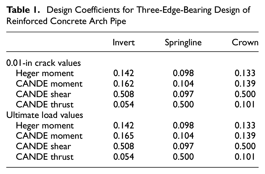
The final design coefficients established for the three-edge bearing design of reinforced concrete arch pipe through the use of CANDE are shown in Table 1. Additionally, previous theoretical research completed by F.J. Heger had suggested moment coefficients for arch pipe ( 5 ). These values are included in Table 1 for comparison purposes.
Design Coefficients for Three-Edge-Bearing Design of Reinforced Concrete Arch Pipe
Design Depths for Arch Pipe
Based on their most current bedding and installation requirements, Minnesota DOT assumes a Type 3 Installation for determining their design bedding factor. With this base assumption, the American Concrete Pipe Association’s (ACPA) LRFD fill height tables for arch pipe were used to establish the maximum allowable fill height for Minnesota DOT’s Reinforced Concrete Arch pipes ( 6 ). The reinforcing tables in AASHTO M206 for arch pipe have three classes of pipe each related to a particular D-Load which is a load per foot of span per foot of length. This is similar to the pipe classes in AASHTO M170, although M206 pipe is only specified as Class A-II, A-III, or A-IV (1,000, 1,350, and 2,000 lbs/ft/ft, respectively) whereas M170 also covers Class I and Class V pipes (800 and 3,000 lbs/ft/ft, respectively). Seldom is an arch pipe required with a higher strength than a Class IV. Thus, the development of the new fill height tables for Minnesota DOT stopped at a Class IV but extended to much larger sizes that are not specified in M206.
When correlating the field conditions to a class of pipe, a bedding factor is used to compare the critical moment experienced by the pipe in the field to the critical moment experienced by the pipe in the three-edge bearing test. Thus, after developing a design method for the three-edge bearing situation it was important to take an extensive look at the relationship between the three-edge bearing test results versus the correlating field design as well as the differences in the current AASHTO design method for arch pipe versus what had been used in the past. With the exception of a couple of sizes, 17 ft is the maximum fill height allowed for a Type 3 Installation of Class IV arch pipe per the ACPA LRFD Fill Height Tables. The previous Minnesota DOT tables allowed Class IV arch pipe (all sizes) down to 23 ft. The Minnesota DOT designs were based on older methodologies before the development of the LRFD method currently used by AASHTO.
The first phase of this evaluation was the comparison of a true Marston/Spangler design to the design procedure now included in AASHTO based on simplified methods used to try to make the arch and elliptical pipe installations consistent with the circular pipe installations.
With the adoption of the Standard Installations into AASHTO for arch pipe, the previous equations in AASHTO had to be modified to be more consistent with the equations for circular pipe. Previously, the equation for load on an elliptical pipe was expressed as:

where
WE = weight of earth on the pipe (lbs/ft),
Cc = load coefficient,
w = unit weight of soil (pcf), and
Bc = outside span of the pipe (ft).
The new equation for the Standard Installations is expressed as:

where
FE = soil–structure interaction factor, and
H = height of earth cover over the top of the pipe (ft).
The multiplication of wBcH results in a value for the overburden load above the pipe, called the soil prism. The soil–structure interaction factor—also referred to as the vertical arching factor—accounts for how much the soil prism load above the pipe is increased as a result of soil settlement adjacent to it. While the Standard Installations have a fixed vertical arching factor for each type of installation, the Marston/Spangler designs have a variable factor depending on the assumptions made for: the amount the pipe projects above the natural ground surface when installed (the projection ratio, p); the relative settlement of the soil prism above the pipe to the adjacent prisms (the settlement ratio, rsd); and the fill height above the top of the pipe. The soil–structure interaction factor for a Type 3 Installation is 1.40. If the value of the soil prism were divided out of the previous load equation, then the resulting soil–structure interaction factors for the old Class B and C beddings would be in the range of 1.25 to 1.41 for pipe installed to fill heights within the range of 10 to 20 ft. This is a wide range of soil–structure interaction factors. However, the recommendation of a projection ratio of roughly 0.7 by the ACPA, along with design tables and graphs supplied by them over the years based on rsdp of 0.5 (the rounding of a settlement ratio of 0.7 multiplied by a projection ratio of 0.7), results in vertical arching factors between 1.25 and 1.35 ( 7 ). Thus, the simplification of arch design for incorporation of the Standard Installation parameters tends to increase the design loads on the pipe.
In addition to the load on the pipe, the support provided to the pipe by the lateral soil pressure and vertical bedding reaction must also be considered. The current equation for determining the bedding factor for arch and horizontal elliptical pipe is:

where
Bfe = earth load bedding factor,
CA = a constant corresponding to the shape of the pipe,
CN = a parameter which is a function of the distribution of the vertical load and vertical reaction,
x = a parameter which is a function of the area of the vertical projection of the pipe over which lateral pressure is effective, and
q = the ratio of the total lateral earth pressure to the total vertical fill load.
This basic equation is no different now than what it was in the AASHTO Standard Specifications years ago. However, the definition of the variable “q” had to be modified with the incorporation of the vertical arching factors from the Standard Installations. The equation for “q” before 1996 was:

where
Cc = load coefficient for embankment installations, and
p = projection ratio of the vertical distance between the outside top of the pipe and the ground or bedding surface to the outside vertical height of the pipe.
With the incorporation of the Standard Installations, the load coefficient Cc was dropped for the use of the soil–structure interaction factor (vertical arching factor) Fe in its place. However, these two terms are not identical. If we set Equations 2 and 3 equal to each other, we can determine the load coefficient in relation to the soil–structure interaction factor.

When this gets plugged into Equation 5, the ratio of lateral earth pressure then becomes:

In reviewing Equation 7, it can be seen that an increase in the soil–structure interaction factor Fe results in a lower value for the ratio of lateral earth pressure. Thus, the relative increase in the soil–structure interaction factor when the Standard Installations were adopted increases the load on the pipe while reducing the lateral pressure and subsequently the supporting strength of the soil.
The conservative approach to the incorporation of the Standard Installations into AASHTO with respect to arch pipe partially explains the reduction in allowable fill height when Minnesota DOT incorporated the Standard Installations into their arch pipe fill height tables. Minnesota DOT adopted the Type 3 Standard Installation, with a requirement of 85% compaction of a granular material as representative of the installations achieved within their state. The allowable fill height for arch pipe in a Type 3 Installation designed in accordance with AASHTO is 17 ft. This was a reduction of 6 ft from the previous allowable fill height of 23 ft determined through the Marston/Spangler procedure. It is difficult to say exactly how the previous fill height tables were derived since the Marston/Spangler calculations include a lot of wide-ranging variables. It is clear that the current design method in AASHTO for arch pipe is conservative. However, since the design of pipe is bound by the codes, 17 ft is the allowable fill height granted by Minnesota DOT for reinforced concrete arch pipe.
Designing the Pipe for Field Conditions
The fill height table for Minnesota DOT was based on the class system used in AASHTO M206 (ASTM C506). The designs for the arch pipes had to be sufficiently reinforced to withstand the forces applied in the three-edge bearing test as well as in the field. The strength classes in the ASTM/AASHTO standards are related to the requirements in the field based on equating the critical moment in the field to the critical moment in the three-edge bearing test. The three-edge bearing test applies a severe point load at both the top and bottom of the pipe. This load condition is used to equate the worst case moment in the test load to the worst case moment in the correlating field condition at the invert of the pipe. However, in doing so, the three-edge bearing test results in higher moments and shears from the test load than is experienced by the pipe in the field in other sections of the pipe. In other words, reinforcement may be required at the crown and springline sections of the pipe that is above and beyond the amount needed to satisfy the field condition simply to pass the three-edge bearing test.
Since the three-edge bearing test constituted the more critical loading scenario, pipes were initially designed to be able to pass the test according to their specified class. After that, the pipes were analyzed using CANDE to verify that they would also perform in the field. A Level 2 CANDE Analysis was performed for the installed condition. The Level 2 Mesh assumes symmetry about the vertical axis and extends to five times the width of the pipe outer span. The same pipe material properties were used in the installed condition as were used in the three-edge bearing analysis previously performed. An elastic insitu soil with a modulus of 5,000 psi was used for the foundation. The remaining soils in the model used the Duncan-Selig Hyperbolic stress-strain model. The bedding immediately below the pipe was assumed to be an SW90, while the embedment material up to the springline was modeled as an ML90 to follow the lower bound requirement for a Type 3 Installation. A very weak ML50 soil was used in the void areas. When comparing the three-edge bearing designs to the designs according to the installed condition, two major differences were observed.
In reviewing the three-edge bearing designs versus the field designs for these pipes it became clear that although a good correlation exists between the moment in the field and the moment in the three-edge bearing test at the invert of the pipe, the same could not be said for the crown of the pipe. The resulting line load at the crown of the pipe in three-edge bearing imparts a much higher moment than what occurs from the uniform soil load above the pipe when it is installed. Additionally, the crown of an arch pipe has a much smaller radius than its invert, resulting in higher radial tension stresses. This results in an additional requirement for stirrups to address the shear and radial tension forces at the crown of the pipe in the three-edge bearing test for pipe classes that would not require stirrups in the crown in the field condition.
The second discrepancy between designing for the three-edge bearing test and the field condition for higher strength arch pipes was the determination of the extent of the stirrups. When performing the three-edge bearing test, the concentrated load is applied directly below the pipe. The shear force stays relatively constant along the bottom of the pipe and then reduces shortly before the beginning of the R3 radius that begins at the bottom of the pipe and extends around the springline (see Figure 5 for radius nomenclature).

Radius nomenclature and perimeter dimensions for a 120-in. equivalent arch pipe.
However, the load conditions of an installed pipe result in a different distribution of the shear forces. The bottom of an arch pipe is relatively flat and, in installed conditions, will achieve relatively uniform support along the bottom for a certain assumed support width. In this scenario, the shear reaction is zero at the middle of the pipe but increases the further the distance from the center. At the point where the uniform support stops along the bottom of the pipe, a significant shear force will exist. This shear force may even extend into the corner radius of the pipe depending on the assumption for the bedding reaction.
The initial designs for the reinforced concrete arch pipe in the field were evaluated with a 50% bedding reaction, meaning relatively uniform support is achieved beneath the pipe for half of the width of the pipe (see Figure 6). Consistent with the assumption previously made for circular pipe in the Standard Installations, an area of poor soil compaction was assumed immediately adjacent to the bedding width. The 50% bedding reaction was chosen to represent a Class C bedding as designated in the ACPA literature ( 7 ). With this bedding, the maximum location for shear was just outside the bedding width (see Figure 7). It is imperative then that the stirrups at least be carried out beyond this point of max shear. Using the CANDE analysis with 50% bedding width as a basis, stirrups should extend to approximately one wall thickness in length past the point where the bottom radius of curvature in the pipe changes from R1 to R3 (59 in. from the bottom middle of the pipe in the case of the 120-in. equivalent size example).

Basic CANDE model for two different cases of field installation.
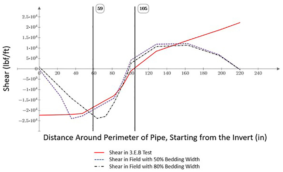
Shear versus perimeter length around a 120” equivalent arch pipe.
It was apparent that the previous Minnesota DOT designs had extended stirrups even further out than one wall thickness past where R3 and R1 intersect. In reviewing the designs for the previous arch pipe fill heights, it was found that a wider bedding width of 80 % had been assumed ( 8 ). It is likely this value was chosen because it roughly represents the location where the larger bottom radius of the pipe (R1) transitions into a much smaller radius at the sides of the pipe (R3). In discussions with Minnesota DOT, it was decided that with the relatively flat bottom surface of the arch pipe it would be logical to assume a wider bedding with a void near the outer bedding of the pipe. Thus, the pipes were redesigned assuming bedding support for 80 % of the bottom width of the pipe. The pipes were then evaluated for the same fill height, only with the assumption of a wider bedding. Thus, the soil load remained the same, and the total shear was the same. However, the wider bedding moved the location of maximum shear further out from the bottom middle of the pipe. With the new assumptions, the location of maximum shear occurred within the R3 radius (see Figure 7). Using an 80% bedding assumption, when stirrups are required, they should extend roughly halfway around the R3 radius.
As shown in Figure 8 the newer designs matched very closely with the previous designs used to establish the original Minnesota DOT fill height tables.

Shear versus perimeter length around an arch pipe for the earlier and recent Minnesota Department of Transportation designs.
Summary
Designs for reinforced concrete arch pipe were developed for the Minnesota DOT following the AASHTO LRFD Bridge Design Specifications. Much was learned with regard to the design of precast concrete arch pipe during the process of developing new Minnesota DOT design tables.
Very little research has been performed on reinforced concrete arch pipe in relationship to a design procedure corresponding to the anticipated loads and stresses on the pipe when installed in accordance with the Standard Installations used in AASHTO. Thus, the previous design method for reinforced concrete arch pipe was modified to accommodate the Standard Installations.
Modifying the previous AASHTO design method for reinforced concrete arch pipe into a form that follows the circular pipe nomenclature for the Standard Installations results in designs that are more conservative than the previous design method.
The reinforced concrete arch pipe for Minnesota DOT was designed to accommodate the worst cases of the loads and stresses in both the installed condition assuming a Type 3 Installation and the 3.E.B. apparatus at the plant
In many of the designs for Class IV arch pipe, stirrups are not required in the crown of the pipe for the field installation; however stirrups may be put in the pipe to pass the three-edge bearing test.
When field installations require stirrups, they are extended further along the perimeter of the pipe than is required for the three-edge bearing test. The assumptions made for the bedding support of the pipe have a major effect on how far out to extend the stirrups.
Footnotes
Author Contributions
The authors confirm contribution to the paper as follows: study conception and design: J. Beakley, R. Dvorak, and K. Western; data collection: J. Beakley and R. Dvorak; analysis and interpretation of results: J. Beakley, R. Dvorak, and K. Western; draft manuscript preparation: J. Beakley, R. Dvorak, and K. Western. All authors reviewed the results and approved the final version.
Declaration of Conflicting Interests
The author(s) declared no potential conflicts of interest with respect to the research, authorship, and/or publication of this article.
Funding
The author(s) received no financial support for the research, authorship, and/or publication of this article.