



Abstract
One common method for removing deteriorated coatings from steel bridges is abrasive blast cleaning. Although effective, abrasive blast cleaning can be hazardous to operators and must be conducted using expensive containment. One innovative solution to the hazardous nature and high expense of blast cleaning is laser ablation coating removal (LACR). LACR uses a high-energy laser, rather than conventional blasting, to remove the coating and has the potential to minimize operator hazards and eliminate the need for containment. The purpose of this study was to evaluate a continuous LACR system in relation to its coating removal effectiveness, industrial hygiene (IH), and effect on the steel substrate below the underlying coating. Coating removal and IH evaluation were performed on coated steel samples, including some with lead and other toxic metal coatings. LACR was also performed on bare steel, used to perform mechanical testing, such as tension, fatigue, hardness, and microstructural analysis to evaluate the effect of LACR on a steel substrate. In comparison to the pulsed LACR system evaluated in a previous study, the continuous LACR system was 2–27 times faster at removing most coatings, but it was unable to remove white coatings like the pulsed LACR system was able to do. IH evaluation showed that the continuous LACR system was likely to generate toxic metal fumes when ablating lead coatings, but this could possibly be minimized by designing an attached fume extraction system. Mechanical testing showed that the continuous LACR had no detrimental effects to the steel substrate.
Keywords
One of the most common methods of preventing corrosion on steel bridges in the United States is the use of coatings. Historically lead-based alkyd paint systems were used, though they were phased out in the 1980s, and now have typically been replaced with zinc-rich paint systems ( 1 ). Although the use of coatings for mitigating corrosion is effective, all coating systems slowly deteriorate and eventually fail after years of service and exposure to weathering and chlorides. This is especially common in aggressive environments, such as near salt water or at the end of a bridge beam under a leaking deck joint. In any case, when these coatings flake off the steel substrate, the failed coating must be removed, the surface must be properly prepared, and the steel substrate must be re-coated to maintain corrosion protection of a steel bridge.
One common method for removing deteriorated coatings on steel bridges is by abrasive blast cleaning. This method consists of forcing an abrasive blast medium, such as steel shot or grit, through air hoses using compressed air. The abrasive then removes the coating and exposes the underlying steel substrate. Although effective at removing coatings, this process can be hazardous to workers and the surrounding public, especially if the coating being removed contains lead or other toxic metals. To comply with current federal environmental regulations, abrasive blast cleaning of steel bridges is typically conducted inside containment structures to minimize public exposure to airborne coating particulates.
Although these containment structures do protect the surrounding public from exposure, they also have the potential to increase worker exposure to airborne contaminants within the containment. These containment structures can also have low visibility, leading to the potential for slip and fall injuries ( 2 ). All of these associated health risks make these containment structures quite expensive. As an example, Virginia Department of Transportation (VDOT) spends approximately $160 million per year on bridge maintenance, with approximately 10% of this cost going toward bridge coating maintenance ( 3 ). These costs include mobilization, traffic control, worker health and safety, environmental protection, surface preparation, containment, re-coating, and waste disposal of coatings removed ( 4 ).
One potential solution to minimize the costs and health hazards associated with abrasive blasting coatings inside containment is through using laser ablation coating removal (LACR). In general, LACR is a process that uses a high-energy laser to remove surface layers of a material. Although LACR has not traditionally been used for coating removal on steel bridges, it has been used in many other applications, including rust and coating removal on aerospace and marine structures, nuclear decontamination, and art and sculpture cleaning and refurbishing ( 4 ). It has been used for coating removal of prominent building structures, such as the U.S. Capitol Building, Philadelphia City Hall, and the Canadian Parliament building ( 4 ).
Because of LACR’s success in a wide range of applications, the Virginia Transportation Research Council (VTRC) and VDOT have begun investigating the use of LACR for coating removal on steel bridges. A VTRC/VDOT project completed in 2019 investigated the use of a pulsed laser and its effectiveness at coating removal ( 4 ). The pulsed laser used in this investigation works by sending nanosecond-length laser pulses at a surface. Therefore, the peak power output could be much higher than the average power output, depending on the laser peak waveform. When the laser contacts the coated surface, it removes the coating using heat and ablation, which then allows for capture of the removed coating material by a fume extraction system ( 5 ). The pulsed laser used in this project is capable of delivering an average power of 1 kW ( 6 ).
The project included both a laboratory and field demonstration of pulsed LACR. The laboratory demonstration consisted of removing coating from several retired VDOT bridges, metallurgical evaluations, mechanical testing, adhesion testing of a coating applied to the pulsed laser cleaned surface, and an industrial hygiene (IH) and environmental evaluation. The field evaluation consisted of using a pulsed LACR system to remove coating from a VDOT bridge and an IH evaluation during the process.
The project showed that the pulsed LACR was effective at removing all types of coatings evaluated in the project, including lead-based alkyd paints. The metallurgical evaluation and mechanical testing revealed that the pulsed LACR process caused no detrimental effects to the steel substrate. Microscopic evaluations showed that surface melting caused by LACR reached a depth of only approximately 0.04 mils. There were no adverse changes to the yield stress, tensile strength, ductility, fatigue performance, hardness, or steel chemistry. Adhesion testing on an epoxy binder coating applied to a pulse LACR surface showed satisfactory performance, though it was not consistently better than adhesion of the same coating on a grit-blasted surface. The field demonstration portion of the research revealed that the pulsed LACR system could easily remove coating from large, easily accessible, flat surfaces, but was relatively slow and had difficulty in removing coating in areas with tight geometry ( 4 ).
The IH and environmental evaluation concluded that pulsed LACR, fume extraction, and filtration system were effective at maintaining potential operator exposures below current Occupational Safety and Health Administration (OSHA) limits. This evaluation showed that when removing a lead-based coating, LACR reduced the operator lead and toxic metal exposure by approximately four orders of magnitude when compared with abrasive blasting and does not require containment structures like abrasive blasting ( 4 ). It also noted that waste from the LACR’s filtration system must be considered hazardous waste and requires appropriate personal protective equipment for disposal and removal of the filter ( 4 ).
Overall, the project showed the potential effectiveness of using a pulsed LACR system for removing coatings on steel bridges and demonstrated some of the cost and health benefits of the LACR system when compared with the traditional abrasive blasting method of coating removal. Therefore, the VTRC/VDOT wanted to evaluate other types of lasers to determine if they could provide faster coating removal or were able to remove coatings in tight spaces.
Purpose and Scope
The purpose of this project was to evaluate a continuous LACR device in relation to its coating removal effectiveness, effect on the steel substrate, and IH characteristics. A continuous laser, as opposed to a pulsed laser, works by delivering a continuous power output so that the average and peak output are similar. The continuous laser system used in this project is capable of delivering a power output up to 10 kW ( 7 ).
The scope of the project included VTRC/VDOT staff taking samples to the continuous LACR device manufacturer to observe and evaluate the coating removal process. Some samples were reserved for mechanical and metallographic testing, which was conducted at the VTRC and the University of Virginia. IH data were collected during coating removal and additional samples were sent to a laboratory for analysis.
Test Materials and Methods
Test Samples
Before traveling to the manufacturer of the continuous LACR system to observe the coating removal process, multiple types of steel samples with various types of coatings were procured from several sources. This was done to evaluate the LACR process on a wide range of coatings and dry film thicknesses. The types of coatings and coating thicknesses were all characterized before any coating removal. Table 1 shows a summary of the test sample names, sizes, coating types, topcoat colors, and the dry film thickness of the coating on each type of sample. Figure 1 shows photographs of each of the sample types.
Summary of Test Samples Used for Continuous Laser Ablation Coating Removal Evaluation

Note: FHWA = Federal Highway Administration; VDOT = Virginia Department of Transportation; Ep = Epoxy; Acr = Acrylic; IOZ = Inorganic Zinc; Zn = Zinc; Unk = Unknown; Vin = Vinyl; na = not applicable.

Photographs of test samples.
The samples referred to as “FHWA test plates” were procured from the Federal Highway Administration (FHWA) Turner-Fairbank Highway Research Center Corrosion Laboratory. Additional samples of the same type were used in the previous VTRC/VDOT project evaluating the use of the pulsed LACR system ( 4 ). All of these test plates had a three-coat system applied. The samples referred to as “VDOT test plates” were procured from the VDOT Materials Division coating research samples. These samples also had a three-coat system of many different types as noted in Table 1. Although the exact age of the coatings was unknown, it is estimated that these coatings were applied to the plates in the 1990s.
The samples referred to as “VDOT I-beams” were rolled steel beams that were taken from a retired bridge in the VDOT Lynchburg District. These samples were the oldest of the coated samples used in this project, as VDOT discontinued the use of lead-based coatings in the early 1980s. The sample referred to as “A36 steel plate” was a steel plate meeting the ASTM A36 (A36) specifications with no coating applied to it ( 8 ). This sample was used to evaluate the effect of the continuous LACR process on the steel substrate mechanical properties. Portions of this plate were subject to continuous laser ablation cleaning, whereas other portions were not, to serve as a baseline for the mechanical properties of the steel plate.
Observation of the LACR Process
VTRC and VDOT staff traveled to the manufacturer of the continuous laser system in January 2020 to observe the LACR process on each of the different sample types. LACR was applied to the samples at various power levels, offset distances between the laser and the sample being cleaned, number of passes, and travel speeds. The specific parameters applied to each sample tested will be noted when relevant. Visual observations were recorded by the VTRC and VDOT staff during the LACR process.
LACR was conducted both with the laser mounted to a robotic arm and used as a handheld device. Both setups are shown in Figure 2. When evaluating the coating removal on the FHWA and VDOT test plates, the continuous LACR system was mounted to the robotic arm and test plates were cleaned two at a time. LACR was conducted at various power levels and offset distances to vary the laser intensity. Power levels used included 4 kW, 6 kW, and 8 kW. Laser offset distances included 13.8” and 15.7”. LACR was applied in multiple passes until either the coating was removed or it became apparent that it could not be removed. The number of passes applied to each sample was recorded. Note that a standalone vacuum system is shown in Figure 2a. The continuous LACR system evaluated in this study did not have a built-in fume extraction system like the pulsed LACR system did evaluated in a previous study ( 4 ). Therefore, a standalone vacuum system was used to capture fumes from the LACR process.

Continuous laser ablation coating removal system used: (a) with a robotic arm or (b) as a handheld unit.
When evaluating coating removal on the VDOT I-beams, the LACR unit was held by an operator. Two different power levels were used during this process: 4 kW and 6 kW. Offset distance and number of passes were not recorded during this process as they could not be held constant because of the nature of operating the laser by hand versus having it mounted to a robotic arm.
IH Evaluation of LACR Process
The IH survey was conducted by VDOT Environmental Division personnel at the continuous laser manufacturer’s facility during the coating removal process. Personal and area concentrations of a variety of airborne metals, organics, and other thermal products of degradation were collected during the coating removal process. The survey was conducted in an open shop area while utilizing fixed and positional local exhaust ventilation. Pumps were pre- and post-calibrated for the analytes sampled with representative sampling media.
Table 2 provides a summary of the IH evaluation sample types, analytes, and the test methods used for evaluation. The test methods provided in the table refer to National Institute for Occupational Safety and Health (NIOSH), OSHA, and Environmental Protection Agency (EPA) standards. In general, four types of samples were collected: metal fume, products of thermal degradation, toxic characteristic leaching, and lead wipe.
Summary of Industrial Health Evaluation Conducted on Continuous Laser Ablation Coating Removal System

Note: HDI = hexamethylene diisocyanate; TDI = toluene diisocyanate; MDI = methylene bisphenyl isocyanate; NIOSH = National Institute for Occupational Safety and Health; OSHA = Occupational Safety and Health Administration; EPA = Environmental Protection Agency.
Metal fume samples were collected using 37 mm mixed cellulose ester filters. These samples were collected as area samples positioned at the VDOT minimum controlled area boundary, immediately adjacent to the laser face, and as personal samples collected in the personal breathing zone during handheld operation.
Other products of thermal degradation samples were collected via organic badge vapor monitors or sorbent tubes. These samples were collected 6–12 in. from the head of the laser when operated in the robotic arm to mimic a personal sample. A badge vapor monitor was worn by the operator during handheld operation.
Toxic characteristic leaching procedure testing was conducted on particulate taken from the standalone vacuum system that was captured using high-efficiency particulate air (HEPA) filters. These filters were freshly installed for capturing data during the handheld laser operation on the VDOT I-beams.
Lead wipe samples were taken from cleaned surfaces of the VDOT I-beams after the LACR process.
Tension Testing of Steel Substrate
The LACR process was applied using the robotic arm in different power levels to different regions of the A36 steel plate. One region of the plate was subject to the continuous laser with a power of 6 kW, and another region of the plate was subject to a power of 4 kW. A third region of the plate was not subjected to the laser at all to serve as a baseline. This portion of the plate is referred to as “base metal.” In cases where the laser was applied, the laser offset distance was held constant at 15.7 in. Five passes of the laser were applied to both the top and bottom of the plate for each power level.
Six tension samples were machined from the A36 steel plate subject to each of the laser power levels: base metal, 4 kW, and 6 kW. All of the tension samples were machined according to the requirements for sheet-type specimens in ASTM E8 ( 9 ). All 18 of these samples were tested in a servo-hydraulic controlled uniaxial test frame with a 55-kip capacity actuator. Tension tests were conducted under the displacement controlled loading rates specified in ASTM E8. Strain was recorded for each test using a laser extensometer. Load and displacement data were recorded using the load cell and linear variable differential transducer from the load frame. Results were compared with each other and with the ASTM A36 steel plate requirements.
Fatigue Testing of Steel Substrate
Fatigue tests were also conducted on the A36 steel plate to determine whether different LACR power levels caused a change in the fatigue performance of the steel plate because of a potential heat-affected zone. Similar to the tension tests, fatigue tests were conducted on portions of the A36 steel plate subject to all three different laser power levels: base metal, 4 kW, and 6 kW. These fatigue samples were machined from the A36 steel plate to meet the requirements for sheet-type specimens in ASTM E8. Six fatigue tests were conducted on the 4 kW and 6 kW samples. Only two fatigue tests were conducted on the base metal because of the limited amount of A36 steel plate available, and because base metal fatigue is well understood and is considered a fatigue detail category A in the AASHTO LRFD Bridge Design Specifications ( 10 ).
All 14 fatigue tests were cycled under constant amplitude loading in the same load frame as used for the tension tests. Stress ranges were selected to maintain elastic behavior in the test specimens. The first fatigue test was conducted on a base metal sample and was cycled under a constant stress range of 26 kips per square inch (ksi). The remaining fatigue tests were cycled under a stress range of 32 ksi. Rationale for increasing the stress range after the first fatigue test will be discussed in the Results section. For all fatigue tests, the minimum stress range was 0.25 ksi. The load and number of cycles were recorded during testing, and the results were compared with the fatigue design specifications in the AASHTO LRFD Bridge Design Specifications ( 10 ).
Hardness Testing of Steel Substrate
Similar to the tension and fatigue tests, hardness tests were conducted on portions of the A36 steel plate not exposed to LACR and those exposed to LACR at 4 kW and 6 kW power levels. Five individual hardness tests were performed on each type of surface using the Rockwell B scale ( 11 ).
Microstructural Evaluation of Steel Substrate
Similar to the other mechanical tests, a microstructural evaluation of the steel substrate was conducted on portions of the A36 steel plate not exposed to LACR and those exposed to LACR at 4 kW and 6 kW power levels. Test samples were ground, polished, and etched using a 5% nital etchant following the requirements of Etchant #74 in ASTM E407 ( 12 ). Etching is necessary because it preferentially affects different features of the steel to make its microstructure visible under a microscope. Nital is a commonly used, general-purpose etchant to reveal ferrite grain boundaries. After the etchant was applied to the samples, they were examined under an optical microscope using bright-field illumination.
In addition to examining the microstructure, the fracture surfaces of the tension samples were viewed under a scanning electron microscope (SEM). SEM evaluation was used to determine if the fracture surfaces of the steel samples subject to different LACR power levels appear the same in relation to the ductile or brittle fracture behavior.
Results and Discussion
Observation of LACR Process
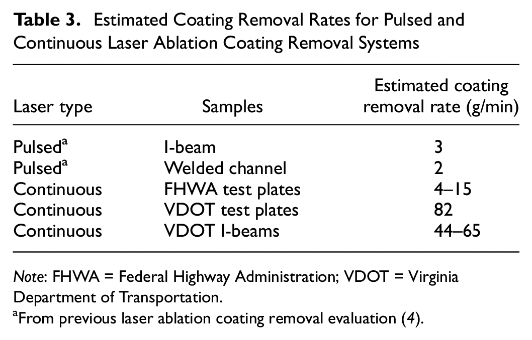
The coating removal rates for the continuous LACR system were based on the estimated area of coating removed, dry film thickness of the coatings on the samples, estimated unit weight of coating, and laser arc time required to remove the coating. These coating removal rates for each of the different sample types used in this evaluation are shown in Table 3. The table also shows the estimated coating removal rates of the previous pulsed LACR system evaluation ( 4 ).
Estimated Coating Removal Rates for Pulsed and Continuous Laser Ablation Coating Removal Systems
Note: FHWA = Federal Highway Administration; VDOT = Virginia Department of Transportation.
From previous laser ablation coating removal evaluation ( 4 ).
In comparing the coating removal rates between the two LACR systems, it is clear that the continuous laser is much faster at removing coating, with a relative rate approximately 2–27 times faster than the pulsed laser system, except when removing white coatings as will be discussed. The large variation in the comparison of removal rates for the different LACR systems is dependent on the coating type, laser power level, offset distance, and mode of laser operation (either robotic arm or handheld).
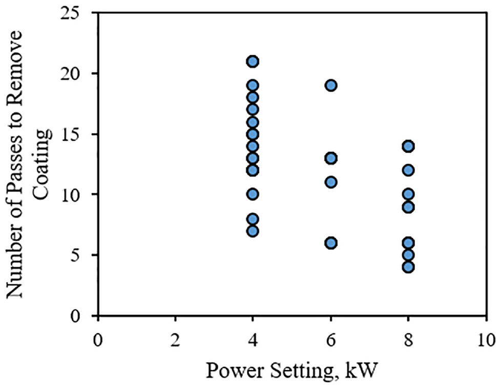
Coating removal was also compared in relation to the number of passes required to completely remove the coating and the continuous LACR power level used. Only the FHWA test plate and VDOT test plate samples were used in this comparison as these samples were cleaned with the laser system mounted to the robotic arm; only samples cleaned using the robotic arm were used for this comparison as the number of passes could not be accurately counted during handheld laser operation. Results of this comparison are shown in Figure 3. This figure shows that as the power level was increased, fewer passes were required to remove the coatings. Note that variability does exist since the samples used for this data included coatings with various colors and thicknesses.
Plot of number of passes required to remove coating versus power level for continuous laser ablation coating removal mounted to robotic arm.
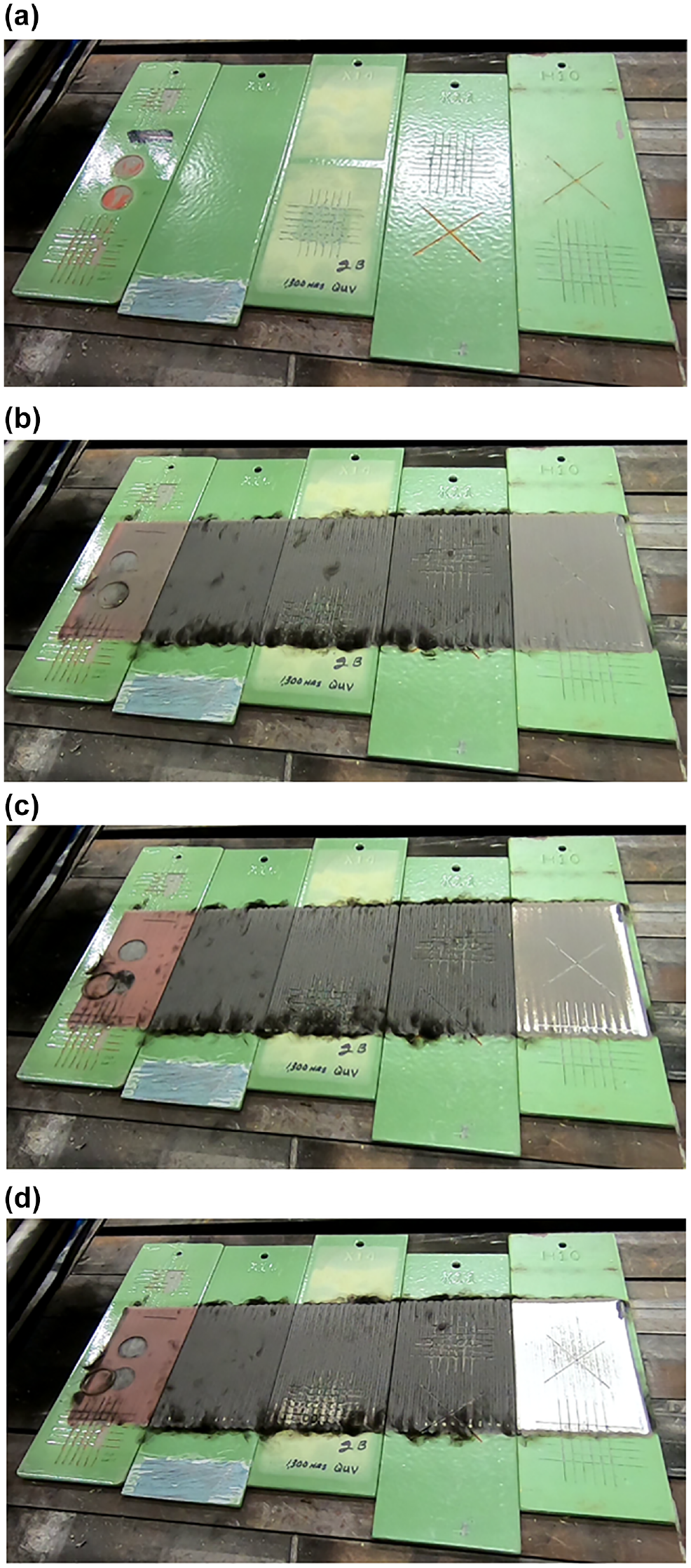
As previously mentioned, one important observation noted during coating removal of the VDOT test plates was that the continuous LACR had difficulty removing white-colored coatings. This was especially apparent during the LACR process on green topcoated VDOT test plates. During the first pass of LACR, the laser was able to easily remove the green topcoat, which revealed a white intermediate coat underneath. After the topcoat was removed, the LACR process was continued; however, the laser was not able to remove any of the white coating no matter how many passes were attempted. This process is demonstrated in Figure 4. This figure shows photographs of the initial condition of these green topcoated VDOT test plates and their condition after one, two, and three passes of LACR. Note that in Figure 4d, the white intermediate coat remains visible and was not able to be removed after additional passes. The pulsed LACR system evaluated by VTRC/VDOT in a previous research study was able to successfully remove all coating colors ( 4 ).
Continuous laser ablation coating removal process on green topcoated Virginia Department of Transportation test plates: (a) in initial condition, (b) after one pass, (c) after two passes, and (d) after three passes.
Another important observation was made during handheld operation of the LACR unit on the VDOT I-beam samples. During this process, a large amount of fumes present was not collected by the standalone vacuum being used. As noted in the introduction, extracting the fumes generated during the LACR process is important to ensure worker safety. Unlike the pulsed laser system evaluated previously, the continuous LACR system in this evaluation did not have a built-in fume extraction system on the laser unit so a standalone vacuum system was used instead ( 4 ). Figure 5 shows the continuous laser system in use on a VDOT I-beam sample with the standalone vacuum. As shown in the figure, when the laser system was moved away from the vacuum, the vacuum system was not able to capture all of the fumes being generated.

Fumes not captured by standalone vacuum during handheld operation of continuous LACR unit on VDOT I-beams.
IH Evaluation of LACR Process
IH sample results were compared with the OSHA Permissible Exposure Limits and OSHA Action Levels as outlined in contaminant specific regulation or OSHA Subpart Z, “Toxic and Hazardous Substances,” when applicable. Where a current regulatory limit does not currently exist, sample results were compared with current IH best practice recommendations.
IH survey monitoring results were below laboratory detection limits for all organics and expected products of thermal degradation. Metals sample results were variable but showed that the greatest airborne concentrations were found during handheld removal of the lead alkyd primer from the VDOT I-beams. Leaded fume samples from the handheld LACR operation exceeded the OSHA regulatory limits by approximately 1.5–15 times. Note that the pulsed laser system investigated by VTRC/VDOT in a previous study met all IH regulations according to VDOT’s special provision on LACR use ( 4 ). However, the pulsed laser in that study had a built-in fume extraction nozzle attached to a three-stage filtration system which had been designed specifically for use with the pulsed laser, whereas the continuous laser in this study used a standalone vacuum system. It is likely that further engineering controls would be required for this continuous laser system before use on VDOT projects.
Removal of coatings from FHWA test plates and VDOT test plates indicated airborne metal concentrations slightly above the level of detection for some analytes, and it is unlikely that further engineering controls would be required during removal operations of zinc-based coating systems in environments with adequate ventilation. There did not appear to be any notable differences in IH results when considering different laser powers, offset distances, or laser speed of travel.
Leaded dust levels on the VDOT I-beams indicated that surfaces after LACR contained lead at a level that has the potential to contribute to worker exposure following coating removal. Therefore, careful handling of previously lead-coated beams after LACR is imperative; wearing of gloves and handwashing can aid in this process.
The waste generated during the continuous LACR process for all of the samples was minimal, fitting within a five-gallon waste-bin. The filters from the standalone vacuum system constituted the bulk of the material produced. Analysis of this waste indicated that the debris was a hazardous waste requiring appropriate disposal.
Tension Testing of Steel Substrate
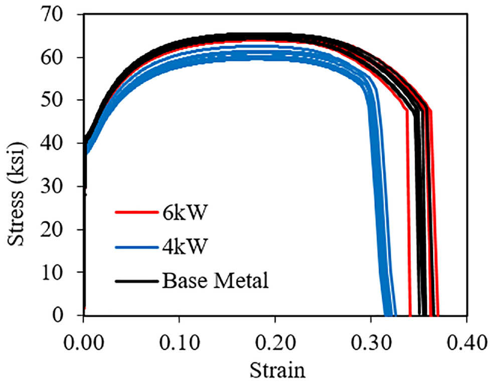
Stress versus strain curves were developed for each of the tension test samples and are shown in Figure 6. As seen in the figure, test samples subject to each laser power level (base metal, 4 kW, and 6 kW) produced repeatable results. However, there are some noticeable differences between the different power levels. The base metal and 6 kW samples appear to have nearly identical behavior, whereas the curves for the 4 kW samples clearly fall below the other two.
Stress versus strain curves for tension samples subject to continuous laser ablation coating removal.
It seems counterintuitive that the 4 kW samples would behave differently than the other two samples, as the LACR power level was in between the base metal (no LACR applied) and the 6 kW samples. It is possible this difference in behavior is not caused by the laser power level, and is instead the result of a mislabeling error when the tension samples were cut out of the A36 steel at the machine shop. This error is possible because when the all of the mechanical test samples and the skeleton A36 steel plate were returned to VTRC from the machine shop, it was readily apparent that the samples were not cut out of the A36 steel plate in the exact desired locations that were indicated in the drawing provided to the machine shop. VTRC researchers were able to confirm that the samples were cut from the three distinct regions of the A36 steel plate subject to each power level, but could not completely confirm that the samples were cut from the region by which they were labeled.
Nevertheless, even though the samples labeled as 4 kW did present different tensile behavior than the base metal and 6 kW samples, all of the samples easily met the tensile requirements of ASTM A36 steel plate, including for yield stress, tensile strength, and elongation. Therefore, the test results showed that the continuous laser did not have any detrimental effects on the tensile properties of the A36 steel plate for the laser power level, offset distance, and number of passes used during the LACR process.
Fatigue Testing of Steel Substrate
Table 4 shows the results of the fatigue tests conducted on the A36 steel plate subject to continuous LACR at different power levels. As the table shows, none of the fatigue samples failed as a result of fatigue and all were considered runouts, which were defined as specimens which reached a predetermined cycle count without developing a fatigue crack. The first test, denoted as base metal—1, was considered a runout at 10 million cycles, whereas the remaining tests were considered runouts at 5 million cycles. The definition for a runout was changed after the first specimen was tested to condense the amount of time required to conduct all of the fatigue tests.
Fatigue Test Results on A36 Steel Plate Subject to Continuous Laser Ablation Coating Removal
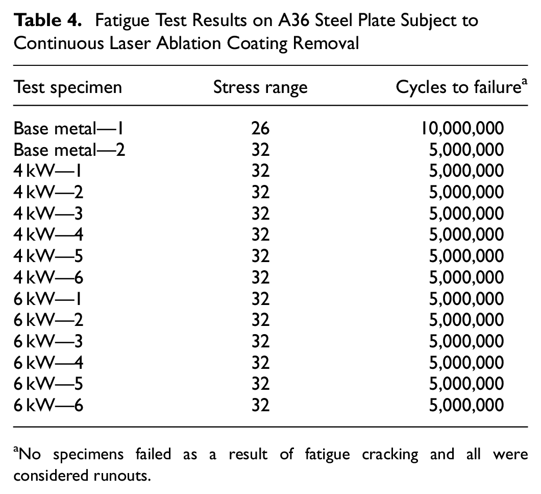
No specimens failed as a result of fatigue cracking and all were considered runouts.
Figure 7 shows the fatigue data plotted on a typical stress range versus number of cycles (S-N) plot, including the typical AASHTO fatigue design curves. Runouts are denoted with a forward-pointing arrow. As all of the fatigue tests were considered runouts, all of the data points are stacked on top of each other aside from the first fatigue tests conducted, base metal—1. The test results clearly show that the samples subject to the continuous LACR at 4 kW and 6 kW power levels performed better than the AASHTO fatigue detail category A, which represents base metal. This shows that these power levels of continuous LACR did not detrimentally affect the fatigue performance of the steel substrate.
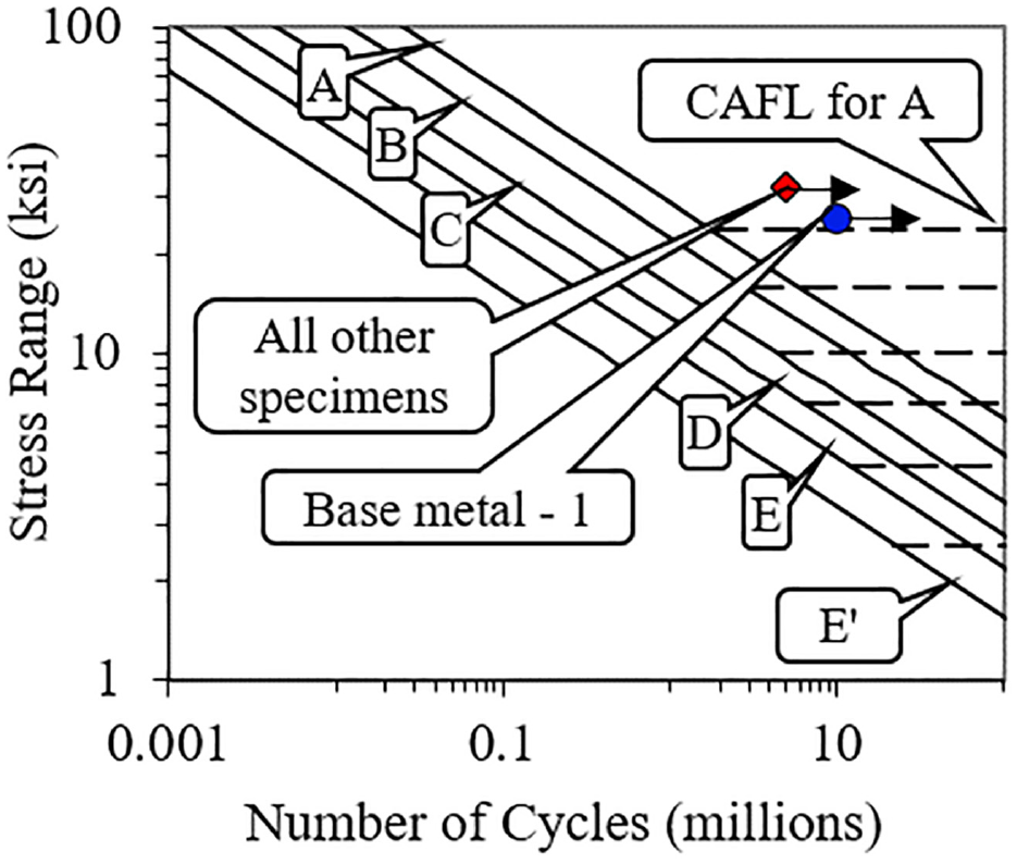
S-N plot for fatigue tests subject to continuous laser ablation coating removal at various power levels. Note: CAFL = constant amplitude fatigue limit; A-E′ letters refer to fatigue detail categories in AASHTO LRFD Bridge Design Specifications.
Hardness Testing of Steel Substrate
Figure 8 shows a box and whisker plot of the hardness test results conducted on the A36 steel plate subject to different continuous LACR power levels, including tests conducted on base metal without LACR. There are no hardness specifications in the ASTM A36 steel standard so test results were compared relative to one another. As shown in the plot, the hardness results for base metal and 4 kW LACR surfaces appear similar, suggesting that continuous LACR at a power of 4 kW did not alter the surface hardness at all. The hardness results for the 6 kW LACR surface appear to be slightly less than the base metal and 4 kW LACR surfaces, indicating the 6 kW power level may have slightly affected the hardness of the steel. However, when these data are combined with the tension and fatigue data, it does not appear that this slight reduction in hardness had any detrimental effect to the steel substrate.
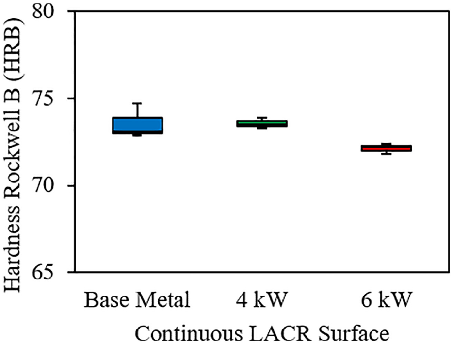
Box and whisker plot of hardness results on laser ablation coating removal surfaces subject to different power levels.
Microstructural Evaluation of Steel Substrate
Figure 9 shows micrographs from the optical microscope evaluation of the A36 steel plate subject to no LACR and subject to LACR at both 4 kW and 6 kW power levels. All of the micrographs in the figure were taken near the edge of the steel plate to evaluate if changes in the microstructure were present near the surface. Figure 9a serves as comparison for the other two micrographs as the steel in this micrograph was not subject to LACR. When examining the microstructure of the 4 kW and 6 kW samples, it is clear that the microstructures do not change significantly from the edge of the plate into each plate’s thickness. This indicates that the LACR process at both power levels did not leave a heat-affected zone, which was also demonstrated during the tension and fatigue testing. Although the typical grain size of the base metal sample does appear to be slightly larger than the 4 kW and 6 kW samples, this does not appear to have a detrimental effect, as shown by the tension and fatigue test results.
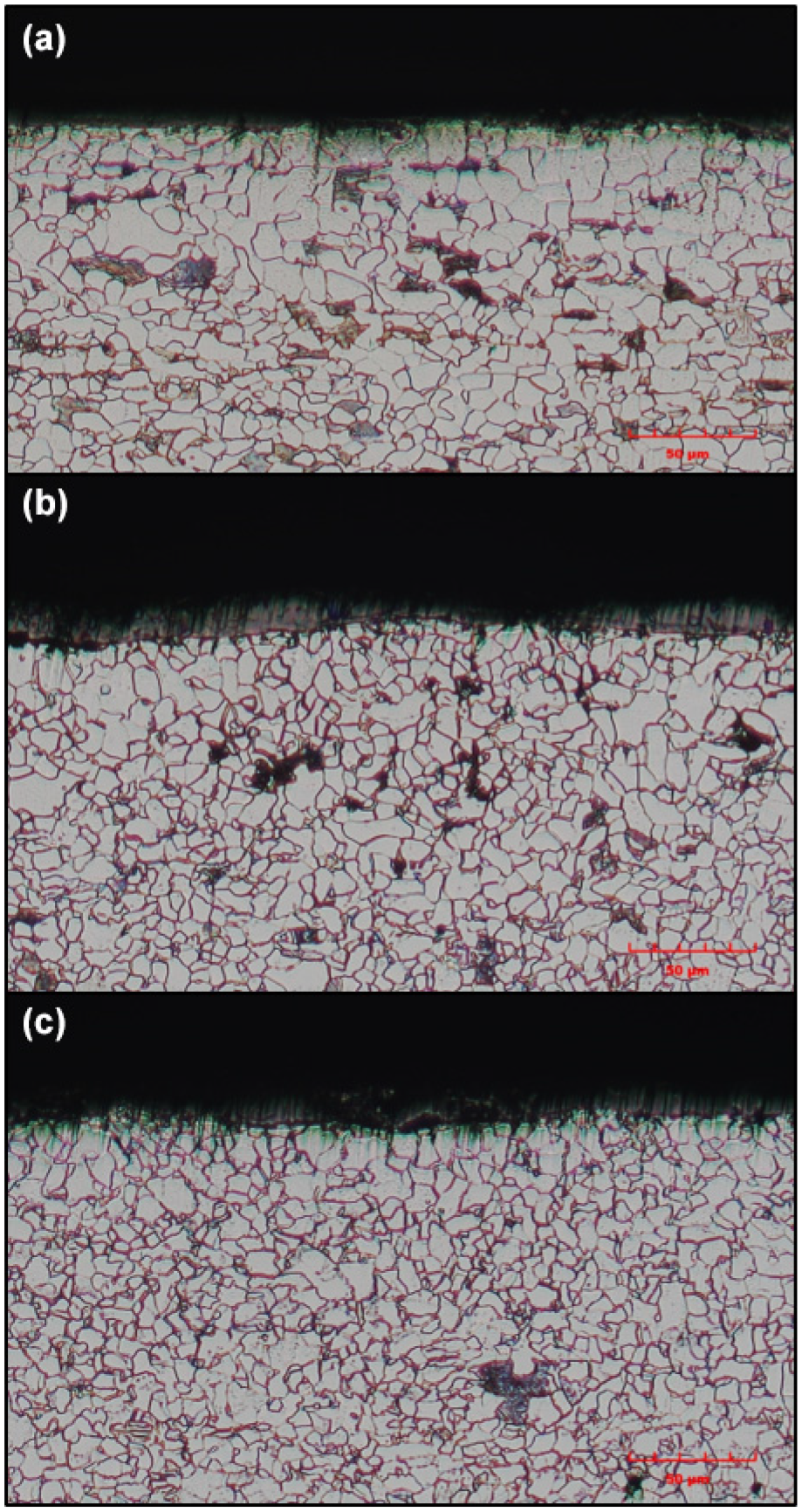
Microstructure of A36 steel plate subject to: (a) no laser ablation coating removal (LACR)—base metal, (b) LACR at 4 kW power, and (c) LACR at 6 kW power, viewed under optical microscope at 1000× magnification with 5% nital etch.
Figure 10 shows images of the fracture surfaces of the tension test samples viewed under an SEM. Similar to the microstructure results, the fracture surface of the base metal A36 steel tension sample (shown in Figure 10a) was used as the baseline for comparison with the 4 kW and 6 kW samples. The fracture surfaces of all images indicate that each sample type possessed sufficient ductility, shown by the microvoid coalescence, or small circles indicative of a cup and cone ductile fracture. When comparing the 4 kW and 6 kW fracture surfaces with the base metal fracture surface, the images look relatively similar. Overall, the fracture surface evaluation indicated that both power levels of LACR did not negatively affect the ductility of the A36 steel plate.
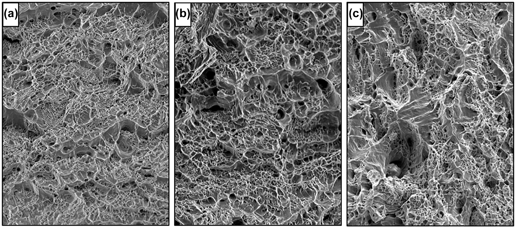
Fracture surface of: (a) base metal, (b) 4 kW, and (c) 6 kW tension test samples viewed under scanning electron microscope at 1000× magnification.
Conclusions
LACR has the potential to minimize operator hazards and eliminate the need for containment during steel bridge coating removal. A continuous LACR system was evaluated in this study and the coating removal, IH, and mechanical testing results were compared with those from a previous study using a pulsed LACR system. Using a greater power setting on the continuous laser system generally resulted in fewer passes of LACR required to remove a coating. Except for white coatings, the continuous LACR system evaluated was able to remove coatings at a rate approximately 2–27 times faster than a pulsed laser system evaluated in a previous study. The large variation in coating removal rates is dependent on coating type, coating thickness, laser power level, and laser offset distance. The continuous LACR system evaluated was not able to successfully remove white coatings. A pulsed LACR system evaluated in a previous study was able to successfully remove all coating colors.
The IH results showed that the continuous LACR system is likely to generate toxic metal fumes above regulatory limits and that further controls are necessary to reduce metal fumes below regulatory limits when ablating leaded and other toxic metal-containing coatings. One potential control solution is a properly designed fume extraction system in combination with the continuous laser. The pulsed LACR system evaluated in a previous study had a built-in fume extraction system which was effective at maintaining potential operator exposures below current OSHA limits. IH sampling also showed the minimal waste captured through the standalone vacuum system is likely to be a hazardous waste when the coating contains toxic metals.
Mechanical testing showed that the continuous laser system used at power levels of 4 kW and 6 kW did not exhibit any detrimental effects to the steel substrate in relation to tensile properties, fatigue, ductility, or microstructure.
Footnotes
Acknowledgements
The authors would like to recognize the support and assistance of SurClean, VDOT’s Environmental Division, VDOT’s Materials Division, VDOT’s Structure and Bridge Division, and VTRC. Specifically, thanks are due to Don and Susan Sprentall of SurClean; C. Wayne Fleming, Adam Matteo, Jeff Milton, and David Wilson of VDOT; and Arthur “Bill” Ordel of VTRC.
Author Contributions
The authors confirm contribution to the paper as follows: study conception and design: J. Provines, S. Sharp, and R. Rickard; data collection: J. Provines, S. Sharp, and R. Rickard; analysis and interpretation of results: J. Provines, S. Sharp, and R. Rickard; draft manuscript preparation: J. Provines, S. Sharp, and R. Rickard. All authors reviewed the results and approved the final version of the manuscript.
Declaration of Conflicting Interests
The author(s) declared no potential conflicts of interest with respect to the research, authorship, and/or publication of this article.
Funding
Funding for this research was provided by VDOT.
