
Abstract
Unmanned aerial vehicles (UAVs) have transitioned from a futuristic research concept to becoming a reality for practical, safe, cost-effective bridge inspections. Several studies have used UAVs to capture images from bridges and infrastructure to assess their condition. However, measuring the dynamic responses of bridges using a UAV involves the integration of UAV, sensors, and the use of dynamic equations. Measurement of dynamic transverse displacement especially is a difficult task in the field given the actual constraints of bridges, flights, and sensing under loading events. If transverse displacements could be measured easily, bridge owners could prioritize maintenance operations more cost-effectively by selecting to repair those bridges that move the most under trains. This paper discusses new requirements and solutions for fabricating an enhanced UAV to obtain dynamic transverse displacement benefiting from experiences gained from several field tests. This work follows the regulations of railroad bridge inspection guidelines and considers the aspects for an implementable system in its development. The paper first introduces the preliminary system that has been developed to this end and discusses potential improvements to this system that are identified through multiple field tests. The preliminary UAV system was developed using an algorithm combining the signals from sensors mounted on the UAV to measure dynamic displacements. This paper explains the step-by-step improvement of the existing system which resulted in a successful field test on a real bridge. Subsequently, some modifications and enhancements for the algorithm are proposed which are compatible with the new system data.
Keywords
According to the American Society of Civil Engineers’ 2021 infrastructure report card, the grade of the U.S. infrastructure is C– ( 1 ). The railway system in the U.S.A. is very critical for the country’s economy, carrying 40% of the total freight in the country ( 2 ). Almost half of the railway bridges in the U.S.A. are over 100 years old and need regular inspections to stay operatable or in-service ( 3 ). Traditionally, LVDTs, linear variable differential transformer accelerometers, and wireless smart sensors (WSS) ( 4 – 6 ) are used to assess the condition of railway bridges. To use these sensors, inspectors need to climb onto the bridge and attach the sensor to the structure, which is risky and requires closure to traffic or additional tools such as snooper trucks or scaffolds for sensor attachments.
Besides the traditional bridge inspection methods, in recent years the use of UAVs for bridge inspections has been recognized as a promising alternative method ( 7 , 8 ). There are several proposed UAV research solutions to monitor infrastructure. Because of their affordable cost and accessibility, UAVs have been widely used for infrastructure monitoring with different purposes and for measuring various types of responses ( 9 ). Dorafshan et al. ( 10 ) used a camera attached to a UAV to monitor the condition of a bridge; Seo et al. ( 11 ) captured images of a concrete bridge and compared the images over time to detect the concrete deficiency. Additionally, Xu and Turkan ( 12 ) captured images from a steel bridge with a camera mounted on a UAV to detect corrosion on the bridge using the images. Even though these studies used a camera on a UAV, they still performed an image-based assessment, and they ignored the dynamic responses of the structure or the need to obtain the displacement values.
In recent years, a few researchers have used cameras on UAVs to obtain dynamic displacement values from structures. Jalinoos et al. ( 13 ) used a UAV enhanced with a camera for evaluation of dynamic movement of a mocked-up bridge. Additionally, Yoon et al. ( 14 ) measured simulated vertical dynamic displacement of a bridge using a camera on a UAV and Khadka et al. ( 15 ) used a UAV camera system to obtain the dynamic measurements from a wind turbine. However, these studies and methods were tested in laboratory environments and the performance of their systems and the challenges imposed by the varying environmental factors were not tested. Therefore, there is still a need for improvement of these technologies and methods to implement and transfer them to real field applications. In particular, cameras lack the capability of obtaining the out-of-plane component of the displacement and it is thus always assumed that the displacement occurs on a plane surface and the third dimension is unchanged.
There have been some efforts by the authors’ team ( 16 , 17 ) to use Laser Doppler Vibrometer (LDV) to address this limitation. That system was not fully implementable in the field, however, as it was too expensive for railroad managers to adopt and the system was not untethered and lacked the pseudo-static component of the displacement. Following that, the same researchers ( 18 ) made efforts to create a system called New Aerial System with Intelligent Measurement Integration (NASIMI) which not only can obtain the total dynamic transverse displacement component but is also affordable and implementable. The proposed system was tested in the field and its limitations were identified, which led to generating the enhanced system with higher capabilities which is called NASIMI II, following the name of the first version of the system. Dynamic transverse displacement under loading of railroad bridges can help managers to make objective decisions on prioritizing the repairs of their inventory or decreasing the speed of trains in critical locations to increase the safety of their operations. This study develops and enhances a UAV system interconnected with a methodology toward dynamic transverse displacement measurement on a real bridge. The proposed methodology combines the data from sensors of different natures to obtain a non-contact measurement from the structure. The system in this study is the first prototype of a ready-to-use low-cost system for dynamic transverse displacement measurement on a real bridge. This paper first gives a summary of the features of the preliminary UAV system that was developed in controlled laboratory experiments, NASIMI, and then discusses the considerations and steps for fabricating NASIMI II. Finally, it introduces the algorithm that can use the data collected from NASIMI II to obtain accurate displacement. This approach can be used as an alternative method to complement the existing inspection methods of the railroad bridges including but not limited to an assessment by trained inspectors in the field touching the structure or using contact-based measurement traditional sensors.
Preliminary System
A preliminary UAV system, NASIMI, was developed to measure the dynamic displacement of a moving surface using a UAV flying beside it. NASIMI was designed with a combination of low-cost sensing and data acquisition (DAQ) system to collect data from a camera and a single point time of flight laser mounted on a drone (UAV). A DJI Matrice 600 Pro UAV was selected for NASIMI. The proposed system measured the relative displacement between the moving surface and the hovering UAV using a laser. Subsequently, researchers measured and compensated the hovering of the laser on the UAV using a monocular camera which filmed a ground base target. The laser measurements were corrected in two phases: translational motion correction using computer vision and rotational motion correction integrating computer vision with laser measurement using signal processing. On the other hand, the response of the railroad bridge to freight loading was simulated in experiments using data collected in the field ( 19 ). The team processed the data with a computer vision and signal correcting algorithm designed for this system and measured the dynamic transverse displacement of a moving object in a non-contact way. During the design of NASIMI, the team conducted several field-based and laboratory tests to evaluate the performance of the system and identify the aspects that need to be improved or modified for a more comprehensive system. Benefiting from the information and lessons learnt from various field tests, the researchers realized the potential and the limitations of NASIMI for railroad bridge applications and designed NASIMI II with a modified methodology. Table 1 lists some of the experiments conducted by the team during the improvement of the first system (NASIMI). It is worth mentioning that the team conducted more tests than are listed in the table with the purpose of understanding environmental effects on the operations. The tests were mostly conducted at Balloon Fiesta Park located in Albuquerque, NM. Figure 1 shows NASIMI flying in Balloon Fiesta Park.
Details of Field Experiments with NASIMI
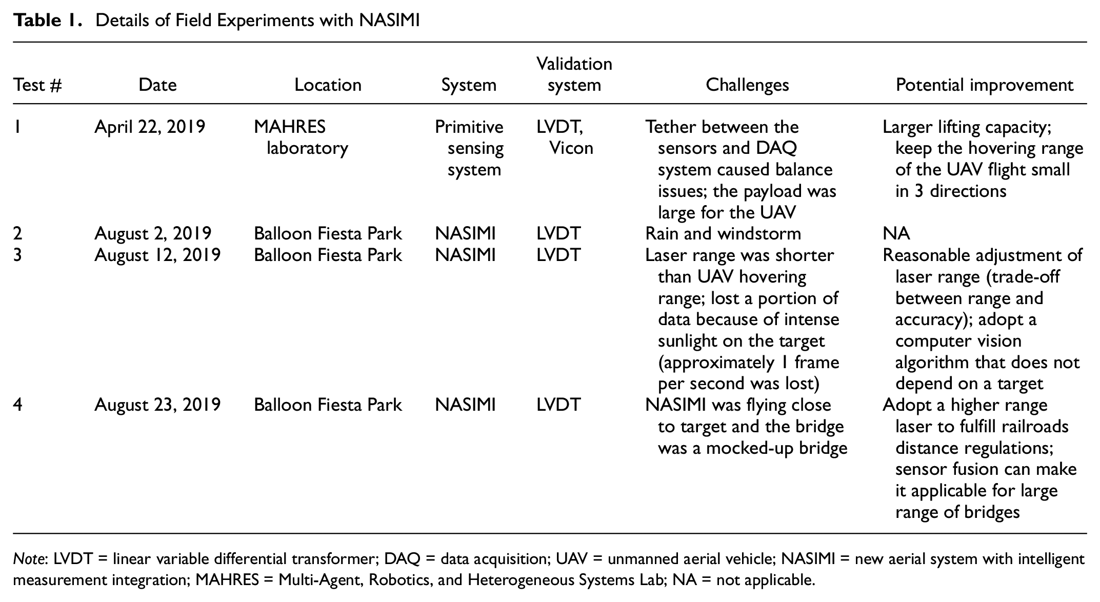
Note: LVDT = linear variable differential transformer; DAQ = data acquisition; UAV = unmanned aerial vehicle; NASIMI = new aerial system with intelligent measurement integration; MAHRES = Multi-Agent, Robotics, and Heterogeneous Systems Lab; NA = not applicable.

Unmanned aerial vehicle experiment with new aerial system with intelligent measurement integration (NASIMI), test #4.
Evaluation of NASIMI
Field tests with NASIMI were a proof-of-concept for the method and the performance of the first system. NASIMI was successful in measuring the non-contact dynamic transverse displacement but still could be upgraded using the lessons learnt from field tests. The researchers decided to upgrade the existing NASIMI for phase II, creating a more improved system replacing the sensors with more capable sensors to improve both the hardware and the algorithm and achieve higher displacement accuracy.
The potential and achievements of the NASIMI are as follows:
NASIMI is a low-cost, low-weight enhanced UAV–laser system.
The system can collect data from a moving structure in a non-contact and untethered way.
It can measure total dynamic transverse displacement, which includes dynamic and pseudo-static components.
The potential improvements for NASIMI and forming NASIMI II are listed as follows:
NASIMI can collect data within an approximate range of 1 m which is too close to be permitted for railroad bridge operations.
NASIMI is accurate enough for the displacement monitoring of trestle railroad bridges which experience larger peak displacement values under train crossing events but needs improvement to measure the bridges and other structures with small displacements.
Methodology and the New System: Design of NASIMI II
Hardware Considerations
Laser
As mentioned in Table 1, one of the challenges that the team faced in the field test was related to the appropriate adjustment of the laser range. To develop a cost-efficient system, the data acquisition system of the laser on NASIMI was fabricated using an Arduino board. Arduino microcontrollers have an ADC, analog-to-digital converter, value of 1,024 which means that the developed DAQ system can obtain the signal of a laser with a range of 800 mm with a precision of (800/1023 = 0.78 mm). This feature causes a trade-off between the optimum laser range and desired signal accuracy. In the second field test conducted with NASIMI, test number 3, the range of the laser was designed to be 300 mm, which caused a large amount of missing data where the drone was flying outside of the specified range. Figure 2a shows the test that was conducted in the field and Figure 2b shows the LVDT, laser, and proceed or post-processed camera data in the camera’s X coordinate which corresponds to the direction of laser light. Horizontal lines in the laser signal represent the moments when the laser data were missed.
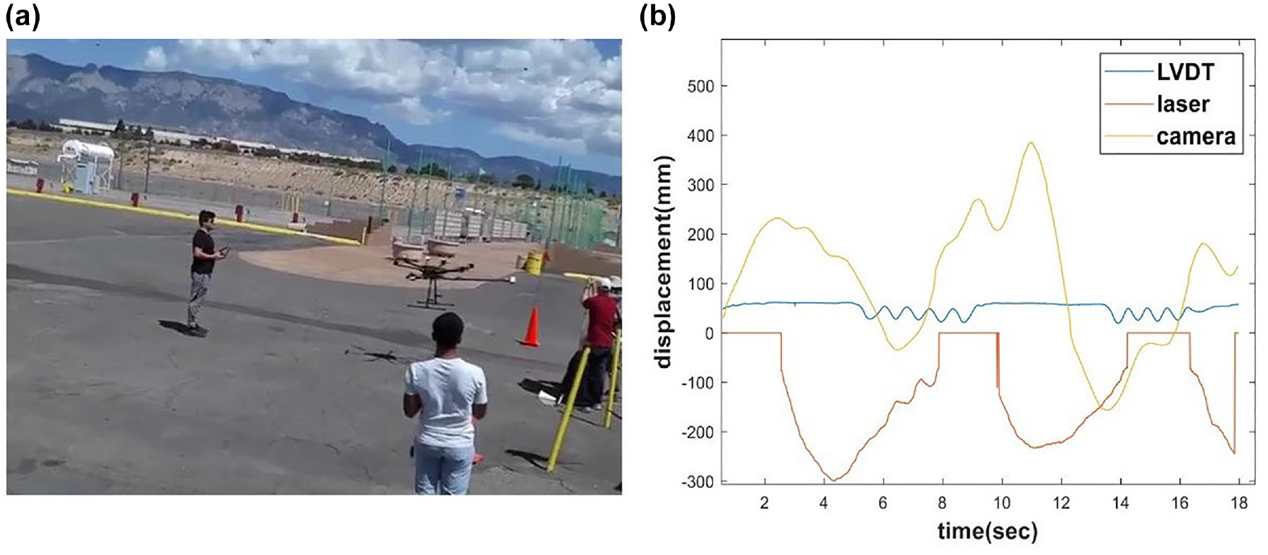
Experiment in Balloon Fiesta Park: (a) filming of the unmanned aerial vehicle (UAV) experiment from a different UAV, and (b) LVDT, laser, and camera data of the experiment.
Figure 2b shows that the laser data were not recorded when the hovering range of the laser was higher than 300 mm. Consequently the research team decided to use the full range of the laser with a slightly lower accuracy to do future tests.
After test number 4, the team shared the results with railroad bridge experts and managers. According to their feedback, the performance of the system is acceptable for in-field operations, especially the trestle railroad bridges which experience higher peak displacement under dynamic loading. However, the experts suggested looking for means of increasing the distance between the UAV and the surface of the moving structure. According to railroad regulations, drones (UAVs) should fly at a distance greater than 6 ft from the surface of interest. To address this issue, the research team looked for a laser with higher range displacement measurement specification and selected Keyence IL-2000. This laser has a reference distance of 2,000 mm, measurement range of ±1000 mm, and accuracy of 1 mm. The new laser was slightly heavier than the IL-600 which was used on NASIMI. However, a new case was made using a 3D printer to place the counterweight and hold the balance of the UAV while flying. As mentioned before, the Arduino based data logger has 1,024 ADC values, which is smaller than the measurement range of the laser (2,000 mm). This means that the Arduino based data logger can have a precision of 1.95 mm unless it is upgraded. Therefore, the researchers used an additional component called Adafruit ADS1115 16-bit ADC board. This component enables the designed DAQ system to collect data with higher resolution and convert the 10-bit microcontroller to a 16-bit microcontroller. Figure 3 shows the new laser and the added component to enhance the data logger.

Upgraded laser system: (a) New higher range laser head, Keyence-IL2000 and (b) Adafruit ADS1115 16-bit ADC (analog-to-digital converter) board.
Inertial Measurement Units (IMU)
NASIMI was able to collect the displacement response of a moving surface with root mean square error and maximum displacement error of 5.2 mm and 14.1 mm, respectively, which is acceptable for measuring the displacement of the trestle railroad bridges under freight load. The researchers decided to use an additional sensor and use fusion techniques to improve the accuracy of the proposed method.
The error source in NASIMI was the error accumulated from the laser signal and the camera estimations. Even though the laser can reach large peak errors caused by the noise in Arduino, this may occur only occasionally and only in a few points. The researchers determined that the camera estimation could play an important role in the error values considering the camera estimation validations conducted in the laboratory ( 20 ). Therefore, the team decided to increase the estimation precision by improving the camera estimation by fusing the camera with an IMU. An MPU9250 was attached to an SD (digital memory) card and the Arduino board; the IMU unit was attached to the camera’s 3D-printed case under the UAV and powered with a 9 volt battery. Figure 4 shows the IMU unit attached under NASIMI II, over the black 3D-printed phone holder.

IMU, inertial measurement units, unit used in new aerial system with intelligent measurement integration (NASIMI) II.
With the abovementioned modifications, NASIMI II was designed and multiple field tests were conducted using the new system. Table 2 lists the field tests conducted using NASIMI II. These tests were conducted near the Arroyo Del Oso Bridge in Albuquerque, NM. The team obtained permission from the relevant police and the park authorities before each field test. Figure 5 shows the field test that was conducted with NASIMI II near the Arroyo Del Oso Bridge.
Details of Field Experiments with New Aerial System with Intelligent Measurement Integration (NASIMI) II.
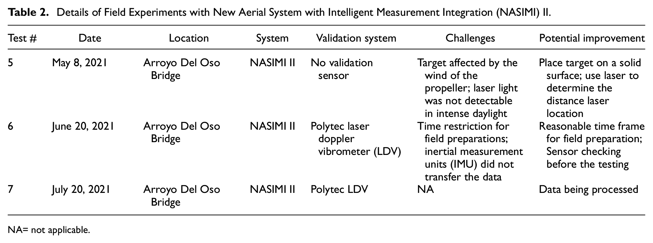
NA= not applicable.
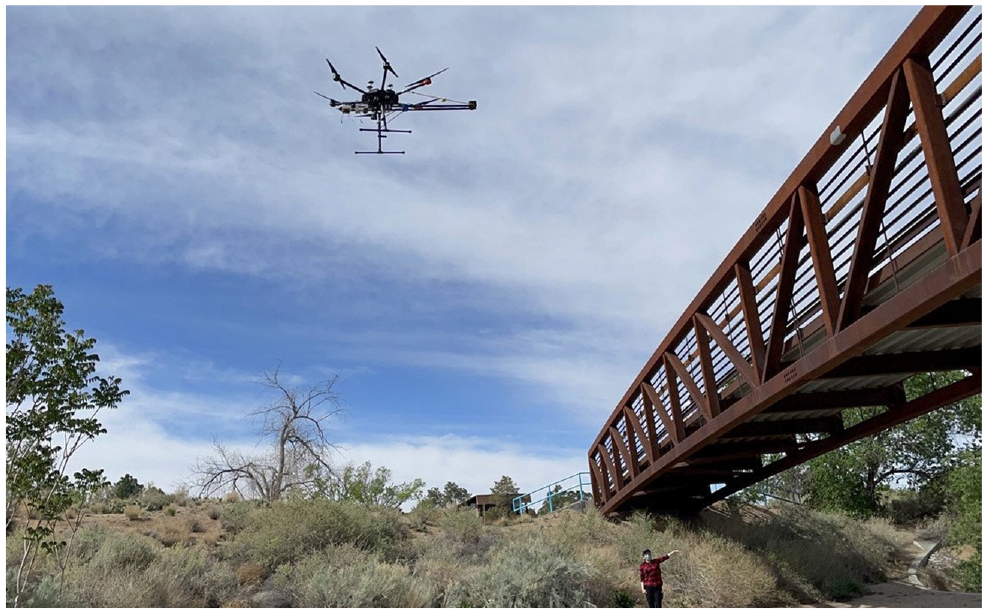
Unmanned aerial vehicle experiment with new aerial system with intelligent measurement integration (NASIMI) II, test #5.
Software Considerations
Sensor Fusion
Sensor fusion is used to improve the estimations and signals from sensors and integrate their capabilities. There are multiple methods to this end. Some researchers have used sensor fusion techniques to improve their camera estimation by integrating the camera with an additional sensor (
21
). There are several filters used for fusing sensor readings such as complimentary filter, Kalman filter, and extended Kalman filter, among others. Recently, researchers have fused the camera estimation with an accelerometer to improve the camera estimations (
22
). In this study, a Kalman filter was used to fuse the camera and IMU signals and improve camera estimation. Kalman filter intakes the priori and calculates the posteriori through a measurement update and time update procedure and in an iterative process. Considering


where
A = the state translation matrix
B = control input matrix
C = measurement matrix
X k−1 = previous state vector
ω k−1 = control noise vectors
ϑ k−1 = process noise vectors
Kalman filter assumes that the noises are Gaussian.
Structure from Motion
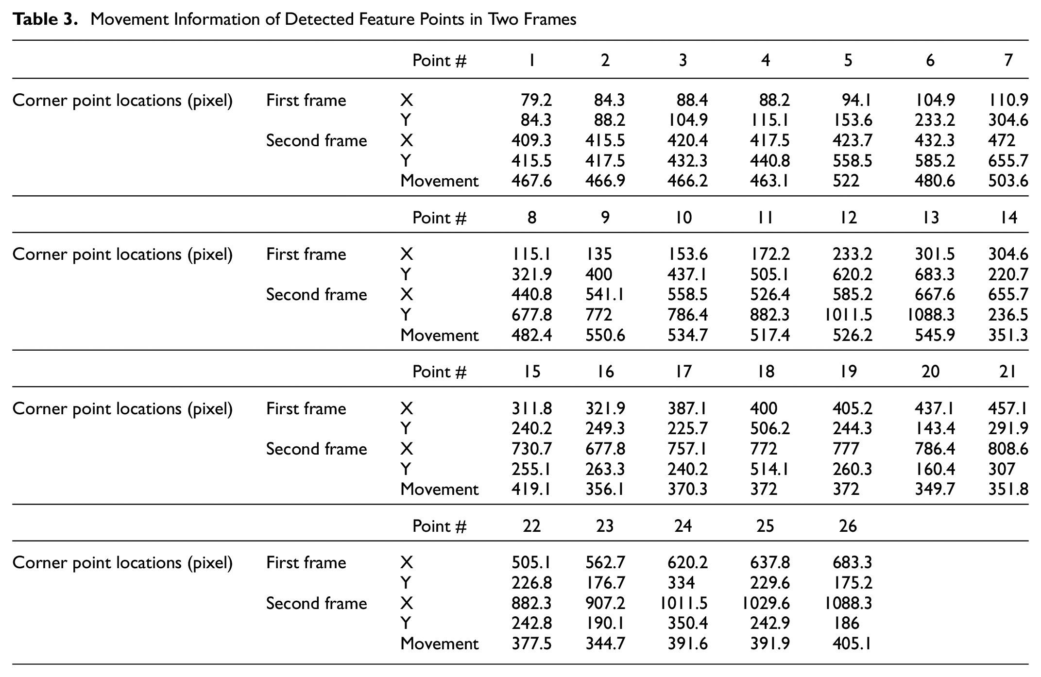
The system is designed to find the position of the UAV using a ground base target. It uses a target of a known size, in this case a checkerboard, to track the hovering of the UAV. While a textured target is ideal for the cases that film a textureless surface like asphalt, it can have downsides for some applications. In the third and the fifth field tests, the camera data experienced an average of one frame lost per second and the target was affected by the propeller’s wind, respectively. Additionally, if the bridge is built on a waterbody, it can be difficult to have a fixed target under the flying UAV. To address this concern, the researchers propose using an external camera instead of the camera attached to the UAV. A video captured from an external camera filming the UAV during the flight can give the hovering information of the UAV. Structure from motion (sfm) is an indirect camera position estimation method, where Figure 6 shows the flow chart of the proposed method. The team used some positive and negative instance images to train a code for detecting the UAV in each input image. Subsequently, the feature points were extracted and the UAV’s displacement tracked in two directions. Figure 7 shows the detected UAV in a bounding box and tracked feature points in two different frames of test number 4. As shown in Figure 7c, the algorithm detected and tracked 26 points on the UAV between the frames. The X, Y coordinates in pixels and the movement of each point between frames are listed in Table 3.
Movement Information of Detected Feature Points in Two Frames

Flow chart of the camera algorithm.

Video process results: (a) detected drone in the first frame, (b) detected drone in the second frame, and (c) tracked detected points between the frames.
Conclusion
UAVs are low-cost and promising tools for bridge inspections. In recent years, several researchers have used UAVs for the assessment of inaccessible locations in infrastructure and other civil systems. This paper aims to introduce a practical and implementable UAV system along with a methodology for using UAVs to obtain total dynamic transverse displacement. The researchers applied the comments from railroad experts and utilized experience from multiple field tests to upgrade their preliminary UAV system, NASIMI. This paper first discusses the NASIMI system and its achievements. Subsequently, it introduces the potential for improvement of NASIMI and the steps for creating NASIMI II. The new aerial system uses a similar concept but a new sensing system by adding an IMU. NASIMI II replaces the laser and its data logger with a higher range one, and modifies the algorithm by taking advantage of sensor fusion filters to enhance accuracy. Finally, the authors propose a new implementation of an sfm algorithm to eliminate the need for a ground base pattern and enable the system to be operable over waterbodies. NASIMI and NASIMI II are the first examples of UAV–laser systems for obtaining total dynamic transverse displacement. Promising achievements with these UAV systems show the potential of the proposed system for conducting non-contact inspection of inaccessible locations.
Footnotes
Acknowledgements
The authors acknowledge the support and feedback from the expert review panel of the research from the beginning: Dr Rafael Fierro, Martita Mullen, Dr David Mascarenas and RS-37 project manager Dr Velvet Fitzpatrick. The authors extend their thanks to SMIlab researchers Marlan Ball, Dominic Thompson, Jennifer Restrepo, Solomon Atcitty, James Woodal for their assistance in various experiments and the UAV pilots Dr Nicolas Cobo and Dr Matthew Fricke. The authors thank Mr Roger Ebner from the City of Albuquerque for the assistance in accessing the pedestrian bridge for testing in coordination with Parks and Recreation and the Albuquerque Police Department.
Author Contributions
The authors confirm contribution to the paper as follows: study conception and design: R. Nasimi, F. Moreu, M. Nasimi; data collection: R. Nasimi, F. Moreu, M. Nasimi; analysis and interpretation of results: R. Nasimi, M. Nasimi; draft manuscript preparation: R. Nasimi, F. Moreu, M. Nasimi, R. L. Wood. All authors reviewed the results and approved the final version of the manuscript.
Declaration of Conflicting Interests
The author(s) declared no potential conflicts of interest with respect to the research, authorship, and/or publication of this article.
Funding
The author(s) disclosed receipt of the following financial support for the research, authorship, and/or publication of this article: This work is funded by the National Academy of Science Transportation Research Board (TRB), Rail Safety IDEA Project 37: Measuring Behavior of Railroad Bridges under Revenue Traffic Using Lasers and Unmanned Aerial Vehicles (UAVs) for Safer Operations: Implementation, Project No. 163418-0399, and New Mexico Consortium: Cyber-security of Critical Infrastructure Using Sensors and New Technologies, project number: 027433.
Data Accessibility Statement
The data of this study are available from the authors on reasonable request.