



Abstract
New top-mounted sockets for use with the weak-post, Midwest Guardrail System (MGS) on low-fill culverts were developed and evaluated. The system was adapted from the MGS bridge railing for attachment to the top slab of a concrete box culvert. Three design concepts were developed and evaluated through dynamic component testing. Both lateral and longitudinal impact tests were conducted on the design concepts while mounted to simulated concrete culverts. Two concepts, a cylindrical concrete foundation and a steel tube socket assembly, proved strong enough to withstand the impact loads transferred from the posts without sustaining significant damage or displacements. However, the third concept, a concrete slab, fractured and allowed the sockets to rotate back without developing the post bending strength. Thus, only the cylindrical concrete foundation and the steel tube socket assembly in combination with the weak-post, MGS were determined to be crashworthy according to the Manual for Assessing Safety Hardware (MASH) Test Level 3 safety criteria. The new top-mounted, socketed, weak-post, W-beam MGS for low-fill culverts has multiple advantages over other guardrail treatments for culverts. The guardrail system has an unrestricted system length and does not require a transition when attached to the MGS. The top-mounted system can be placed parallel to the roadway with a constant lateral offset regardless of the position and orientation of the culvert headwall. Additionally, the attachment configurations were designed utilizing epoxy anchors, enabling the system to be installed on new or existing culverts. Finally, the sockets remain undamaged during impact events, allowing for quick repairs.
Concrete box culverts are routinely installed under roadways to allow water drainage without affecting the motoring public. Unfortunately, these box culverts can also represent a hazard on the roadside when they do not extend outside of the clear zone and often require safety treatments in the form of roadside barriers. The most common safety barriers utilized to shield these areas are W-beam guardrail systems. However, low-fill culverts with less than 40 in. of soil fill prevent the proper installation of standard guardrail posts because of a lack of available embedment depth. Numerous box culverts across the country utilize low-fill soil above the top slab, typically in the range of 1 to 3 ft. Previous crash testing has shown that W-beam installations with shallow post embedment do not perform adequately and are prone to vehicle override ( 1 ). Therefore, low-fill culverts require specialized guardrail systems to safely treat the hazard.
Currently, three different types of guardrail systems are being used to treat cross-drainage box culverts: (1) long-span guardrail systems; (2) guardrail systems anchored to the top slab of the culvert; and (3) guardrail systems mounted to the outer face of the culvert headwall (e.g., weak-post, guardrail system bridge railing).
Long-Span Guardrail Systems
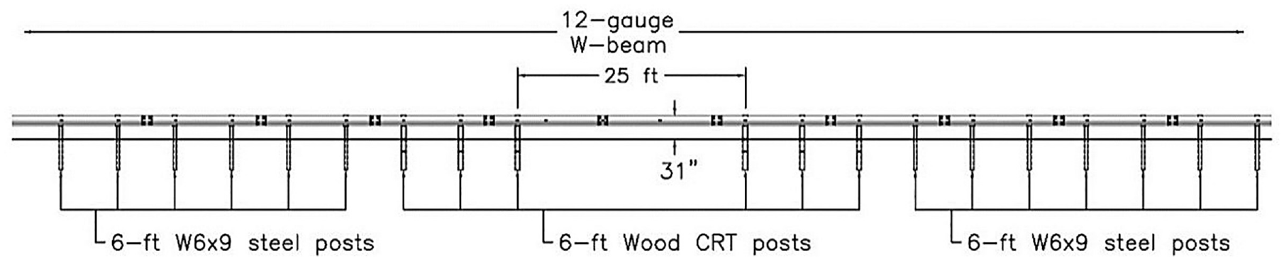
Long-span guardrail systems contain unsupported lengths of W-beam rail that span over the top of culverts. These barrier systems do not require attachment to the culvert, thus allowing the culvert and the barrier system to operate independently. One long-span system consists of a single layer of 12-gauge, 31 in.-tall W-beam guardrail centered over a 25 ft unsupported span length, as shown in Figure 1 ( 2 , 3 ). This system satisfied the safety criteria of AASHTO’s Manual for Assessing Safety Hardware (MASH) Test Level 3 (TL-3) ( 4 ). Long-span systems do not require additional components for attachment to the culvert but do require three wood controlled release terminal (CRT) posts on each side of the elongated span to prevent vehicle snag and pocketing. Unfortunately, long-span systems are limited to a maximum unsupported span length of 25 ft.
Top-Mounted, Culvert Guardrail Systems
For low-fill culverts of widths exceeding the maximum unsupported length of long-span systems, a few W-beam guardrail designs are available for direct attachment to the culvert’s top slab. One such guardrail system utilized W6x9 steel posts, spaced 37½ in. on center, with 27¾ in. top rail height, a deformable ½ in.-thick steel base plate, and four 1 in.-diameter threaded anchors ( 5 – 7 ), as shown in Figure 2a. The post assembly was anchored to the culvert slab using four 1 in.-diameter through-bolts. Finally, the back side of the posts was offset 18 in. from the culvert headwall to prevent interaction between the posts and the rigid headwall as the system deflects during an impact event. This system was successfully full-scale crash tested according to the TL-3 safety performance guidelines found in NCHRP Report 350 ( 8 ). Recently, the system was also successfully tested to MASH standards with a top rail height of 31 in. and the post offset 12 in. from the headwall, as shown in Figure 2b ( 9 ).
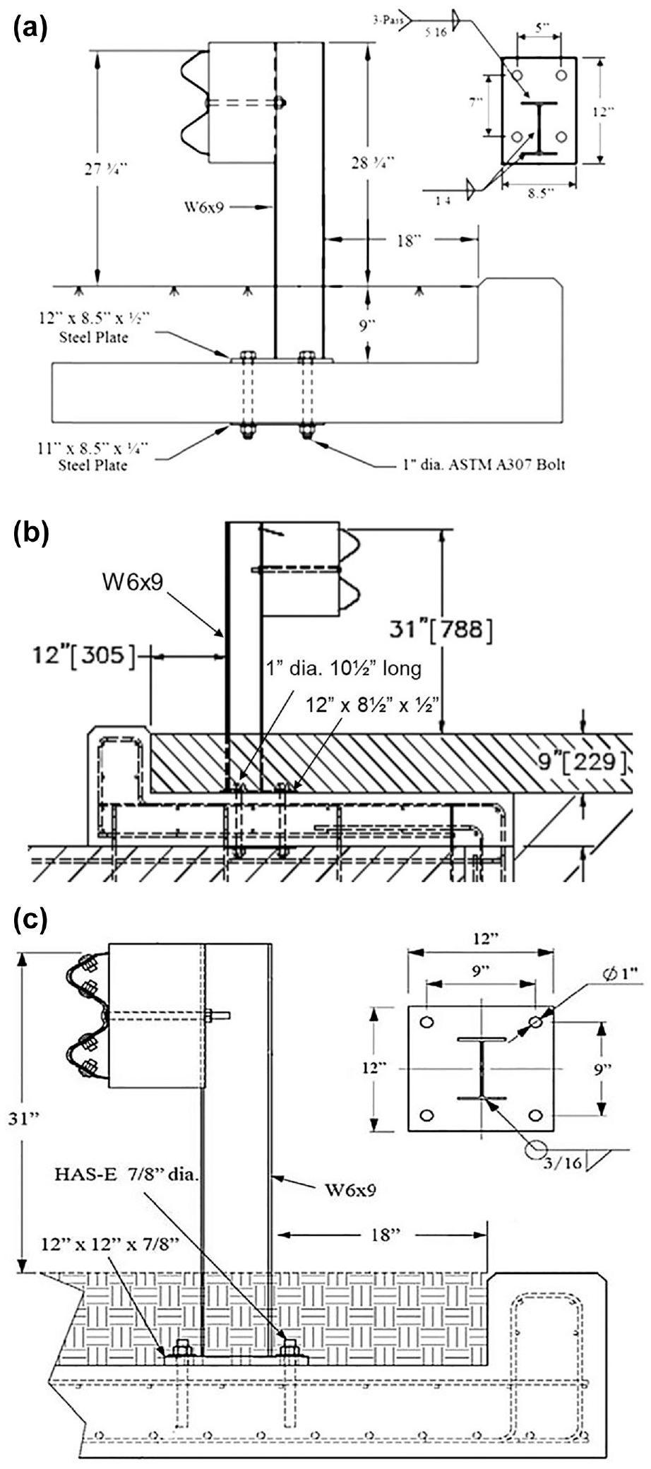
A similar system was developed to satisfy MASH criteria using a rigid baseplate and standard 75 in. post spacing. The system utilized W6×9 steel posts, a thicker, ⅞ in.-thick base plate, and a 31 in. top rail height ( 10 ), as shown in Figure 2c. All top-mounted guardrail systems described here were designed for use with a minimum fill depth of 9 in. on the culverts as well as 12 in. or 18 in. lateral offsets between the back of the post and the inside of the culvert headwall. This offset is necessary to allow the post to rotate back freely without contacting the headwall. These lateral offsets, coupled with the footprint of the system itself, result in the loss of 5 ft or more of traversable roadway width. Additionally, when these systems are impacted, the fill soil must be removed around damaged top-mounted posts to gain access to the anchor bolts and replace damaged posts. This soil removal and replacement after the new post is installed adds to repair time and labor costs.
Side-Mounted, Weak-Post, Culvert Guardrail Systems
The weak-post, MGS bridge rail incorporates 31 in.-tall W-beam guardrail, S3×5.7 post spaced at 37.5 in. on-center and attaches to the side of concrete bridge decks (similar to headwalls of concrete box culverts) ( 11 , 12 ). The posts are inserted into HSS4×4×⅜ steel sockets placed along the outside edge of the bridge deck. Each socket is attached to the bridge deck with a 1 in. diameter ASTM A307 vertical through-bolt and a bottom steel angle, as shown in Figure 3. The placement of the posts and sockets off the edge of the bridge deck, coupled with the use of W-beam backup plates instead of blockouts, allows for minimal intrusion into the roadway and maximizes the traversable width.

Although the weak-post, MGS bridge rail was originally designed for use on bridge decks, it had a few characteristics that make it attractive for use on concrete culverts. First, the use of weak S3×5.7 posts limits the load transferred to the bridge deck and reduces the risk of deck damage. Second, the system was designed to absorb energy through post bending while the socket and attachment hardware remain undamaged. Thus, repairs to an impacted system are relatively quick and easy and require only the removal of the damaged posts and insertion of new posts. Third, weak-post systems do not include blockouts, so they have minimal footprints that help maximize the traversable width of the roadway. Finally, the use of weak S3×5.7 posts and reduced post spacing resulted in the lateral stiffness and dynamic deflection of the weak-post, MGS bridge rail being very similar to standard strong-post MGS. Therefore, the two systems can be directly attached to each other without the need for a guardrail transition.
Recognizing the potential benefits of adapting the weak-post, MGS bridge rail for other uses, a side-mounted socket system for weak-post MGS was developed for attachment to the outside face of culvert headwalls ( 13 ). Similar to the original MGS bridge rail, the system utilized a top rail height of 31 in. supported by S3×5.7 posts, spaced 37½ in. on center and positioned within HSS4×4×⅜ steel socket tubes However, the socket attachment hardware had to be redesigned for attachment to the outside face of culvert headwalls. Multiple attachment configurations, including a top-mounted, single-anchor configuration, which was similar to the original bridge rail socket anchorage design, and a side-mounted configuration, as shown in Figure 4, were developed and evaluated through dynamic component testing. All the tested socket attachment configurations prevented damage to the socket assembly and culvert headwall. More details on the socket assembly and attachment hardware can be found elsewhere ( 13 ).

Top- and side-mounted configurations for guardrail on culvert headwalls ( 13 ).
Unfortunately, at many installation sites the culvert or roadway geometry is not compatible with the aforementioned side-mounted system. For example, the culvert headwall may be farther from the roadway than the adjacent guardrail system. Additionally, there may be a fill slope between the edge of the roadway and the culvert headwall, and the side-mounted guardrail system was only designed for level terrain applications. Therefore, a top-mounted socket to attach the weak-post, W-beam guardrail system to the top slab of low-fill box culverts was desired.
Design Criteria
The objective of this project was to develop a top-mounted, socketed, weak-post guardrail system for low-fill culverts that satisfied MASH TL-3 safety criteria. The new system was to be adapted from the weak-post, MGS bridge rail. Thus, the system would utilize 31 in.-tall W-beam rail, S3×5.7 posts spaced at 37.5 in. on-center, and HSS 4×4×⅜ steel socket tubes. Specifically, it was desired to utilize the same post assembly as the weak-post MGS bridge rail and the side-mounted guardrail system for culverts. Thus, 44 in.-long S3×5.7 posts with ¼ in.-thick standoff plates at the base of the post, as shown in Figure 5, were incorporated into the design. Similar to previous systems, the socket was required to extend 2 in. above the ground line to encompass the upper standoff plates on the post and to ensure the posts would bend at the same location during impacts. Thus, the new top-mounted guardrail system would provide the same stiffness and performance as the previously developed systems.

Post assembly for socketed, weak-post guardrail systems.
The top-mounted sockets had to transfer the impact loads, which were limited to the plastic bending forces of the posts, to the top slab of the culvert without sustaining significant damage. Minor steel deformations or concrete cracking would be allowed as long as the socket assembly could be reused without requiring repairs. Additionally, socket displacements during impacts had to be limited to ensure damaged posts could be replaced without resetting of the socket. Previous studies on socketed foundations for cable barrier posts have specified a 1 in. maximum displacement of sockets at the ground line to ensure reusability ( 14 , 15 ). The same restriction was adopted for the top-mounted sockets on culverts developed here. The culvert and all attachment hardware were to remain undamaged. The top-mounted sockets were desired for use on both new and existing culvert structures. Subsequently, the sockets had to be attached to the culvert utilizing either epoxy anchors or through-bolts.
As culvert depths vary by site location, the top-mounted sockets needed to be compatible for a variety of soil fill depths. It was desired for the top-mounted socketed design to accommodate soil fill between 1 ft and 3 ft. However, the post assembly (i.e., the location of the standoff plates near the bottom of the post) required the post to extend 12 in. below the ground line. It was assumed that any socket design would require a base plate, which needs the socket assembly to extend beyond 12 in. Thus, the minimum soil fill height was increased slightly to 12.5 in.
Design Details
Three design concepts to support the top-mounted, steel sockets were developed and evaluated: (1) a cylindrical concrete foundation; (2) an all-steel socket assembly; and (3) a concrete slab.
Design Concept 1: Cylindrical Concrete Foundation
Midwest Roadside Safety Facility (MwRSF) had previously developed a series of socketed foundations to support S3×5.7 posts as part of the development of a new non-proprietary cable barrier system ( 14 ). These reinforced concrete foundations were cylindrical in shape and incorporated a 4 in. × 4 in. steel tube socket, which was embedded down the center of the foundation, as shown in Figure 6. These foundations were reinforced with both vertical rebar and transverse hoops and showed only minor damage and/or movement when subjected to impact loading. Thus, these concrete foundations were selected as a potential design for use on top of culvert slabs.

Cylindrical concrete foundations for S3×5.7 cable barrier posts ( 14 ).
A few design changes were necessary to adapt the cylindrical concrete foundations for use in the top-mounted culvert guardrail system. First, the steel socket had to be extended 2 in. above the top of the concrete foundation to accommodate the post assembly and maintain the same post hinge point as the previous systems. Second, the vertical rebar was extended out of the bottom of the foundation so that it could be anchored to the top slab of a culvert.
The cylindrical concrete foundations measured 12 in. in diameter and were reinforced by a combination of vertical rebar and transverse hoops, both of which were #4 rebar. The concrete was specified to have a minimum unconfined compressive strength of 3,500 pounds per square inch (psi) and all rebar were ASTM A615 grade 60. The vertical rebar extended 7 in. from the bottom of the concrete foundation and were epoxied into the top slab of the culvert. A 14 in.-long HSS 4×4×⅜ steel tube socket was embedded 12 in. down the center of each foundation and extended 2 in. from the top surface. Although the socket depth and cylinder diameter would remain constant, the height of the cylindrical foundation would vary to match the soil fill depth of the culvert. Thus, the foundation’s top surface was flush with the level soil fill, while the top of the socket extended 2 in. above the ground line, as shown in Figure 7.

Cylindrical concrete foundation design for 12.5 in. and 36 in. soil fill depths.
Design Concept 2: Steel Tube Socket Assembly
The second design concept was a steel socket assembly consisting of an HSS 4×4×⅜ steel tube socket, a base plate, and any additional reinforcements necessary to prevent deformations during loading. Similar to the cylindrical concrete foundations, the height of the steel tube sockets would be dependent on the soil fill depth on the culvert. The steel tube was placed in the center of a ½ in.-thick base plate, which was anchored to the top slab of the culvert with four ¾ in.-diameter threaded rods. These anchors could be either epoxied into the culvert top slab or extended through the slab and fastened with nuts on the underside of the slab. The height of the steel tube would vary based on the soil fill depth to ensure that the top of the socket extended 2 in. above the ground line, as shown in Figure 8.

Steel socket assembly design concept for 1 ft and 3 ft soil fill depths.
Preliminary calculations showed that the HSS 4×4×⅜ tubes were not strong enough to support the impact loads transferred from the guardrail posts, especially for larger soil fill depths, without sustaining plastic deformations. Thus, 6 in.-wide by ¼ in.-thick reinforcing plates were welded to the front and back faces of the socket tube. The reinforcing plates extended from the base plate to 8 in. from the top of the socket, as shown in Figure 8. These plates not only doubled the bending strength of the socket assembly, but also increased the soil resistance to displacement by increasing the width of the socket assembly by 50 percent. The steel plates were fabricated from ASTM A572 Grade 50 steel, whereas the threaded rods were ASTM A449. A 5/8 in.-diameter bolt was placed through the socket to support the post vertically and ensure it extended exactly 12 in. below the ground line, or 14 in. into the socket.
Design Concept 3: Concrete Slab
The final design concept selected for evaluation was a steel socket embedded within a concrete slab. MwRSF had previously developed weak-post MGS systems for use in either asphalt or concrete mow strips ( 16 ). In this previous mow-strip configuration, which did not utilize sockets, S3×5.7 posts were inserted into 4 in.-square leave outs located down the middle of a 4 in.-thick concrete mow strip and driven to an embedment depth of 40 in., or 36 in. below the mow strip. One advantage of utilizing a similar design would be that neither the slab nor the guardrail posts needed to be anchored to the culvert. Thus, the culvert and the barrier system act independently of each other. Additionally, the same slab and socket geometry could be utilized for all culvert installations regardless of the soil fill depth.
For the new socketed guardrail system, the previous weak-post guardrail in mow-strip configuration was modified to include HSS 4×4×⅜ steel tube sockets. The sockets were placed 24 in. from the back of a slab within a 36 in.-wide by 4 in.-thick unreinforced concrete slab, as shown in Figure 9. The tops of the sockets extended 2 in. above the top of the slab. The concrete had a compressive strength of 4,000 psi, and the socket was fabricated from ASTM A500 Grade B steel.

Concrete slab design concept.
Dynamic Component Testing
Evaluation Criteria and Testing Conditions
New highway barriers are typically evaluated through full-scale crash testing in accordance with MASH 2016 safety performance criteria to be deemed crashworthy. However, the original weak-post, MGS bridge rail ( 11 , 12 ) had already been successfully crash tested to MASH TL-3 criteria, and this study focused only on adapting the original system for use as a top-mounted barrier on low-fill box culverts. The W-beam rail, rail-to-post attachment hardware, mounting height, post assembly, and socket tube remained unchanged from the original bridge rail. The only new components in these concepts were the attachment hardware utilized to mount the socket to the top slab of the culvert. Recall, the socket assemblies and attachment hardware were designed to withstand impact loads and remain undamaged while the post and rail components deform and absorb energy during impact events. Thus, if these new attachment components were shown to withstand extreme post loading conditions without damage to the socket assembly or the culvert slab, the new weak-post guardrail attached to concrete box culvert systems would perform similarly to the original weak-post, MGS bridge rail. Thus, full-scale crash testing was deemed unnecessary, and the evaluation of the new design concepts was limited to dynamic component testing. A similar design approach was successfully utilized to adapt the weak-post, MGS bridge rail for attachment to the face of culvert headwalls ( 13 ).
Each design concept was subjected to dynamic impacts with a bogie vehicle striking the posts inserted into the socketed attachment configurations. Evaluations were based on displacement of the socket and damage to the socket, attachment hardware, and the culvert as the post deflected during the impact event. The sockets were required to displace less than 1 in., as measured at the ground line. Damage to the test installations had to be negligible to the point that repairs to the socket assemblies would not be necessary. Thus, only posts and guardrail segments would need to be replaced after an impact event.
Two critical impact conditions were identified for the evaluation of the socket attachment designs. The first involved a lateral impact (90-degree impact angle) on the post at a height of 24⅞ in. The impact height corresponds to the height to the center of the W-beam rail, and the impact angle results in strong-axis bending of the post, or the maximum lateral loading to a single post and socket location. The second critical test condition involved a longitudinal impact (0-degree impact angle) where a post was subjected to weak-axis bending. The longitudinal impacts were conducted with a load height of 12 in. to simulate a small car bumper impacting posts during a redirection. This second impact was deemed critical, because it induces high shear loads into the socket which may result in socket displacements and/or rotations in the longitudinal direction. If a socket can withstand both critical loading conditions without significant deformations and damage, it would be able to provide the anchorage support needed for the guardrail system to perform as intended.
Test Installation Configurations
A version of this socketed, weak-post MGS system was previously adapted for use on the outside face of culvert headwalls ( 13 ). As part of the previous project, a survey of existing culvert standards was conducted to identify a critical culvert configuration for use in testing. The same critical culvert configuration was selected for use in the evaluation of the top-mounted sockets. The culvert had a top slab thickness of 9 in. and a 12 in.-wide headwall that extended 9 in. above the top slab. The culvert top slab was reinforced with top and bottom mats of steel consisting of #4 rebar spaced at 12 in. longitudinally and 18 in. laterally. The concrete had a minimum compressive strength of 4,000 psi.
The fill depth and grading of the soil on the culvert was also critical to the evaluation of the top-mounted socket attachments. In general, the maximum soil fill depth would be critical as it would induce the highest bending loads to the socket assembly. Thus, nearly all dynamic component tests were conducted on a simulated culvert with a 3 ft soil fill depth. However, minimizing the soil fill depth would minimize the soil resistance against the socket assembly and may result in higher anchor loads. As the cylindrical concrete foundations only had one front anchor (in the tension area) as opposed to the two anchors on the front side of the steel socket assembly, the concrete foundation installed with minimum soil fill was also considered critical in the evaluation of the foundation anchorage. Therefore, two simulated culverts with soil fill depths of 12.5 in. and 36 in., respectively, were constructed at the MwRSF test site for use in the testing of the socketed attachments.
Further, soil fill on top of culverts and beyond the roadway shoulder is often sloped. Sloped terrain can significantly affect the performance of a guardrail system by reducing the soil fill behind the post, or in this case, the socket. Thus, the soil fill on both culverts was installed with a 2H:1V slope that began at the culvert headwall and extended up to the desired soil fill depth before leveling off. The original weak-post, MGS bridge rail and all its adaptations have been developed and evaluated solely on level terrain in front of the barrier. Placement of the guardrail system on sloped terrain could significantly affect its performance. Thus, the top-mounted sockets were positioned on the culvert with the back of the socket assembly adjacent to the slope break point of the 2H:1V slope during the dynamic component testing and evaluation. Photographs of the test installations are shown in Figures 10 to 12.

Test installation photographs for cylindrical concrete foundations.

Test installation photographs for steel tube socket assemblies.
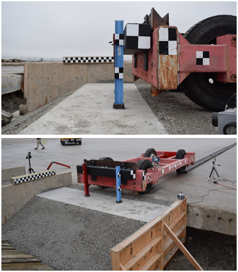
Test installation photographs for concrete slab configuration.
During the previous evaluation and testing of weak posts in pavement mow strips ( 16 ), different failure patterns were observed depending on the number of posts impacted. During single-post component tests, only localized damage was observed directly behind the post. However, if two posts were impacted simultaneously, the stress distributions from adjacent posts would overlap and cause the mow strip to fail and split down the middle. This behavior was observed in dual post component testing as well as in the full-scale crash test ( 16 ). Therefore, the lateral component test on the concrete slab design concept was conducted as a dual post impact with the posts spaced at 37.5 in. on center, as shown in Figure 12.
Finally, placement of a fill slope adjacent to the socket assemblies would adversely affect the path and stability of the bogie vehicle during longitudinal impacts. Instead of constructing separate culverts to conduct the longitudinal tests, the test articles installed for longitudinal impacts were rotated 90 degrees. Thus, the bogie tow path, which ran laterally with respect to the culvert, could remain on level terrain before impact, but the impact loads would be through the longitudinal, or weak axis, of the post and socket assembly. This scenario resulted in a reduced, and unrealistic, amount of soil fill behind the longitudinally impacted test articles. However, if damage and displacement was limited under these conditions, the socket assembly would certainly also perform acceptably in more favorable and realistic conditions with the additional soil behind the test article.
Dynamic Component Testing Matrix
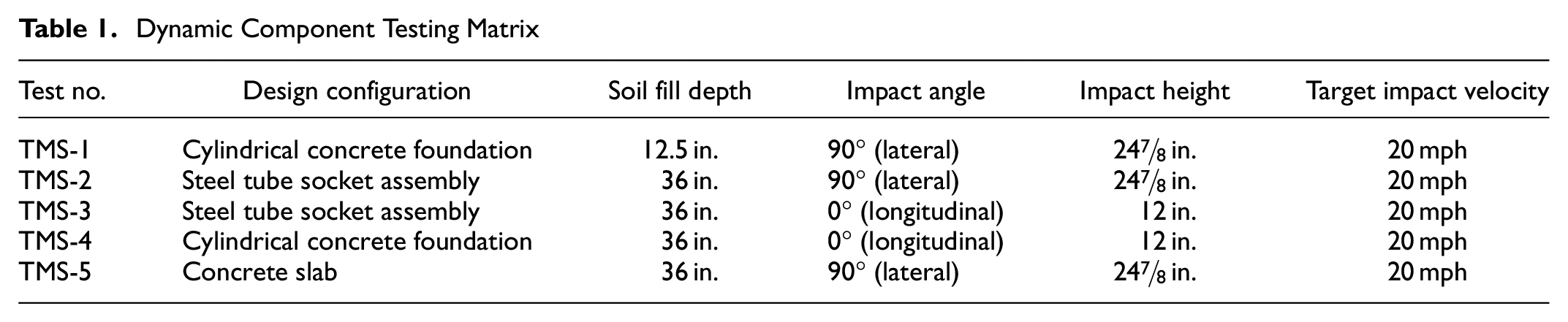
A total of five dynamic component tests were conducted on critical configurations of the various design configurations. Each design concept was impacted laterally (causing strong-axis bending) with an impact height of 24⅞ in. Pending successful lateral tests, the design concepts were then subjected to a longitudinal impact (causing weak-axis bending) with an impact height of 12 in. The target impact velocity was 20 mph for all five tests. Test nos. TMS-1 and TMS-4 were conducted on cylindrical concrete foundations with a 12.5 in. and 36 in. soil fill depth, respectively. Test nos. TMS-2 and TMS-3 were conducted on steel tube socket assemblies with a 36 in. soil fill depth, and test TMS-5 was conducted on a dual post installation within a 4 in.-thick concrete slab measuring 9 ft long by 3 ft wide. The testing matrix is shown in Table 1.
Dynamic Component Testing Matrix
Dynamic Bogie Testing Results
Testing of both the cylindrical concrete foundations (test nos. TMS-1 and TMS-4) and the steel tube socket assemblies (test nos. TMS-2 and TMS-3) produced favorable results. The S3×5.7 posts were bent over, but the sockets received only minor damage and minimal permanent set displacements. No damage was observed to the simulated culvert or attachment hardware.
Testing of the cylindrical concrete foundations consisted of a lateral impact with the minimal soil fill depth of 12.5 in. (test no. TMS-1) and a longitudinal impact with the maximum soil fill depth of 36 in. (test no. TMS-4) to bracket the behavior of the concrete foundations. These tests resulted in only minor cracking on the top surface of the foundations and negligible permanent set displacements, as shown in Figure 13. Thus, these socketed concrete foundations remained essentially rigid and would not require repairs after an impact event.

Post-test damage to cylindrical concrete foundations from: (a) lateral and (b) longitudinal impacts.
Testing of the steel tube socket assemblies (test nos. TMS-2 and TMS-3) was conducted with the maximum soil fill depth of 36 in. to maximize the potential for bending and displacement of the sockets. Both the lateral and longitudinal tests resulted in minor deformations to the socket assemblies and displacements of 0.52 in. and 0.23 in., respectively, to the top of the socket, as shown in Figure 14. These displacements were well within the 1 in. limits. Thus, repairs to the steel tube socket assemblies would not be necessary following an impact event. Note, lower socket displacements than those measured here would be expected for installations placed on level terrain or adjacent to shallower fill slopes because of the increased soil fill behind the socket.

Post-test damage to steel tube socket assemblies from: (a) lateral and (b) longitudinal impacts.
Testing of the concrete slab (test no. TMS-5) was conducted such that the bogie vehicle impacted two posts simultaneously to evaluate the potential for impact loads between adjacent posts to cause shear failure within the concrete slab. The test resulted in catastrophic slab failure that began with concrete shear cracking that ran between the sockets and extended backward at a 45-degree angle. The 4 in.-thick slab did not have enough strength to support the S3×5.7 posts. The posts and sockets sustained minimal deformations as they rotated through the fractured concrete slab, as shown in Figure 15. Therefore, a 4 in.-thick concrete slab did not demonstrate enough strength to support the weak-post MGS sockets and was not deemed crashworthy. Further details can be found in the test report ( 17 ).
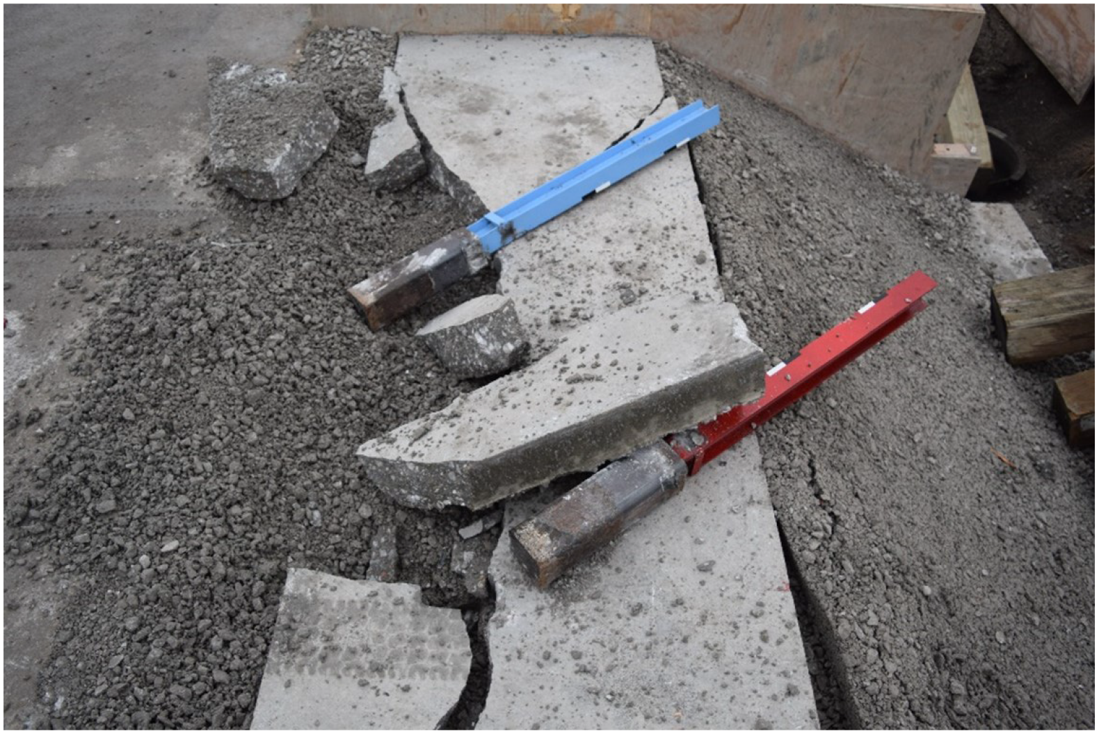
Post-test damage to 4 in.-thick concrete slab.
After the tests were conducted, the soil fill was removed to inspect damage below the ground line. No damage was observed to the simulated culverts or socket attachment hardware during any of the tests. A summary of the dynamic component testing is shown in Table 2. The average impact forces over the 10 in. and 20 in. bogie displacement are also shown in Table 2.
Dynamic Component Testing Summary Results

Note: Ave. = average; Max. = maximum; Dyn. = Dynamic; Perm. = Permanent; na = not applicable.
The impact forces recorded between the concrete foundations and the steel tube socket assemblies were very similar in both impact orientations, as they should be as post bending was the failure mechanism in all four of these tests. The concrete foundation tests did show a slight increase in peak forces, which is likely because they did not displace as far as the steel tube socket assemblies. On a per post basis, the peak force and the forces early in test no. TMS-5 were similar in magnitude to the forces observed in the other two lateral tests. However, once the concrete slab fractured apart at a post displacement of about 5 in., the forces dropped rapidly to near zero for the duration of the impact event.
Conclusions and Recommendations
New top-mounted, sockets for weak-post MGS were developed for attachment to concrete box culverts and component tested to determine their ability to support the guardrail system posts. Thus, the system would utilize 31 in.-tall W-beam rail, S3×5.7 posts spaced at 37.5 in. on center, and HSS 4×4×⅜ steel socket tubes. The new top-mounted design utilizes the same post assembly as the original weak-post MGS design, which avoids confusion and allows agencies to stock only a single post type for both the weak-post MGS bridge rail and the new culvert rail design. The socket mount assembly and attachment hardware, on the other hand, had to be modified to accommodate mounting to the top slab of concrete box culverts.
Three different socket configurations, including cylindrical concrete foundation, steel tube socket assembly, and concrete slab, were designed and component tested. Both the cylindrical concrete foundations and the steel tube socket assemblies remained relatively rigid during the impact tests as they remained largely undamaged and limited permanent set displacements to well within the desired 1 in. limit. Additionally, the simulated culvert and the attachment hardware remained undamaged. Thus, both the cylindrical concrete foundations and the steel tube socket assemblies will provide adequate strength to support the S3×5.7 posts.
However, testing of the sockets encased within a 4 in.-thick unreinforced concrete slab resulted in complete fracture of the slab. The sockets rotated through the fractured concrete slab before the formation of plastic bending hinges within the posts. Therefore, the 4 in.-thick concrete slab was not strong enough to support the S3×5.7 posts and is not recommended for use.
MASH 2016 requires two full-scale crash tests for the evaluation of longitudinal barrier systems to TL-3. However, full-scale crash testing was not deemed necessary to evaluate the performance of the top-mounted, socketed, weak-post MGS attached to culvert slabs. The top-mounted system was adapted from the weak-post MGS bridge rail, which was designed to have the sockets remain essentially rigid while the posts and W-beam rail deform and absorb energy. During the successful full-scale crash testing of the original weak-post MGS bridge rail to MASH test designation nos. 3-10 and 3-11, the side-mounted sockets remained free from plastic deformations and significant displacements throughout the impact event ( 11 – 12 ). Thus, all system deflections and energy absorbed by the system were solely attributed to post bending and rail deformations. The top-mounted, socketed, weak-post MGS configurations for attachment to concrete culverts incorporate the same W-beam rail, rail-to-post attachment hardware, mounting height, post assembly, and socket tube as the MGS bridge rail. Dynamic component testing showed that the new top-mount socket assemblies provide sufficient support to achieve full bending strength of the S3×5.7 posts with no measurable deformation. Thus, the two top-mounted, socketed, weak-post MGS configurations will perform similarly to the original weak-post MGS bridge rail and should be considered MASH TL-3 crashworthy.
With the development and successful testing of both the socketed concrete foundations and the steel tube socket assemblies, roadside designers have two options for installing a top-mounted, socketed, weak-post guardrail system on concrete box culverts. Either of these two socketed systems may be utilized at sites where the culvert headwall is not in-line with the adjacent guardrail, and it would be difficult to use the previously developed weak-post system attached to culvert headwalls ( 13 ). Additionally, these new top-mounted, weak-post guardrail systems are unrestricted in relation to system length, so they may be utilized to span over culverts that are too wide for long-span guardrail systems ( 2 , 3 ), which are currently limited to 25 ft unsupported span lengths. Finally, these socket assemblies and the culvert itself remained undamaged during the critical impact tests. Thus, repair to a damaged system would consist of simply removing damaged rail segments and posts, dropping replacement posts into the undamaged sockets, and bolting on new rail segments. This capability will significantly reduce repair time and costs compared with top-mounted strong-post systems (5–7, 9, 10), which require the removal of the soil fill to remove damaged posts and attach replacement posts to the culvert.
Implementation Guidance
The top-mounted sockets were designed to be compatible with soil fill depths between 12.5 in. and 36 in. Thus, the vertical dimensions of the top-mounted sockets can vary with the soil fill depth of each particular site. Both socket designs are to remain unchanged within the top 14 in. of the socket, which includes the 2 in. socket extension above the ground line. Changes should only occur to the foundations/socket assemblies below the bottom of the weak-post when it is inserted into the socket. Specifically, only the length of the vertical bars and the number of transverse hoops will vary with the height of the cylindrical concrete foundations. Note, the top of the concrete foundation should always be even with the ground line. For the steel tube socket assemblies, only the length of the HSS square tube and the ¼ in.-thick reinforcing plates located on the front and back faces of the tube will change. The reinforcing plates should always extend from the baseplate to 6 in. below the ground line, and the bolt supporting the post should remain 145/16 in. from the top of the socket.
The original weak-post MGS bridge rail was developed and evaluated in combination with 6 in.-wide W-beam backup plates located behind the rail at every post location. However, multiple full-scale crash tests conducted on similar weak-post guardrail systems ( 16 , 18 ) following the development of the weak-post MGS bridge rail have resulted in rail tearing as a result of contact between the W-beam rail and the posts. As such, it is recommended to utilize 12 in.-wide backup plates in all weak-post MGS systems, including the top-mounted system developed here.
To date, all the socketed, weak-post MGS variations have been evaluated with level terrain in front of the barrier. The introduction of an approach slope may negatively affect the performance of these systems in relation to vehicle capture and stability. Thus, it is recommended that approach slopes of 10H:1V or flatter be placed in front of the top-mounted, socketed, weak-post MGS on culverts. The top-mounted sockets evaluated here were tested with their back edges adjacent to a 2H:1V slope break point. Steeper soil slopes behind the system would reduce the soil stiffness behind the socket and may lead to excessive deformations. Thus, soil slopes behind the system should be limited to 2H:1V or flatter. If the use of steeper slopes is desired, the slope break point should be located a minimum of 2 ft laterally behind the sockets.
The original weak-post MGS bridge rail was full-scale crash tested while mounted to the side of a simulated bridge deck (i.e., it was tested without any ground to support the vehicles as they were being redirected). Additional surface behind the weak-post MGS should not affect the performance of the guardrail system. As such, there are no restrictions on the placement of the top-mounted sockets relative to the culverts, including directly adjacent to the headwall, as long as the socket assembly or foundation is properly anchored to the top slab. However, if the sockets are to be placed adjacent to the headwall, the headwall should not extend more than 2 in. above the ground. Headwalls extending further than 2 in. may act as vertical curbs and could pose a stability hazard. The weak-post MGS has not yet been evaluated in combination with curbed roadways.
This barrier system was designed as part of a family of non-proprietary, 31 in.-high, W-beam guardrail systems commonly referred to as the MGS. This new top-mounted, weak-post guardrail system attached to culverts was designed with a similar lateral stiffness and overall system performance to that observed for the original, strong-post MGS. Therefore, a stiffness transition between the new top-mounted culvert system and adjacent standard MGS installations is unnecessary. A 75 in. center-to-center spacing is recommended between the outer S3×5.7 weak-post on the culvert and the adjacent strong-post within the standard MGS installation next to the culvert. The adjacent MGS may be either blocked or non-blocked.
Footnotes
Author Contributions
The authors confirm contribution to the paper as follows: study conception and design: S.K. Rosenbaugh, R.K. Faller, and M. Asadollahi Pajouh; data collection: S.K. Rosenbaugh and R.K. Faller; analysis and interpretation of results: S.K. Rosenbaugh and R.K. Faller; draft manuscript preparation: M. Asadollahi Pajouh, S.K. Rosenbaugh, and R.K. Faller. All authors reviewed the results and approved the final version of the manuscript.
Declaration of Conflicting Interests
The author(s) declared no potential conflicts of interest with respect to the research, authorship, and/or publication of this article.
Funding
The author(s) disclosed receipt of the following financial support for the research, authorship, and/or publication of this article: The authors wish to acknowledge several sources that made a contribution to this project: (1) the Midwest Pooled Fund Program for sponsoring this project and (2) MwRSF personnel for constructing the system and conducting the crash tests.
