
Abstract
The Federal Highway Administration (FHWA) has recently developed the Portable Scour Testing Device (PSTD) to improve scour analysis around bridge piers in cohesive soils as part of the NextScour project. The PSTD is a compact field erosion testing device that, apart from a drill rig and larger water pump, has a lot of similarity with the In-situ Scour Testing Device (ISTD) in mechanism and data acquisition. The purpose of this paper is to provide recommendations on the suitability of using PSTD and ISTD at sites that have cohesive subsurface soils. An overview of the capabilities and limitations of the PSTD/ISTD in relation to hydraulic considerations, soil types, depth coverages, and erodibility potential is given. A multi-criteria assessment methodology to evaluate site suitability for conducting PSTD/ISTD is presented. The assessment methodology was utilized to detect suitable sites among 30 Illinois bridge sites using soil layer information, boring locations, groundwater level readings, in-situ testing results, geospatial analysis, site accessibility, and aerial photos.
Keywords
Bridge scour, or the soil removal from the riverbeds and riverbanks, is recognized as the leading cause of more than 60% of all bridge failures in the United States ( 1 ). In recent decades, numerous studies on bridge scour have mainly focused on using data-driven and risk-based approaches ( 2 ). Current hydraulic scour analysis practices assume that a riverbed soil is cohesionless, and this can lead to over predicting the estimated scour depths of cohesive soils. The Federal Highway Administration (FHWA) initiated the NextScour program to incorporate combined hydraulics and geotechnical factors in scour analyses through research, deployment, and technical guidance ( 2 ).
The In-situ Scour Testing Device (ISTD), developed by FHWA, is a patented scour device that is used to measure the erodibility of subsurface soils and provide data to engineers for predicting scour depth ( 3 ). The ISTD test involves eroding soils at a desired depth within a boring. This device consists of an erosion head, linear drive, enclosure, linear variable differential transformer sensors, flow meter, trash pump, generator, water tank, steel casing, pressure and suction hoses, and PVC piping that allows water flow to erode the soil in situ. The Portable Scour Testing Device (PSTD) is a simplified version of the ISTD, the most recent field erosion test device developed by FHWA. PSTD uses much of the same equipment as the ISTD but the process is simplified by conducting the test on an extracted core sample and at the surface, rather than within the bore hole and at depths. The PSTD approach eliminated the need to install additional casing, PVC water lines, and separated the erosion testing from the drilling effort. Conducting the test at the surface reduces the head loss through pipes and depths that occurs with the ISTD approach. Therefore, PSTD allows the use of a much smaller pump. Conducting the test at the surface also allows inspection of the sample before conducting the test. Also, a portion of the material in the Shelby tube can be taken to classify the material and get an indication of the strength with a pocket penetrometer or a Torvane.
The PSTD/ISTD generates a horizontal and radial flow at the bottom of the erosion head and in contact with the soil ( 3 ). The input data for PSTD/ISTD equipment are the erosion head position, which represents the soil position, and its corresponding flow rate. The erosion head position and flow rate, along with time, are continuously recorded as the erosion head erodes the soil and moves downward. The erosion rate under a specific tested flow rate is represented by the ratio of change in erosion head elevation with respect to time. These data are then used to convert the flow rate to shear stress to estimate the critical shear strength for the cohesive soil being tested ( 4 , 5 ).
PSTD/ISTD tests were developed to make it easier to test soils directly and measure critical shear stress values, and these data will result in more accurate scour depth calculations, which results in more cost-effective foundation design or remediation. Accordingly, this paper will provide a framework to assist in determining in which sites conducting PSTD/ISTD is possible and how it could be planned.
Development of Multi-Criteria Assessment
Limitation and Capabilities of PSTD/ISTD
The most important feature of PSTD/ISTD is that it can minimize the soil disturbance caused during sampling, storage, and transportation to a laboratory. The PSTD/ISTD set-up is illustrated in Figure 1. The ability to conduct the PSTD test on the extracted Shelby tubes and on the ground surface is a major advantage compared with the ISTD set-up, where erosion testing is done at depths. The main disadvantage is that the sample is removed from the ground, therefore it is no longer considered in situ, but can still be tested on site without the need for storage or transportation. The PSTD/ISTD tests are conducted on soils at depths below the groundwater elevation. If the cohesive soil layers are continuous across the site, then samples can be retrieved from the abutment/flood plain/riverbank areas.
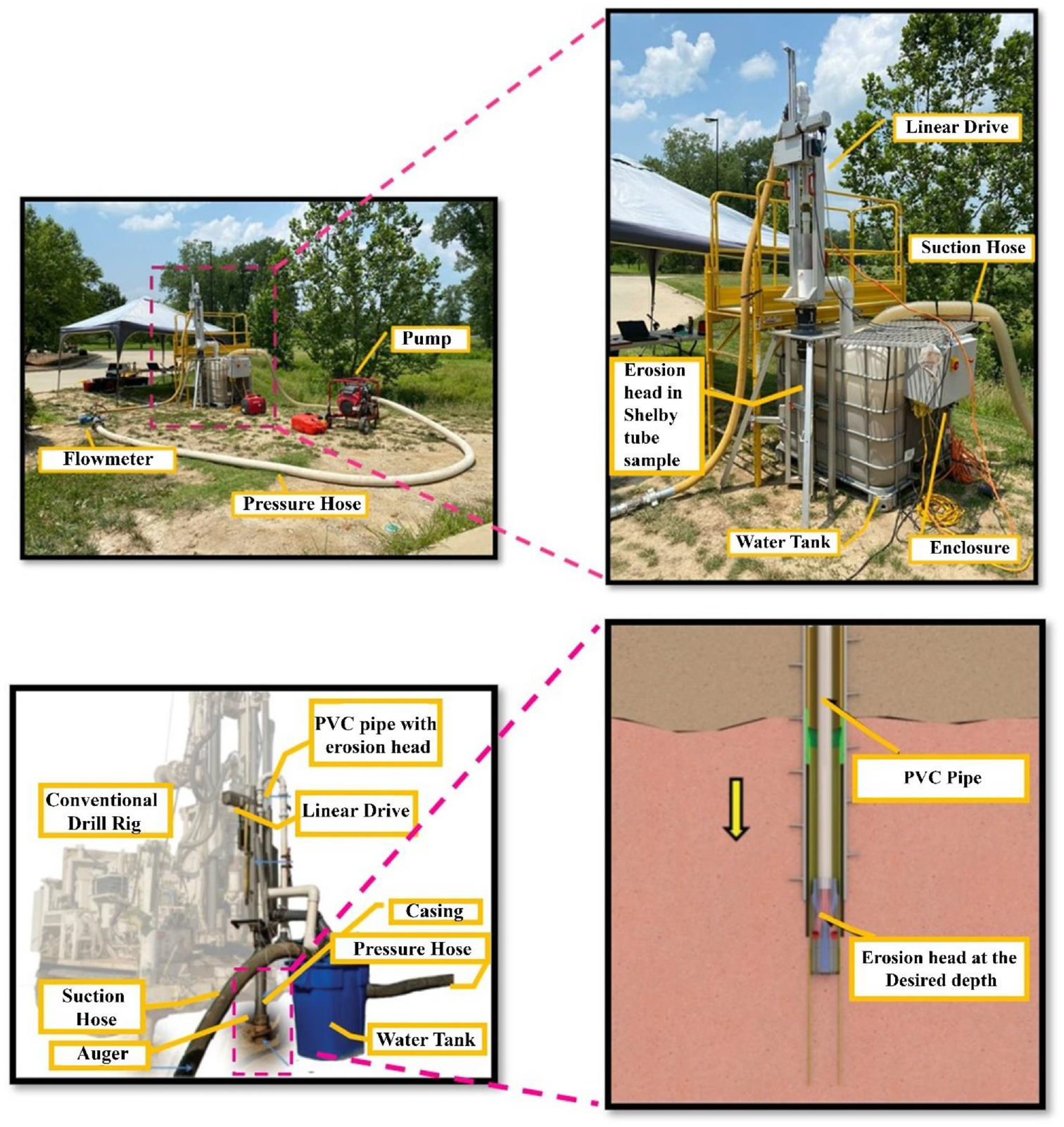
Top: Field set-up of portable scour testing device; Bottom: Field set-up of in-situ scour testing device ( 4 ).
The samples are collected using a Shelby tube sampler to obtain what is considered an undisturbed sample. The sampler does have some limitations in relation to the types of soils that the Shelby tube can be pushed into, with stiffer soils potentially damaging the sampler. Prior knowledge of soil type and stiffness through in situ tests would be helpful. For example, the standard penetration test (SPT), which measures the number of blows (i.e., N-value) to penetrate the soil in situ, or a Cone Penetration Test (CPT), can be used to estimate the soil type and stiffness. In materials with N-values of greater than 15, it is difficult to push Shelby tubes without damaging them. If the soil contains gravels or other obstructions, the range of materials that can be sampled is less. At the higher N-values the drillers will need to slow down when pushing the sampler to allow the sampler to penetrate the material.
The final boring depth for conducting ISTD in cohesive soils is based on the erosion resistivity characteristics of the material and the pump/system capacity. For deeper sampling depths, the ISTD pump system must overcome larger head losses to generate sufficient flow rates to erode soils at the erosion head. The stronger the material, generally speaking, the higher the flow rates that are required to erode the material. This inability to sustain enough pressure to overcome head losses limits ISTD to effectively run the test up to 12 to 18 m (40 to 60 ft) depth depending on the soil’s resistance to erosion. It is worth noting that the hydraulic system can handle a maximum flow rate of approximately 15 liter per second (0.53 cfs). The PSTD/ISTD is conducted inside an 89 mm diameter by 0.9 m long Shelby tube. The Shelby tube needs to accommodate a minimum of 0.45 m in length for the erosion head. In the PSTD test, the Shelby tube is pushed approximately 750 mm (2.5 ft) and then the extra material from the retrieved sample is removed and collected from the top, which is then used for material classifications.
Important Factors
As it would be for any project site assessment, the basic reconnaissance of a project area for geotechnical explorations that are outlined in AASHTO R 13 should be followed. However, additional criteria for hydraulic modeling and ISTD/PSTD testing also should be considered. Important factors that should be considered for successful scour analyses using ISTD/PSTD are as follows and are discussed in more detail later:
Availability of historical subsurface information such as soil borings, CPT data, and laboratory testing data at the site.
Availability of groundwater elevation information.
Geospatial analysis.
Aerial imageries.
Proximity to a United States Geological Survey (USGS) streamflow-gaging station. (Note that this is needed for hydraulic modeling and not erosion tests).
Environmental concerns or concerns with handling the disturbed material.
Availability of high-resolution topography. (Note that this is needed for hydraulic modeling and not erosion tests).
Capability to conduct ISTD, PSTD, and drilling on site.
Prior scour analyses at the site of interest, if available, would be helpful for subsequent scour analyses comparison.
Sites with 3 m (10 ft) predominant cohesive soil, and SPT N-values preferably less than 15.
A critical part of reaching a final decision is to understand the relative importance of each criterion to the others. As shown in Figure 2, along with geotechnical and hydraulic suitability, the site access should also be studied. Available subsurface information, such as historic borings, is useful in this phase. If such information is not available, drilling bore holes, sampling soils, and conducting SPT tests is suggested. Supplemented CPT tests would be ideal. The boring logs and CPT results should be evaluated to identify cohesive materials and their strength within the drilling depth. It should be noted that the materials with SPT N-values of more than about 15 are typically hard to sample with a Shelby tube. At sites that have buried pieces of wood, gravel, or stiff clay present, the Shelby tubes may be damaged, and sampling becomes difficult. Also, running PSTD/ISTD in soils that have wood pieces and coarse-grained material, even if possible, may provide erroneous results. The groundwater elevation (GWE) is important in site selection because saturated soils erode consistently and represents the condition of the soil during erosion ( 6 ). Dry samples have a tendency to slake during erosion tests, where the clay essentially disintegrates when exposed to water. As it is likely more convenient to conduct the subsurface investigation and PSTD/ISTD on the riverbanks and sides of the bridge area, the initial drilling will likely be through the bank material. The Shelby tube sampling depths for PSTD/ISTD, if possible, should be below the groundwater table because the intention is to evaluate the erosion characteristics of the materials at or below elevations that water-induced shear stresses result in erosion of soil surface, for example, the riverbed.
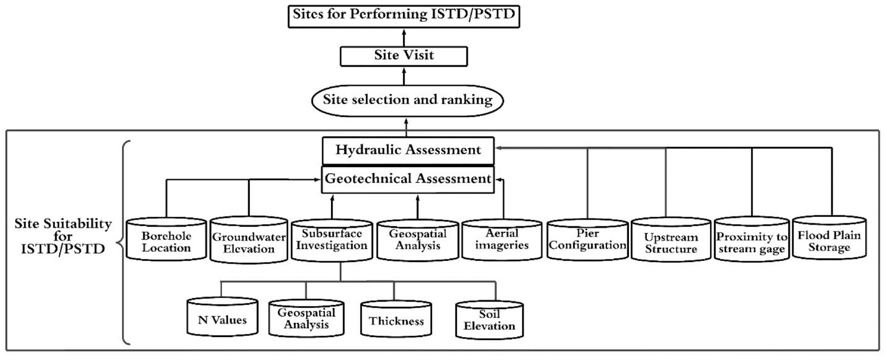
Framework for selecting locations for performing in-situ scour testing device (ISTD)/portable scour testing device (PSTD) testing.
In the next step, the potential spots for conducting the PSTD/ISTD test should be identified. This should involve using geospatial mapping, GIS modeling, and aerial imagery to locate an area where the terrain allows access for drill rigs. Therefore, an area with a steep slope or far from access roads is typically avoided unless track-mounted, all-terrain vehicle or other suitable drill rigs are available. To make the site accessibility evaluation process simpler, the three geospatial attributes of the aerial image, that is, hillshade, slope angle, and slope aspect can be utilized. An example of these will be discussed for a site in Illinois (i.e., site A). The slope angle is extremely useful because it displays the slope of the bridge abutment, steep slopes, and flat areas. Finding and referencing an abutment in an aerial view can be helpful in transferring the boring locations to geospatial maps because historical boring locations sometimes are difficult to transfer to geospatial maps because of lack of borehole GPS locations. The slope aspect displays the slope orientation, which is useful for indicating the direction, and the hillshade represents the topography of the area.
The hydraulic factors such as floodplain storage, upstream structure, pier configuration, stream power, and proximity to USGS streamflow-gaging stations should also be studied (see Figure 2). Following evaluation of a site’s feasibility per geotechnical and hydraulic aspects, a site visit should be performed to assess site access, select testing location(s), confirm the suitability of the selected sites, and stake the borehole locations. Potential barriers to site access, such as proximity to overhead and buried utilities like power and gas lines, the potential for flooding, traffic control requirements, availability of space for drill rigs and trucks, steep slopes, and the presence of drainage ditches, guardrail, trees, and bushes should all be considered during the site visit.
Hydrological data and history of prior scour play a role in site selection, if they are available. This information can determine the scour-prone bridges and the importance level of each site ( 7 )
Case Studies
Straub and Over and Straub et al. initially estimated the scour depth prediction of 30 bridge sites across Illinois using laboratory methods ( 8 , 9 ). These studies contained useful information such as soil boring data and groundwater elevation; therefore, their research was considered to create an initial list of potential ISTD/PSTD tests sites. Three of these 30 sites are discussed in this paper to show the implementation of assessment criteria discussed earlier.
The preparation of subsurface profiles using stick logs with depth, N-values, groundwater elevations, soil types, and soil layers with approximate thicknesses for each site is helpful in understanding of subsurface characteristics. Figure 3 shows the interpreted subsurface profile for site A in northern Illinois, which includes six boring logs. Figure 3 shows groundwater level readings, if obtained, at three different times: first encountered, on completion of drilling, and after more than 48 h. All boring logs for site A include clay and silt layers, with the exception of borings B1 and B3, which show sandy layers within the desired testing depth range. Therefore, the areas around borings B1 and B3 that have non-cohesive soils should be avoided. The area around boring B15, B2, B4, and B16 can be possible candidates for conducting PSTD/ISTD testing.
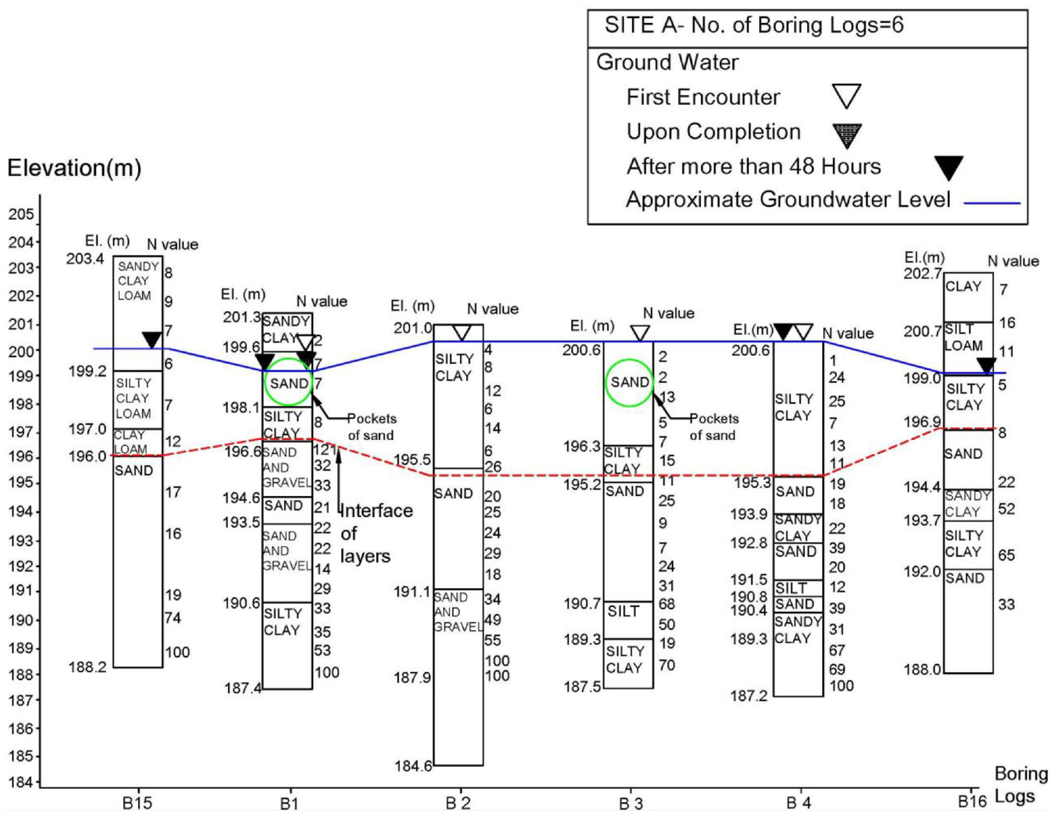
Subsurface profile at site A.
Figure 4 shows the subsurface profile with stick logs for site B located in the southwest of Illinois. At this site, the borings show layers of silty clay, silt, and sand. The top layer is composed of silt and silty clay from 129.5 to 137 m elevation. This upper layer is overlaid on a sand/gravel layer with the elevation ranging from 118 to 129 m. As the groundwater elevation is below the cohesive soil layers, conducting PSTD/ISTD testing is not recommended at this site.
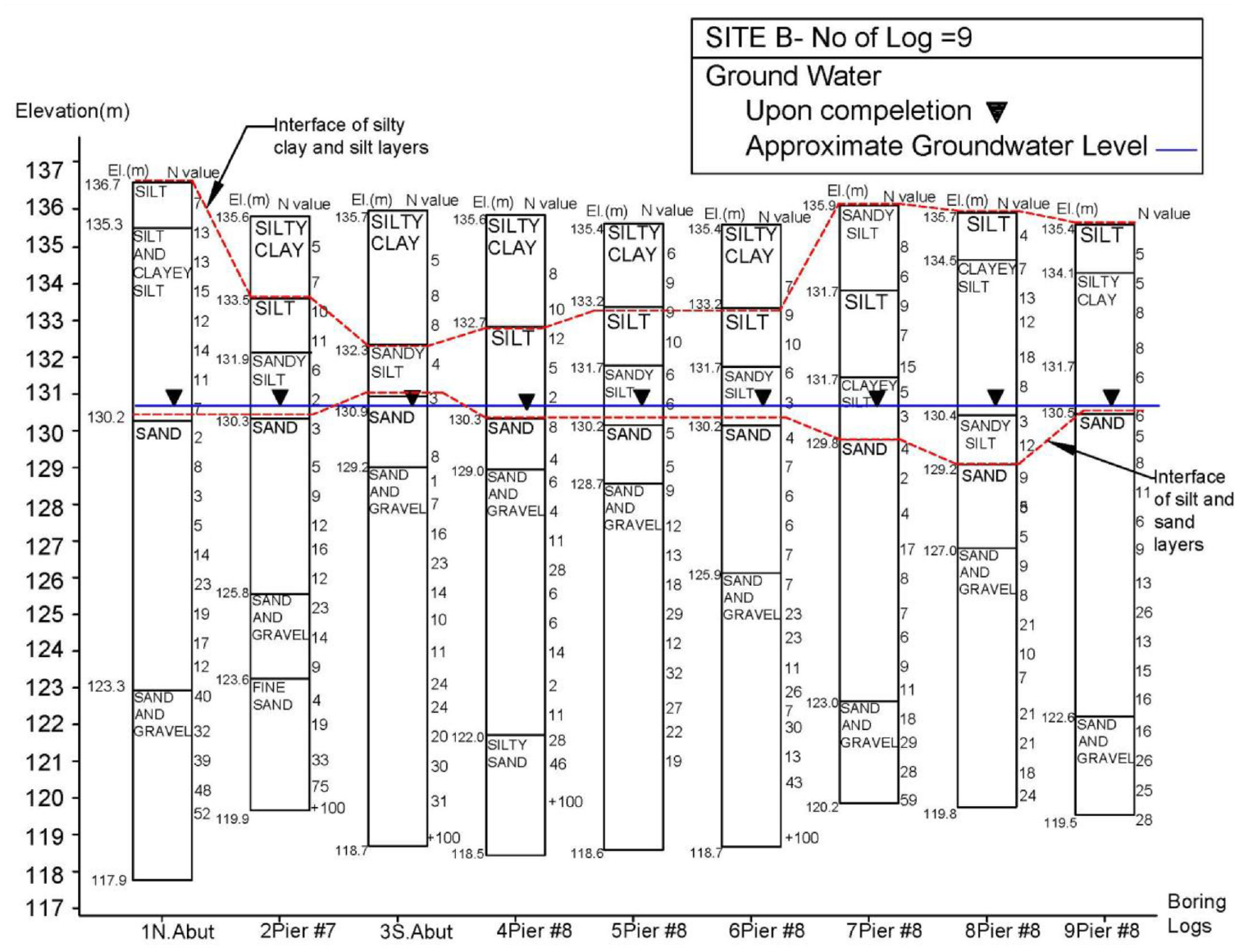
Subsurface profile at site B.
Site C, as shown in Figure 5, contains two borings that encountered cohesive layers below the groundwater table at the elevation of 197 m. Although the site might be a good candidate, the main challenge at site C is that the SPT N-values are in the 30s or higher. This indicates that pushing Shelby tube samples into the soil will be difficult, if not impossible. It should be noted that for both ISTD and PSTD tests, the Shelby tube should be pushed into the soil.
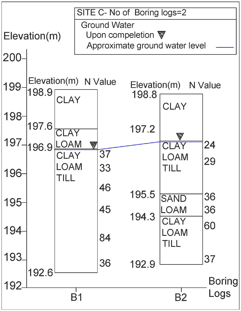
Subsurface profile at site C.
In addition to evaluating subsurface soil conditions, site accessibility should also be considered. Figure 6 illustrates the geospatial maps of the slope angle, aspect, aerial imagery, and hillshade features for site A. Figure 6a shows the terrain slope angle. As the bridge abutment and river edges have slope angles ranging from 64 to 84 degrees (see Figure 6a), the abutment and river edges are easy to identify. This allowed for positioning the historical boring locations without latitude and longitude recorded. As illustrated in Figure 6a, the area surrounding boring B4 is not selected for conducting the test because of the presence of a steep slope. The remaining bore holes are located in areas with mild slopes. Figure 6b shows the slope aspect map which also helps to locate the abutments and river edges. Figure 6c shows the aerial map and a potential location for conducting PSTD/ISTD tests and boring locations. This map shows that all borings appear to be located in drillable areas for conducting the test except B15, which is located among the trees and bushes. The results of the hillshade feature obtained from the geospatial analysis are shown in Figure 6d. The light and shadow patterns in the hillshade represent the sharp edges on the surface of site A. As illustrated in Figure 6d, the area surrounding borings B15 and B1 does not appear to be drillable, as this confined area surrounded by sharp edges is too small for setting up PSTD/ISTD devices. Where the suitable areas are difficult to find, it might be possible to set up the PSTD away from the testing area and bring Shelby tubes over to the PSTD location. Overall, the combination of geospatial and subsurface profile findings for site A suggest that the area around borings B16 and B2 is more likely to be a possible candidate to perform PSTD/ISTD testing.
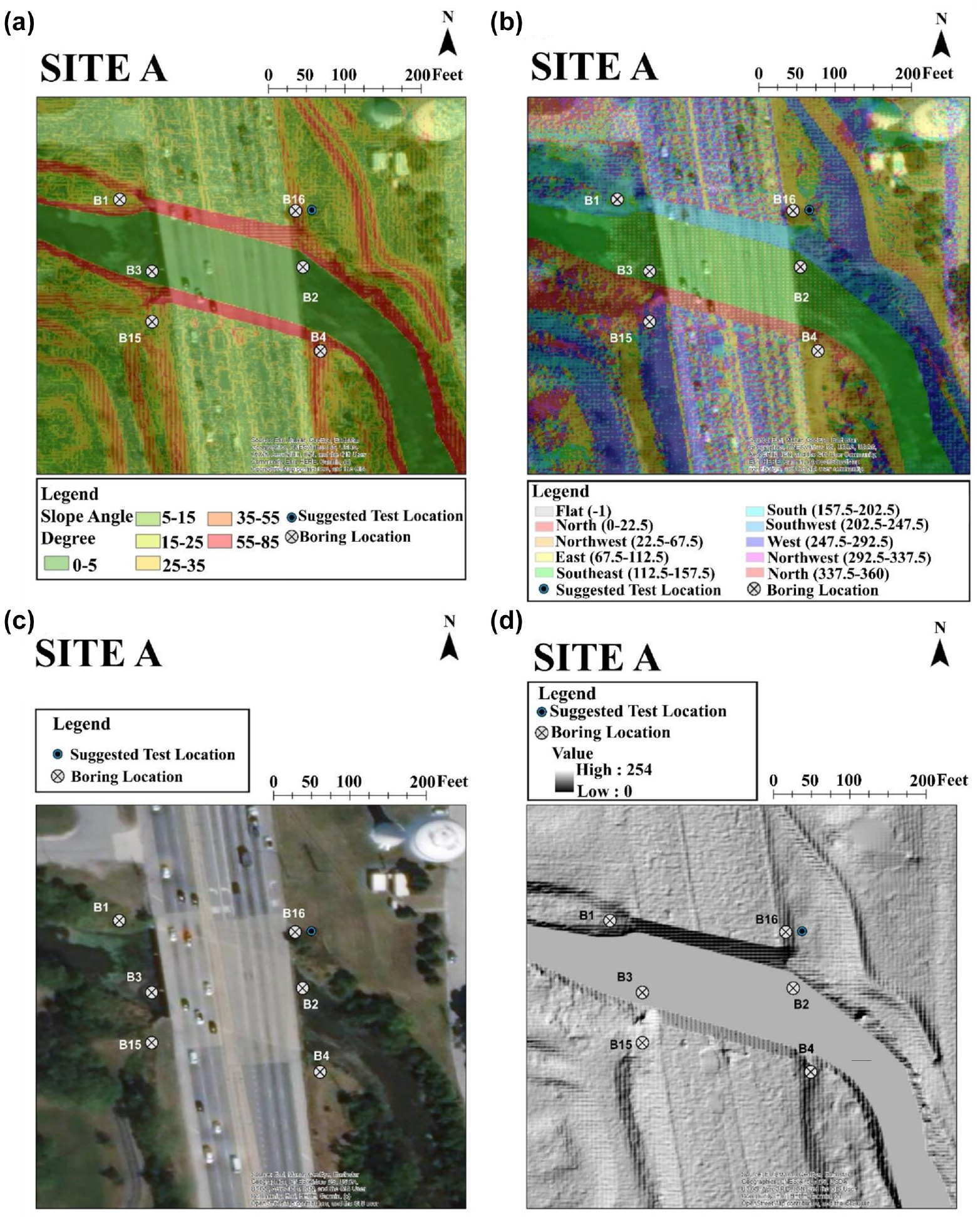
Visual delineation of morphometric features for site A: (a) slope angle, (b) slope aspect, (c) aerial photograph, and (d) hillshade.
Field Testing and Coordination Planning
Timing of the ISTD/PSTD field testing within a project should be coordinated to work with the hydraulic modeling process for new or existing bridges. Provided that sufficient existing information is available, such as historical borings, ISTD/PSTD field testing may need to be performed in advance of a geotechnical subsurface investigation for the bridge structure foundation design. PSTD/ISTD testing consists of assembling the PSTD/ISTD at a site, performing the PSTD/ISTD testing, and disassembling the components. The assembling, which can take up to 2 h for two persons, includes filling a tank with water, positioning the PSTD/ISTD parts, connecting the hoses, connecting the cables to the enclosure, adjusting the erosion head position and linear drive. The PSTD/ISTD test duration is highly dependent on soil type and its corresponding erosion rate. For example, a 450 mm-thick sandy soil material with an erosion rate of 2 mm/s takes 225 s to fully erode, whereas a 450 mm-thick clayey soil sample with an erosion rate of 0.15 mm/s takes 3,000 s. Disassembly of the PSTD/ISTD, which can take up to 1 h, entails draining the water, closing all valves, detaching the hose, pulling out cables, and repacking the components in the trailer.
Additionally, PSTD/ISTD testing requires team coordination among drilling crews and those who will be doing PSTD/ISTD testing. The use of 89 mm (3.5 in.) Shelby tubes, required for ISTD/PSTD, is not standard for sampling for most drill crews. Therefore, matching the drive head and necessary adaptors should be coordinated in advance. ISTD tests are conducted using casings with 101 mm (4 in.) outer diameter and the ISTD drilling requires 107 mm (4.25 in.) minimum inner diameter (ID) hollow stem augers or casing. To conduct the PSTD/ISTD testing, 0.45 m (1.5 ft) of a 0.9 m (3 ft) Shelby tube is needed to provide room for placing the erosion head within the Shelby tube. As some of the soil in the sample may be lost during Shelby tube extraction from the hole, it is advised to collect a full 750 mm Shelby tube sample to allow for expansion of the sample and then excavate the top part to allow placement of PSTD’s erosion head. This upper material can be collected to conduct testing to classify the material. Also, it is suggested to test the bottom of the tube with a pocket penetrometer, Torvane, or both, to get an index of the stiffness of the material being tested.
An understanding of the sampling requirements is important for planning purposes. There will be two groups of Shelby tube samples needed. The first group of samples is used to conduct the PSTD field test. To perform the PSTD field test for a 0.9 m (3 ft) layer, at least two adjacent holes need to be drilled because only half of the Shelby tube soil sample can be tested because of the ISTD/PSTD constraints discussed above. The second group of Shelby tube samples is collected to conduct the laboratory tests which can include classifications, strength, permeability, and consolidation. The purpose of these samples is to correlate the erosion test to the conventional geotechnical parameters. These data can also be used for the bridge foundation design or remediation of existing bridge foundations. The number of boring samples that must be drilled is determined by the number of tests that must be performed. It is ideal to drill one boring for conducting ex situ scour testing device (ESTD) ( 6 ) or erosion function apparatus (EFA) ( 10 ) tests. The EFA and ESTD are performed in the lab to measure erodibility characteristics for erosion studies. Table 1 presents an overview of the estimated number of Shelby tube samples needed for subsequent laboratory testing depending on the needs of the project. As shown in Table 1, the soil laboratory tests include Atterberg limits, particle size distribution with hydrometer testing, specific gravity, unconfined compressive strength (UCS) testing, unconsolidated undrained (UU) triaxial testing, EFA, and ESTD. This table shows the approximate number of Shelby tubes needed per 3 m (10 ft) layer for laboratory tests.
Shelby Tube Sampling Planning for Laboratory Testing
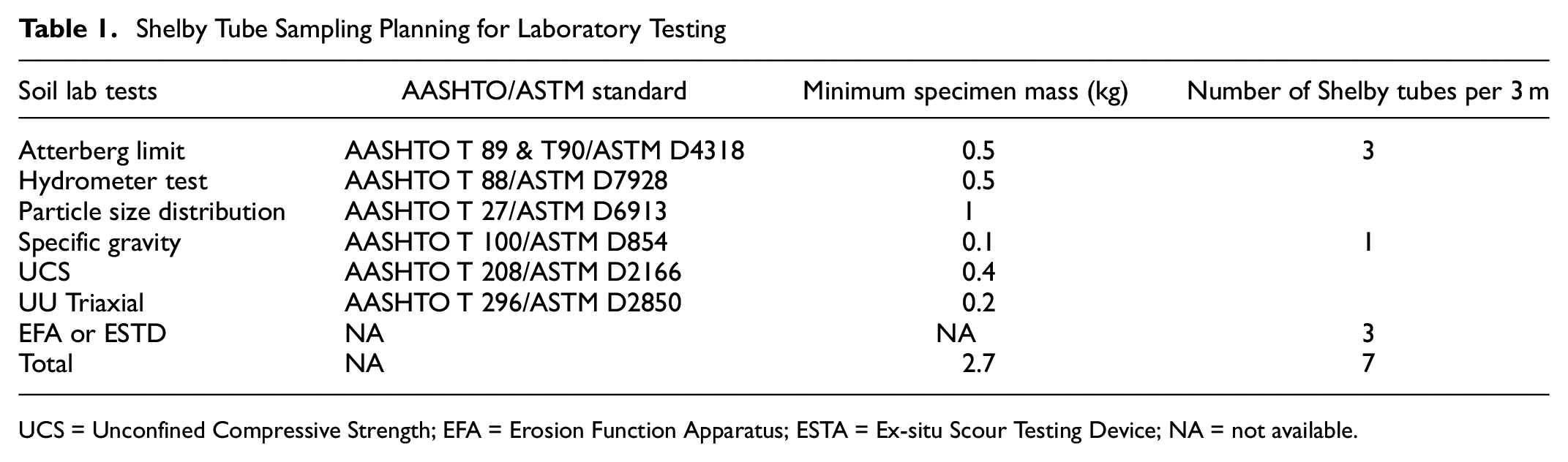
UCS = Unconfined Compressive Strength; EFA = Erosion Function Apparatus; ESTA = Ex-situ Scour Testing Device; NA = not available.
Conclusions
The PSTD/ISTD has the potential to become a useful tool for assessing scour depth and designing more cost-effective bridge foundations by reducing conservativism in scour depth estimation for cohesive soils. Site suitability determination and thoughtful planning for the field testing are key steps needed for successful execution of PSTD/ISTD testing and using the results in hydraulic modeling. An overview of an initial set of criteria used to assess site suitability for conducting PSTD/ISTD testing per geotechnical and hydraulic considerations was presented. Some limitations, capabilities and logistical requirements of running PSTD/ISTD were discussed. Three case studies were discussed to demonstrate how the proposed multi-criteria assessment framework may be used for site selection. This study also demonstrates that GIS modeling can be a powerful tool for site reconnaissance. Moreover, the logistical coordination of field activity and scheduling were discussed along with an overview of developing a field sampling plan for conducting associated laboratory testing.
Footnotes
Author Contributions
The authors confirm contribution to the paper as follows: study conception and design: A. Osouli, D. Alzamora; data collection: M. Ebrahimi, H. Shoup; analysis and interpretation of results: A. Osouli, M. Ebrahimi, D. Alzamora.; draft manuscript preparation: A. Osouli, M. Ebrahimi, H. Shoup, D. Alzamora, J. Pagenkopf. All authors reviewed the results and approved the final version of the manuscript.
Declaration of Conflicting Interests
The author(s) declared no potential conflicts of interest with respect to the research, authorship, and/or publication of this article.
Funding
The author(s) disclosed receipt of the following financial support for the research, authorship, and/or publication of this article: This publication is based on the results of ICT R27-220: Developing Scour-Depth Estimation Using the In Situ and Portable Scour Testing Device (ISTD and PSTD) for Illinois Cohesive Soils. ICT R27-220 was conducted in cooperation with the Illinois Center for Transportation; the Illinois Department of Transportation, and the US Department of Transportation, Federal Highway Administration.
Data Accessibilitty Statement
The data that support the findings of this study are available from the corresponding author, on request.
Unless noted otherwise, authors of this technical paper, are the source for images in this paper. The contents of this report reflect the view of the authors, who are responsible for the facts and the accuracy of the data presented. The contents do not necessarily reflect the official views or policies of the Illinois Center for Transportation, the Illinois Department of Transportation, or the Federal Highway Administration. This report does not constitute a standard, specification, or regulation.