
Abstract
This paper reports the details of a computationally efficient finite element analysis code (called MatFEA), designed specifically for flexible pavements, where stress-dependent characteristics of unbound layers are considered. The stress-dependent nonlinearity of the unbound materials has been modeled in MatFEA through an iterative approach. MatFEA was mainly developed to improve the Mechanistic-Empirical Asphalt Pavement Analysis (MEAPA) web application with capability of analysis/design of nonlinear pavement structures. A specific-purpose mesh generation algorithm was developed for the MatFEA in which the mesh density was dynamically adjustable based on the expected stress magnitude. To verify the results of the MatFEA, 12,000 nonlinear pavement structures with different structural and loading properties were generated and analyzed with MatFEA. The same pavement structures were modeled in a general-purpose FE-based ABAQUS™ program. The results of this study showed that the critical pavement structural responses from the MatFEA were almost identical with those modeled by ABAQUS™ program. The average runtime of MatFEA for analyzing each pavement structure was about 1.13 s. Finally, it was concluded that application of the dynamically adjustable mesh generation algorithm in the MatFEA helped achieve a reasonably high accuracy as well as efficient runtime, which brings the advantage of implementing the MatFEA as a pavement structural response model in the mechanistic-empirical pavement analysis/design procedures.
Keywords
Flexible pavements are multi-layer structures mainly consisting of asphalt concrete (AC) in the top layers, unbound granular aggregates in intermediate layers and unbound fine-grain soils in lower layers or subgrade. The response of pavement structure to different traffic tire loads is a key factor in the mechanistic-empirical (ME) pavement design procedures. Two common pavement structural analysis methods are: layered elastic analysis (LEA) and numerical finite element (FE) analysis.
The current procedure of ME pavement design uses LEA-based software for calculation of pavement responses ( 1 , 2 ). Thus, although the AC layer at low strain levels is well known to act as a linear viscoelastic material, for pavement design purposes, it is still considered as a linear elastic layer. However, the viscoelastic behavior of AC is indirectly taken into account by computing an equivalent elastic modulus from the complex (dynamic) modulus (E*) master curve of the AC layers. In this procedure, AC layers are divided into several sub-layers, where the elastic modulus of each asphaltic sub-layer is estimated from its E* master curves based on duration of applied traffic load and temperature gradient, calculated by enhanced integrated climatic model (EICM).
On the other hand, almost all LEA methods assume a linear elastic behavior for unbound granular aggregates and fine-grained soils in non-asphaltic layers. For example, Michigan Department of Transportation (MDOT) practice is to assume an elastic modulus of 33,000 pounds per square inch (psi) for unbound granular base and 20,000 psi for sand subbase layers during pavement design using the AASHTOWare Pavement ME software ( 3 ). However, it is well known that the behavior of unbound granular materials and fine-grained soils are nonlinear (stress-dependent) under traffic tire loads ( 4 – 6 ). This nonlinearity significantly affects the calculation of critical pavement responses ( 7 , 8 ). The main reason for not including nonlinear behavior in pavement design and analysis software is that, without a finite element analysis (FEA) core engine, nonlinearity of base, subbase and subgrade layers cannot be accurately modeled. Since the existing FEA algorithms are computationally inefficient (compared with LEA algorithms), the pavement research community has historically accepted the simplification of unbound material nonlinear behavior into an elastic material. There is a need for computationally efficient FEA engines so that the true nonlinear behavior of unbound layers can accurately be considered in pavement design and analysis applications.
The objective of this study was to develop a reasonably accurate and computationally efficient FE-based pavement analysis framework, called MatFEA, in which the nonlinearity of unbound materials is included. The ultimate goal for this effort was to enhance the Mechanistic-Empirical Asphalt Pavement Analysis (MEAPA) web application (https://paveapps.com/meapaapp3/) so that MatFEA is used as the main pavement structural response model when nonlinearity of unbound materials needs to be considered ( 1 , 9 ).
Modeling Methods for Unbound Material Nonlinearity
Cyclic loading tests are typically used to characterize the behavior of unbound materials ( 10 ). For an unbound material, it is well known that plastic deformation occurs during initial loading cycles, which tends to stabilize at a certain level as the number of cycles grow. This phenomenon is called shakedown, which can take place in the construction and initial traffic passing stages. After shakedown occurs, the unbound material exhibits steady state and elastic strain response by which the resilient modulus (MR) at the applied load level is defined:

where MR is the resilient modulus of unbound material (psi), σd is the applied deviator stress (psi) in a triaxial test and εr is the recoverable strain after shakedown. The MR value of unbound materials depends on the applied stress. Unbound granular materials mainly exhibit stress-hardening behavior ( 4 , 6 , 11 ), where the MR values increase as the load level increases, while fine-grained soils often exhibit stress-softening behavior ( 5 , 11 , 12 ) where MR decreases with increasing stress state. Hicks and Monismith ( 13 ) developed the so-called K-θ model for unbound granular materials by which the MR is a nonlinear function of bulk stress, as shown in Equation 2.

where K1 (psi) and K2 are model coefficients and θ is the bulk stress (psi), which is calculated as:

where σr, σz, σθ are radial, vertical and tangential stresses (psi) at the point of interest; K0 is the coefficient of earth pressure at rest; γ is the unit weight of the sample (pounds per cubic inch) and z is the depth from the top of sample (inches). It should be noted that tensile stress components (after adding the effect of earth pressure) are assumed to be zero as they do not cause any confinement. As the K-θ model is a single stress component model based on the bulk stress, it cannot incorporate the effect of shear stress on the predicted MR value. This could cause limitation for pavement structures with relatively large shear stresses.
Witczak and Uzan ( 14 ) introduced a universal model by incorporation of the effect of deviatoric and shear stresses via octahedral shear stress (τoct), as shown in Equation 4. Since τoct covers the material stress states in all directions, this model has gained more attention for use in the three-dimensional (3D) analysis of nonlinear pavement structures.

where pa is the atmospheric air pressure (≈14.706 psi), K1, K2 and K3 are the model coefficients and τoct is the octahedral shear stress (psi), which is calculated as:

where J2 is the second invariant of stress (psi 2 ) and is calculated for an axisymmetric geometry using Equation 6.

where σrz is the shear stress (psi). Similar to the calculation of bulk stress, the tensile stress components (after adding the effect of earth pressure) are assumed to be zero, since unbound materials do not take tension. Later on, the universal model was modified during the NCHRP 1-37A project, as shown in Equation 7 ( 2 ). The modification of adding “+1” to the shear softening term of universal model was added to avoid the effect of zero deviatoric shear stresses, as the K3 exponent is negative.

where all the parameters are previously defined. The NCHRP 1-37A model for nonlinear unbound granular materials was planned to be used in MEPDG, but never implemented in the AASHTOWare Pavement ME software, because of the computational inefficiency of the FE engines available at the time ( 2 ).
The MR of fine-grained soils is often believed to have stress-softening behavior as a function of deviator stress (σd). Several mathematical models have been proposed for representing the MR of subgrade soils ( 15 ), among which the bilinear model ( 16 ), which is another single stress component model based on deviatoric stress, has been mostly utilized in the pavement community, as shown in Equation 8.
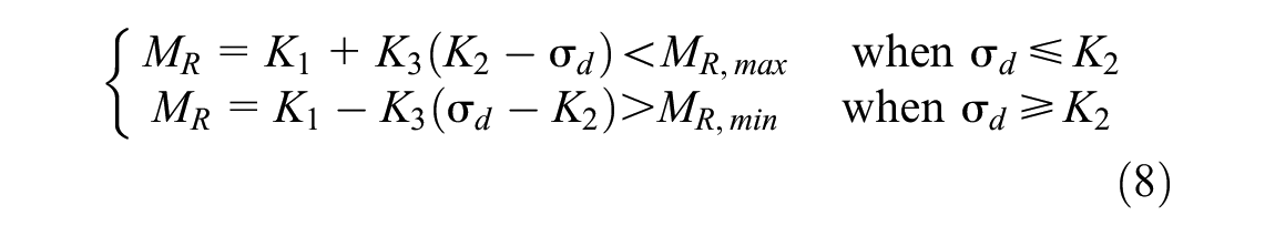
where MR,max and MR,min are the maximum and minimum MR values (psi), and K1, K2, K3 and K4 are the model regression coefficients. Several studies have investigated the existence of a correlation between the MR model coefficients and soil properties such as gradation, density, moisture content, porosity and so forth ( 4 , 11 , 12 , 17–20).
Although the MR and Young’s modulus (E) are different in nature, the use of MR instead of E for linear elastic layers is a common practice during pavement structural analysis. The reason is that an unbound material experiences its shakedown stages during construction and initial traffic, which means the behavior of unbound materials under regular traffic loading can reasonably be assumed to be purely elastic.
Pavement Structure Analysis Programs
Burmister ( 21 ) developed a theory of layered elastic solution for analysis of two- and three-layered pavement structures in which pavement layers are assumed to be homogeneous, isotropic and linear elastic. This theory was later extended for an arbitrary number of pavement layers, where each pavement layer is represented by its elastic modulus (E), Poisson’s ratio (ν) and thickness. This theory can only model a single circular tire loading with a uniform contact pressure.
Several LEA-based pavement analysis softwares have been developed including: ELSYM5 ( 22 ), WESLEA ( 23 ), VESYS ( 24 ), KENLAYER ( 25 ) and others. The repeated analysis of pavement structure in the ME pavement design procedure has led to several improvements to increase the computational efficiency of LEA-based software: MnLayer ( 26 ), ERAPAVE ( 27 ) and MatLEACANGG ( 28 ) can be listed in this regard.
Although the layered elastic theory was developed based on linear elastic behavior, the nonlinearity of materials may also be approximated through an iterative process. Huang ( 25 ) incorporated the nonlinearity concept into the KENLAYER software by iteratively adjusting the elastic modulus of the nonlinear layer based on the stress states of a specific stress point within that layer. Huang suggested using a point at the mid-depth of each nonlinear layer, called the stress point. To increase the accuracy of this approach, the nonlinear layer was divided into several sub-layers of about 2 in. thickness. The same approach is used by ERAPAVE and MatLEACANGG. As pavement layers are assumed to be homogeneous in both horizontal and vertical directions, the calculated nonlinear pavement responses are expected to diverge from actual responses at locations radially further away from the stress point. Therefore, Huang ( 25 ) recommended locating the stress point under the tire load when the maximum stresses and displacements are required or using his proposed formulation for radial distances for calculation of average responses. Varma and Kutay ( 29 ) also suggested the use of 3.5 times the loading contact radius for the radial distance of stress point from the axis of symmetry. The authors of the current paper conducted extensive runs of LEA-based approximate nonlinear methods (e.g., Huang [ 25 ], Varma and Kutay [ 29 ]) and compared the results with ABAQUS™ nonlinear runs. It was observed that although the LEA-based approximate nonlinear methods are reasonable in some cases, they diverged from the results of nonlinear modeling in ABAQUS™ in many other cases.
Unlike the LEA approach, the FE approach is a mechanistic solution for analyzing the pavement structures by which the nonlinear and/or anisotropic material behavior can be considered. In the FE approach, the pavement structure is divided into a finite number of elements where any specific constitutive model behavior can be defined for each of them. Considering the pavement structure and circular load geometry, two-dimensional (2D) axisymmetric FE solutions have been a common practice for analysis of pavement structures. Such 2D axisymmetric FE solutions are simpler to model and more computationally efficient compared with 3D solutions. ILLI-Pave ( 30 ), MICH-Pave ( 31 ), GT-PAVE ( 32 ) and C-FLEX ( 33 ) are some of the well-known FE-based pavement analysis softwares which are based on 2D axisymmetric solution.
Two-dimensional axisymmetric FE solutions can only model a single tire loading. Although the superposition concept has been extensively used to consider the effect of multiple tire loadings with LEA solutions, it is not used with 2D axisymmetric FE models. This is while full 3D FE models have been extensively used to model the nonlinearity of pavement structure under multiple tire loading more realistically. Therefore, several specific-purpose 3D FE pavement analysis programs have been developed, including SAFEM ( 34 ), CAPA-3D ( 35 ) and others. On the other hand, several studies have used the general-purpose FE softwares, such as ABAQUS, ANSYS and ADINA, for 3D modeling of pavement structures with different material behaviors and various loading conditions ( 7 , 8 , 29 , 36 , 37 ). It has been reported that the computational runtime for analyzing nonlinear pavement structure significantly increases with the use of 3D FE solutions compared with the 2D axisymmetric ones ( 7 , 38 ), which makes the implementation of 3D FE solutions for the pavement design procedures impractical.
Development of MatFEA
MatFEA has been developed as a modularized MATLAB code to efficiently analyze pavement structures with nonlinear unbound layers through the FE approach. It can model the nonlinearity of unbound materials based on the models discussed above. Figure 1 shows the analysis logic of MatFEA in a flowchart. Analysis formulations, boundary condition, mesh generation algorithm and nonlinearity iterations are explained in this section.

Flowchart of pavement analysis in MatFEA.
Strain-Displacement Relationship
For an axisymmetric FE solution, the generic nodal displacement vector of each node within the r-z plane includes radial (u) and vertical (w) components. The differential strain-displacement relations for the axisymmetric solution are shown Equation 9.
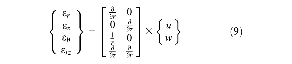
where εr is the radial strain, εz is the vertical strain, εθ is the tangential strain, εrz is the shear strain, r is the radial coordinate and z is the vertical coordinate. The stress vector is calculated using the strain vector using Equation 10.
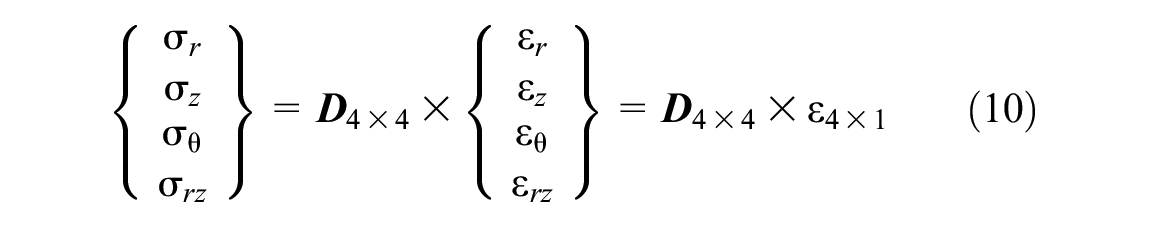
where σr is the radial stress (psi), σz is the vertical stress (psi), σθ is the tangential stress (psi), σrz is the shear stress (psi),

where E is the modulus of elasticity (psi) and ν is the Poisson’s ratio.
MatFEA uses four-node bilinear elements in which each node has two degrees of freedom for radial and vertical displacements. Therefore, the transfer matrix (

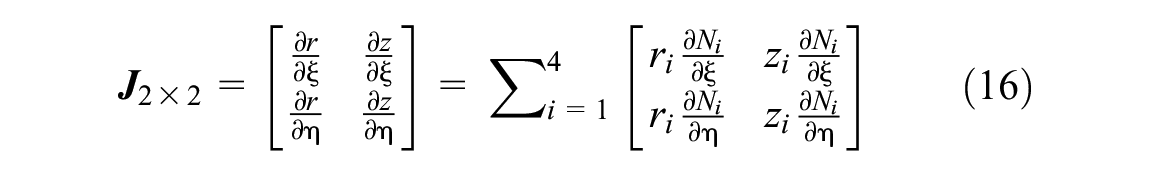
where Ni is the shape function of each node in the local coordinate system, ζ and η are the radial and vertical components of the local coordinate system and R is radial distance from the axis of symmetry, as shown in Equation 13.

where ri is the global radial coordinate of the ith node in each element (inches). The elemental stiffness matrix (

An isoparametric approach was then used to convert the global coordinate (r-z) to the local coordinate (ζ-η) system. Thus, the elemental stiffness matrix is represented as shown in Equation 15.

where
The Gaussian integration method with three Gaussian points was used to numerically calculate the elemental stiffness matrix, which was then combined together to form the global stiffness matrix (
As the tire loading is the only external load to the pavement structure, the magnitudes of nodal forces at the surface nodes within the loading area were calculated by multiplying the contact tire pressure to the corresponding loading strip area, as shown in Equation 17.

where i is counter of nodes on the pavement surface and within the tire loading area, Fi is the vertical nodal force applied to the ith node (pounds), CP is the contact tire pressure (psi), and rout and rin are the outer and inner radius of loading strip (inches), such that rout = (ri+1+ri) / 2 and rin = (ri−1+ri) / 2. Finally, the nodal displacements were calculated by applying boundary conditions and solving Equation 18.

where
Boundary Condition and Domain Size
Layered elastic theory uses the semi-infinite half-space assumptions in which the pavement structure extends to infinity in both vertical and horizontal directions. This infinite assumption is not implementable in FE solutions. Therefore, the boundary conditions and domain sizes of the FE model should be selected carefully to maintain the accuracy of the solution and avoid boundary edge errors.
According to the 2D axisymmetric geometry of the FE model, the structural roller support should be used on the inner vertical edge of the model. This will restrict the horizontal displacements but vertical displacement is allowed ( 39 ). Structural roller support was also used at the outer vertical edge of the model. The horizontal bottom edge of the model was supported by the structural fixed support, which restricts both vertical and horizontal displacements. The same boundary conditions have been used in the literature ( 7 , 8 , 29 , 30 , 33 , 36 ). Figure 2 shows a conceptual scheme of the boundary conditions in MatFEA.
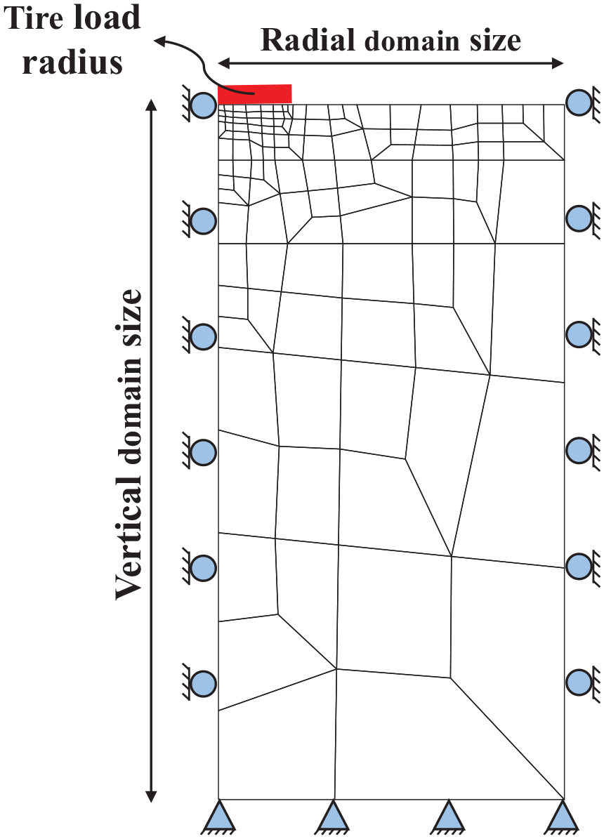
Boundary condition in MatFEA.
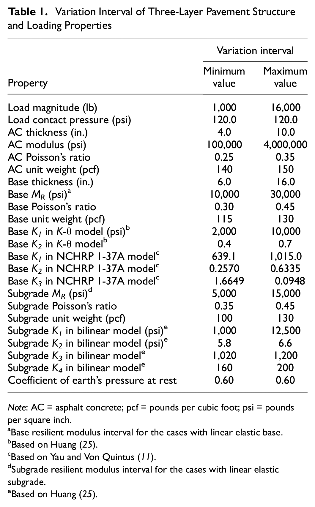
An appropriate domain size of the pavement structure in the FE model can minimize the effect of boundary conditions on pavement responses. Dehlen ( 40 ) recommended vertical and radial domain sizes of 50 and 12 times the loading radius. The same vertical domain size is also used in ILLI-PAVE ( 30 ). The vertical and radial domain sizes of 140 and 20 times the loading radius have been recommended based on comparison with the linear analytical solutions ( 7 ). Saad et al. ( 36 ) performed a domain size analysis by monitoring the maximum vertical strain at the top of the subgrade and maximum tensile strain at the bottom of the AC layer, while keeping the same mesh design. The same procedure was performed in the current study and the domain size of 150 and 40 times the loading radius was selected for the depth and radius of the pavement structure model in MatFEA.
Mesh Generation Algorithm
Mesh design is one of the most important factors affecting the efficiency of a FE solution. Application of coarse mesh reduces the number of elements which brings reduced computational runtime but less accuracy in pavement responses. Refining the mesh could also improve the solution accuracy while increasing the required computational effort.
The application of a 2D axisymmetric model for analyzing the pavement structure provides a simple rectangular layered geometry. Therefore, a recursive specific-purpose unstructured mesh generation algorithm was developed to generate four-node quadrilateral elements. In this algorithm, the mesh density is dynamically adjusted based on the expected stress state, that is, it generates fine mesh at the areas where high stress is expected close to the load centerline and gradually increases the mesh size as it approaches the bottom and outer boundaries. It is noted that this algorithm does not change the mesh from one iteration to another (see Figure 1) and the mesh density is pre-defined based on the distance from the pavement surface and load centerline. The algorithm also prevented the formation of irregular or rotated (diamond like) quadrilateral elements, as well as elements with aspect ratio of greater than 10. It has been reported that the calculated stresses from the quadrilateral elements with the aspect ratios of less than five are reasonably accurate ( 31 ). The main purpose for developing this mesh generation algorithm was to maintain the solution accuracy and computational efficiency simultaneously. An example of the mesh generated for a typical pavement structure is shown in Figure 3.

Mesh design in MatFEA.
Nonlinear Iterative Procedure
MatFEA uses an iterative approach for capturing the nonlinear behavior of materials. For this purpose, elemental stress responses were calculated by assuming an initial MR value for the elements in the nonlinear layers with the same materials. At each iteration, the MR of each element in the nonlinear layer was updated after running FE analysis based on the calculated stress responses and the corresponding nonlinear MR model. The relative difference in MR value (ΔMR) was then calculated for each element using Equation 19.

where MR,new is the updated elemental resilient modulus (psi) and MR,old is the resilient modulus of the previous iteration (psi). The elemental ΔMR values of all elements in a given nonlinear layer were statistically evaluated against the convergence criterion. This iterative procedure (see Figure 1) continued until the convergence criterion was satisfied.
The convergence criterion was defined as a mean ΔMR of all elements in the nonlinear layers at a specific reliability level, as shown in Equation 20.

where ψ is the mean value of ΔMR values at the specific reliability level (%), ZR is the normal deviate for the reliability level, μ and Std are the mean and standard deviation of the elemental ΔMR values for all elements in a nonlinearity layer (%), respectively. MatFEA uses the 95% reliability level (ZR = −1.645) and 2% convergence criterion under a maximum of 10 iterations.
Verification of MatFEA
ABAQUS™, a general-purpose FE analysis tool, was used to verify the accuracy of the MatFEA implementation. For this purpose, a database of 12,000 nonlinear pavement structures was randomly generated, which includes 3,000 pavement structures with nonlinear bases (K-θ model in Equation 2), 3,000 pavement structures with nonlinear bases (NCHRP 1-37A model in Equation 7), 3,000 pavement structures with nonlinear subgrades (bilinear model in Equation 8), and 3,000 pavement structures with both nonlinear bases (NCHRP 1-37A model in Equation 7) and nonlinear subgrades (bilinear model in Equation 8). Each pavement structure/loading property in this database was generated by selecting a random number within a pre-determined interval for the property of interest, as shown in Table 1. These pavement sections were then modeled through axisymmetric FE method using ABAQUS™ and MatFEA programs.
Variation Interval of Three-Layer Pavement Structure and Loading Properties
Note: AC = asphalt concrete; pcf = pounds per cubic foot; psi = pounds per square inch.
Base resilient modulus interval for the cases with linear elastic base.
Based on Huang ( 25 ).
Based on Yau and Von Quintus ( 11 ).
Subgrade resilient modulus interval for the cases with linear elastic subgrade.
Based on Huang ( 25 ).
To be consistent with the algorithm of the MatFEA, a Python script was developed to model each pavement section in the ABAQUS™ program and perform the nonlinearity iterations (instead of utilizing the user material [UMAT] Fortran subroutine). The ABAQUS™ models use a free mesh based on four-node first-order elements with reduced integration (CAX4R). The developed Python script consists of the following steps:
Model the pavement structure and applied pressure loading in an axisymmetric scheme;
Mesh the model such that the mesh is denser at the high stress areas;
Run the analysis for the initial model;
Perform iteration by adjusting the modulus of the elements in the nonlinear layers and re-running the model until the convergence criterion is met.
Four different critical pavement responses were compared against ABAQUS™ for verification of the MatFEA: maximum surface deflection, radial strain at the bottom of the AC layer, vertical strain at the middle of the base layer and vertical strain at the top of the subgrade. Commonly used statistical metrics were utilized for comparison purposes, including coefficient of determination (R 2 ) (Equation 21), mean absolute error (MAE) (Equation 22), root mean square error (RMSE) (Equation 23) and bias (Equation 24).


where Resp_MatFEAi and Resp_ABAQUSi are the structural responses for each pavement section using the MatFEA and ABAQUS™ programs and n is the number of pavement sections used for verification.
As the ABAQUS™ models are used for verification of the results of MatFEA models, a relatively denser mesh was used in ABAQUS™ models to assure higher accuracy of the pavement structural responses. In this regard, Figure 4 shows the distribution of the number of elements used for modeling each of the pavement structures in the database using the MatFEA and ABAQUS™ programs. As this figure shows, the mesh of ABAQUS™ models was about six times finer than in the MatFEA models.
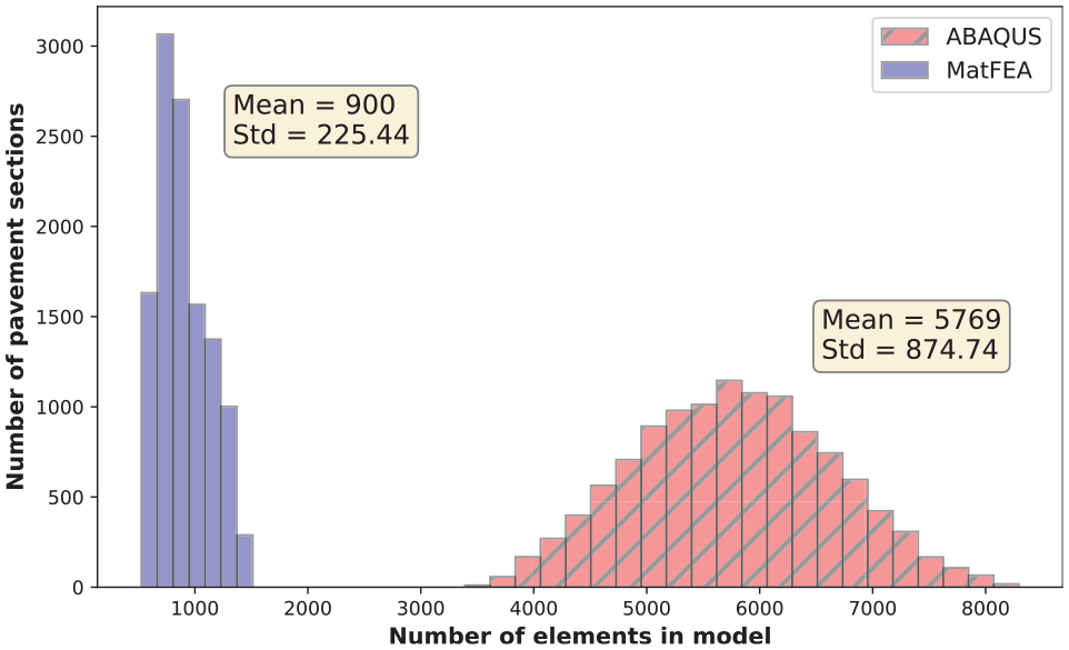
Distribution of number of elements used in modeling of pavement structures.
The equality graphs and calculated statistical metrics for comparing the results of MatFEA versus ABAQUS™ models for pavement structures in the database are shown in Figure 5. As this figure shows, almost all of the data points for all critical structural responses were clustered around the line of equality. This observation was supported with the statistical metrics, such as high R2, and considerably low MAE, RMSE and bias.
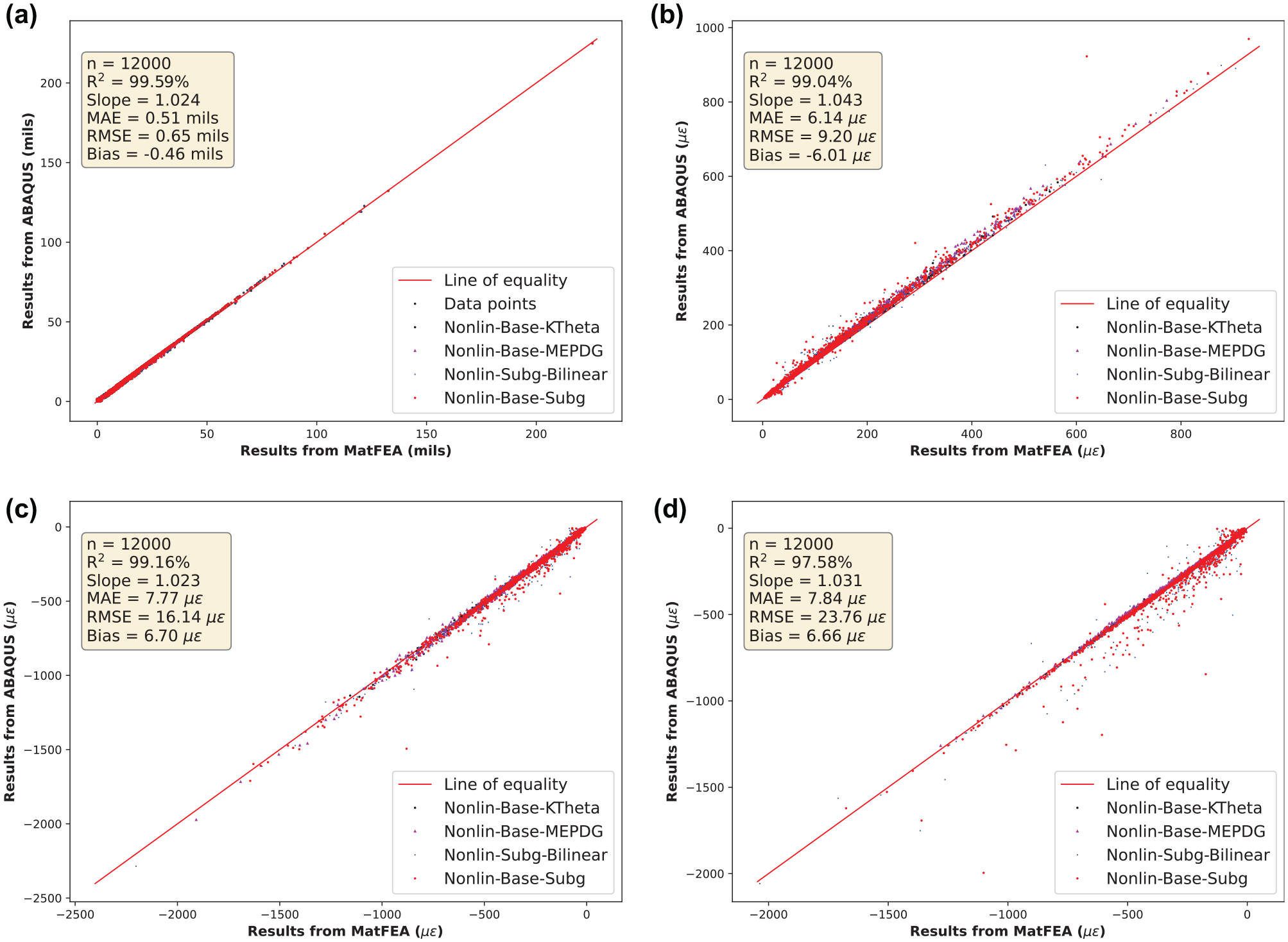
Comparison of pavement critical responses from MatFEA and ABAQUS™ models at: (a) maximum surface deflection, (b) radial strain at bottom of asphalt concrete layer, (c) vertical strain at middle of base depth, and (d) vertical strain at top of subgrade.
Although the pavement structures were modeled in ABAQUS™ in accordance with the main algorithm of the MatFEA, Figure 5 shows that the structural responses from MatFEA did not exactly match those from ABAQUS™. This can be attributed to the significantly finer mesh of the model in the ABAQUS™ program with which higher accuracy can be achieved. Moreover, a sensitivity analysis revealed that the best match between the ABAQUS™ and MatFEA models was achieved for the pavement structures with nonlinear bases (either the K-θ or NCHRP 1-37A models), while some divergences were observed in vertical strains at the top of the subgrade for pavement structures with nonlinear subgrade (bilinear model).
It is noted that the average runtime of the MatFEA for 12,000 pavement structures in the database was about 1.1 s, while the average runtime of each ABAQUS™ model was about 227.8 s. The significantly higher runtimes of the ABAQUS™ models were the result of their finer mesh, as well as application of the iterative approach using the Python scripts. To better compare the runtime of MatFEA against ABAQUS™, one of the pavement structures with nonlinear base layer were modeled using MatFEA, ABAQUS™ with iterative approach (Python script), and ABAQUS™ with incremental approach using the user material subroutine (UMAT). The MatFEA model had 683 elements. Therefore, the mesh setting of ABAQUS™ models were modified accordingly so that they include 640 elements. The results showed that the MatFEA model ran in 0.80 s, while the ABAQUS™ models with iterative approach (Python script) and incremental approach (using UMAT) ran in 65.34 s and 11.07 s, respectively. These results indicated that the ABAQUS™ model was about six times faster by using the incremental approach instead of iterative one, as the incremental approach uses UMAT files in Fortran language (compared with the Python language in the iterative approach) and it is more efficiently imbedded into the ABAQUS™ software. Also, it is noted that the MatFEA model was still significantly faster than the ABAQUS™ models. This does not necessarily show faster computation in MatFEA, but rather the long runtime of ABAQUS™ can be attributed to the overhead time and several checks before running the model. Finally, the average runtime of 1.1 s makes MatFEA a practical pavement structural response model to implement into ME pavement design procedures.
Summary and Conclusion
In this study, a 2D axisymmetric FE-based MATLAB code, called MatFEA, was developed to analyze multi-layered pavement structures which is capable of modeling the stress-dependent nonlinear behavior of unbound materials. The main goal of developing the MatFEA was to be reasonably accurate and computationally efficient such that it can be implemented into the ME pavement design/analysis procedures, for example, the MEAPA web application.
The radius and depth of the pavement structure model in MatFEA were selected to be 40 and 150 times the loading tire radius, respectively. A customized mesh generation algorithm was developed for MatFEA in which the mesh density is dynamically adjustable. This algorithm generates four-node quadrilateral elements which are finer at the expected highly stressed areas close to the load centerline and pavement surface, while the element size increases gradually as it approaches the bottom and outer boundaries.
To verify the results of the MatFEA, 12,000 pavement structures with different structural and loading properties were generated and analyzed with MatFEA, as well as the general-purpose FEA ABAQUS™ program. The pavement structure models in MatFEA consisted of about six times fewer elements on average compared with those modeled in ABAQUS™, which resulted in a significant computational advantage for MatFEA, where the average runtime of each pavement structure in MatFEA was 1.13 s. This is while the results showed that the critical pavement structural responses were almost identical between both MatFEA and ABAQUS™ models. In conclusion, the results showed that implementation of the dynamically adjustable mesh generation algorithm in MatFEA enables it to be used in ME-based pavement design/analysis procedures through its reasonable accuracy and significantly fast runtime.
Future Work
In this study, a framework for nonlinear (stress-dependent) pavement structural analysis, called MatFEA, was developed. The results of MatFEA were numerically verified against ABAQUS™ software, as a well-accepted general-purpose FEA software. In the next step, the authors will continue working on “validation” of the results of MatFEA against the data from the full-scale pavement structure simulator available at Michigan State University. Moreover, the LEA engine of the MEAPA web application will be replaced with MatFEA to study the effect of nonlinearity (stress-dependency) of unbound materials on the predicted pavement performance.
Footnotes
Acknowledgements
The authors greatly acknowledge the Institute for Cyber-Enabled Research (ICER) at Michigan State University for the computational resources provided.
Author Contributions
The authors confirm contribution to the paper as follows: study conception and design: S. F. Abdollahi, M. E. Kutay; data collection: S. F. Abdollahi; analysis and interpretation of results: S. F. Abdollahi, M. Ghazavi., M. E. Kutay; draft manuscript preparation: S. F. Abdollahi, M. E. Kutay. All authors reviewed the results and approved the final version of the manuscript.
Declaration of Conflicting Interests
The author(s) declared no potential conflicts of interest with respect to the research, authorship, and/or publication of this article.
Funding
The author(s) received no financial support for the research, authorship, and/or publication of this article.