
Abstract
This paper proposes the simultaneous application of asphalt concrete (AC) and foam concrete (FC) as a full cross-section layer in the substructure of the high-speed railway ballastless track. AC is designed as a waterproof layer and is placed as part of the top surface layer of the subgrade bed where the mixture is made from three types of performance grade (PG) binders (normal, high, and modified grade binders) named PG64-22, PG70-22, and PG76-22, respectively. FC is designed as a subgrade material to replace the traditional material in the bottom layer of the subgrade bed. It has a target density of 500–700 kg/m3 and polypropylene (PP) fiber is added at a ratio of 0.25% and 0.40% by volume. The mechanical properties of both materials are reviewed from the authors’ previous research, in which they were assessed through laboratory testing in accordance with ASTM standards. In addition, the numerical model analyzed the dynamic response of the whole structure when AC and FC were applied as full cross-section layers under different thicknesses of FC and then compared with traditional track structures. Laboratory test results indicate that PG76-22, or modified asphalt binder and FC at a density of 600 kg/m3 with the addition of 0.25% PP fiber, is suitable for use in slab ballastless tracks. In addition, the prediction of the model shows that AC at a thickness of 0.12 m and FC at a thickness of 1.00 m can reduce the stress and vibration of the track structure better than the traditional structure, resulting in stabilization and long-term service life.
The construction of a high-speed railway has grown rapidly over the past decade, especially throughout Europe, North America, and East Asia. One of them is China’s high-speed railway line, which accounts for more than 70% of the world’s total services. However, China continues to construct a high-speed railway, increasing to 70,000 km by 2035 to improve rail’s competitiveness in the passenger market and facilitate inter-city accessibility ( 1 , 2 ). One of the challenges for railway construction in China is construction on soft soil foundations with high compressibility and low permeability, as it is difficult to control differential settlement of the subgrade bed after construction is complete, and this threatens the operation safety of high-speed trains. The soft soil foundation areas include the Bohai Sea area and the Yangtze River area, where many high-speed railways are constructed ( 3 , 4 ). The subgrade problems have contributed to the settlement of railway structures in these areas. There are two main causes of subgrade settlement: the load factor and the soil factor ( 5 , 6 ). The load factor is the axle load and the repeated traffic load of trains and the weight of the track structure material, while the soil factor is the soil moisture and soil type. When these two factors act together on soft soil foundations, it often creates common problems: progressive shear failure and excessive plastic deformation. The subgrade deformation process begins with the presence of water in the subgrade soil—whether the water comes from the infiltration of surface water or groundwater—resulting in saturation of the subgrade soil. After that, when the stress from the repeated loading of the train acts on the subgrade surface, it accelerates the soil consolidation process, resulting in plastic deformation accumulated in the subgrade which causes the soil to lose strength and stiffness. These cause long-term settlement of the subgrade bed on soft soil foundations, affecting the safety of high-speed rail services ( 7 , 8 ). Usually, the treatment method of high-speed railway ballastless track foundations to prevent subgrade settlement on soft soil foundations can be achieved by adding a support body or improving the bearing capacity of the foundation, such as vacuum preloading combined with surcharge preloading, plastic drainage plate combined with surcharge preloading, cement fly-ash gravel piles, and deep mixing columns ( 9 , 10 ). At present, new high-speed rail foundation treatment methods have been developed satisfactorily and are applied in strict soft soil foundation areas with high settlement. Such methods include pile-plank-supported embankment with a bearing board, pile-net-supported embankment with a pile cap, and pile-raft-supported embankment with a cushion layer ( 11 – 13 ).
Although railway foundation treatment technology continues to be developed and improved, the use of traditional subgrade materials still carries a risk of settlement caused by the presence of water in the subgrade soil. Therefore, the replacement of traditional subgrade materials (granular earth rock with a density of 1,700–2,000 kg/m3) to other materials with low loss of strength under the influence of water, is an interesting choice. Here, it is recommended to use foam concrete (FC), because it has basic properties suitable for high-speed railway applications, such as being light in weight (density between 400 and 1,600 kg/m3) which can help reduce the weight of the track structure, resulting in reduced additional stress on the foundation. It also has the properties of corrosion resistance and shock absorption, resulting in low permanent deformation from repeated traffic loads of the train. Huang (a member of the authors’ research group) et al. started using FC produced from cement, water, and foaming agent with a cement-to-water ratio of 0.65 for filling in the subgrade layer of the ballastless track and studying it through a large-scale model under the dynamic loading of a high-speed train at a speed of 350 km/h. The results indicated that the use of FC with a density of 650 kg/m3 could be applied to the subgrade layer of ballastless track; however, fine vertical cracks were still present as a result of their own brittle failure and low tensile strength ( 14 ). Klomranok and Su developed the FC design for the China Railway Track System III (CRTS III) slab ballastless track structures by producing FC from cement, sand, and foaming agents using a cement-to-sand ratio of 2:1 and a cement-to-water ratio of 0.60. Silica fume and polypropylene (PP) fiber are also added to improve mechanical properties. The tests were performed on specimens of hardened FC in the laboratory, taking into account the ability to support static and dynamic loads from a high-speed train at 350 km/h and to compare its performance with the traditional track structure through a numerical model. The results of this study concluded that FC with a density of 600 kg/m3 with the addition of 0.25% PP fibers meets the requirements for the filling in the subgrade layer of the CRTS III slab ballastless track. In addition, the results of the model show that applications at 1.5 m thickness can reduce dynamic response better than traditional track structures ( 15 ).
In addition, replacing the traditional subgrade material with FC will reduce failure caused by the presence of water in the soil and reduce the additional stress from the weight of the material acting on the soft soil foundation. Weather conditions such as temperature and precipitation also accelerate the collapse of the ballastless track structure, which results in long-term uneven deformation. One of the most common and widespread problems is the repeated pumping of mud in ballastless tracks, caused by the infiltration of rainwater into the basement of the track structure during high-speed train operation. The process begins by the repeated squeezing of large amounts of fine particles out of the subgrade bed through cracks in the expansion joints of the concrete base until contact is lost between the concrete base and the subgrade bed. This causes track irregularity and the deterioration of the subgrade soil’s ability to support the ballastless track structure. Therefore, it is also important to provide railway protection material to prevent mud pumping problems caused by weather conditions. Asphalt concrete (AC) has been proven to prevent subgrade settlement and provide good drainage, and it has been used on highways since the early twentieth century ( 16 ). Until 1890, AC was used on U.S. electric railways to improve structural strength on existing lines. After that, many other countries were interested in using AC products in their tracks, such as Japan, Spain, Italy, and Germany, which developed the use of AC in railways until it could be used both in ballasted and ballastless tracks ( 17 ). The main purpose of using AC in the ballasted track is to increase the track stiffness and bearing capacity, thereby reducing fouled ballast formation as well as improving the track geometry stability. AC mixtures are normally designed as a support layer (base course) with a thickness of 15–30 cm and a maximum aggregate size of 22–37.5 mm, depending on the influence of train stress, and placed between the ballast and the subgrade bed ( 18 ). On ballastless track, AC is placed directly under or beside the concrete slab track, depending on its function, either as a support layer or a waterproof layer. In the U.S. and Germany, AC mixtures are designed as supporting layers (base course) with a thickness of 15–30 cm and a maximum aggregate size of 37.5 mm. It is placed under a concrete slab track for use on heavy freight traffic routes to gradually distribute the stress from the train to the subgrade bed. In China, Japan, and Italy, AC is used to prevent the infiltration of rainwater into the subgrade, which keeps the soil moisture content constant. The AC mixture is designed as a waterproof layer (surface course) and is placed beside the concrete slab track. It is generally 5–12 cm thick with a maximum aggregate size of 19 mm ( 19 ). However, when designing AC mixes for ballastless tracks, it is necessary to choose as a support layer or as a waterproof layer. This is because the designs differ in strength and porosity as a result of the influence of the size limitation of the aggregates. At present, efforts are being made to design AC as a full cross-sectional waterproofing layer for slab ballastless tracks with high strength and low porosity properties within the limitation of aggregate size. Basically, AC mixture consists of two components: binder and aggregate. The aggregate directly affects the load-supporting capacity, while the asphalt binder is directly related to its mechanical properties such as fatigue cracking and rutting. Therefore, the design of asphalt concrete waterproof layer (ACWL) with the limitation of aggregate size, the selection of the appropriate asphalt binder plays an important role in the asphalt mix design process. Klomranok and Su studied the selection of performance grade (PG) grade binders with three types of binders (normal, high, and modified grade binder): PG64-22, PG70-22, and PG76-22, respectively for use as ACWL in the high-speed railway structures. The study assessed the mechanical properties of AC through a laboratory taking into account the static and dynamic loading of the train. It also assesses the dynamic properties and compares them with traditional track structures through the numerical model. The results showed that PG76-22, or modified asphalt, could be used in high-speed rail and resulted in a structural dynamic response less than that of the traditional track structure ( 20 ). As mentioned above, the use of FC filler in the subgrade bed is proposed as a replacement for traditional materials to reduce the risk of settlement caused by the presence of water in the subgrade soil. This includes reducing the additional stress from the weight of the material acting on the foundation. The use of AC is to prevent the infiltration of rainwater into the basement of the track structure to reduce the formation of mud pumping and deterioration of the subgrade soil. Therefore, it is interesting to use both materials simultaneously in high-speed railway structures on soft soil foundations, however, the simultaneous use of these materials must not create additional stresses on the foundations and must respond to static and dynamic loading from the train better than that of the traditional track structure.
This study focuses on the application of AC in which the mixture is produced by PG76-22 binder and FC produced by a 2:1 cement-to-sand ratio and the mechanical properties are improved with PP fibers at 0.25%. The two materials are used simultaneously as a full cross-sectional layer in the CRTS III slab ballastless track infrastructures. AC is designed as a waterproof layer (surface course) and is applied as part of the top surface layer of the subgrade bed while FC is used as subgrade material for filling in the bottom layer of the subgrade bed. The mechanical properties of both materials were assessed through laboratory test results from the authors’ previous studies and are described here. In addition, the study analyzed the simultaneous application effect of AC and FC on the dynamic response of whole track structures using a 3D finite element model through the ANSYS program and compared them with the traditional track structure. It also compares the simultaneous use of AC and FC with the use of either AC or FC in the CRTS III slab ballastless track structures.
Experimental Program
Materials, Mixture, and Laboratory Tests
This section describes the materials, mixture, and mechanical properties testing of AC and FC for high-speed railway ballastless track applications through laboratory testing, reviewing the authors’ previous research ( 15 , 20 ).
Asphalt Concrete (AC)
AC mixtures are designed as surface courses which consist of two primary ingredients: three different types of asphalt binders named PG64-22, PG70-22, and PG76-22, and limestone aggregate. A PG76-22 is produced by using styrene–butadiene–styrene-modified PG64-22 asphalt binder. The optimum content of the asphalt binder was determined by 5.2% of aggregate to control the air void at about 3%. Asphalt binders are subjected to aging testing in accordance with the Standard Specification for Performance Graded Asphalt Binder, ASTM D6373 ( 21 ). The physical properties of the aggregates, namely specific gravity, water absorption, sand equivalent, flakiness index, and Los Angeles abrasion, were tested according to the methods specified in the National Cooperative Highway Research Program standard, NCHRP 405 ( 22 ). The gradation of the asphalt mixture was determined based on the dense-graded asphalt mixture and the nominal maximum aggregate size was 19 mm. The design of the asphalt mix follows Marshall's design procedure in Standard Practice for Preparation of Asphalt Mixture Specimens Using Marshall Apparatus, ASTM D6926 ( 23 ).
In general, the main purpose of using the AC waterproof layer (ACWL) in high-speed railway ballastless track is to prevent the penetration of water from the surface into the subgrade bed and to drain the water from the railway, when it is placed on the side of the top surface layer of the subgrade bed. However, previous studies used ACWL as the full cross-sectional layer in high-speed railways. The main objective of laboratory testing of ACWL is to assess the performance of the material under weather conditions and in response to the static and dynamic load conditions of high-speed trains. This ensures that the designed asphalt mix can be applied as part of the surface layer of the subgrade bed of the high-speed railways. Therefore, its main function is its ability to ensure load-bearing capacity, low deformation at high temperature, low temperature cracking resistance, water damage resistance, and shock absorption. To meet the requirements for high-speed railway applications, the laboratory tests include the compressive strength test according to procedures in ASTM D1074, indirect tensile strength test according to the procedures in ASTM D6931, rutting test according to the procedures in AASHTO T324, dynamic creep test according to the procedures in EN12697-25, and four-point bending beam fatigue test in accordance with EN12697-24, as shown in Figure 1, a to e , respectively ( 24 – 28 ). The results of the average value of the three samples of all laboratory tests are listed in Table 1.

Laboratory test of asphalt concrete: (a) compressive strength test, (b) indirect tensile strength test, (c) rutting test, (d) dynamic creep test, and (e) four-point bending beam fatigue test.
Laboratory Results of Asphalt Concrete ( 20 )
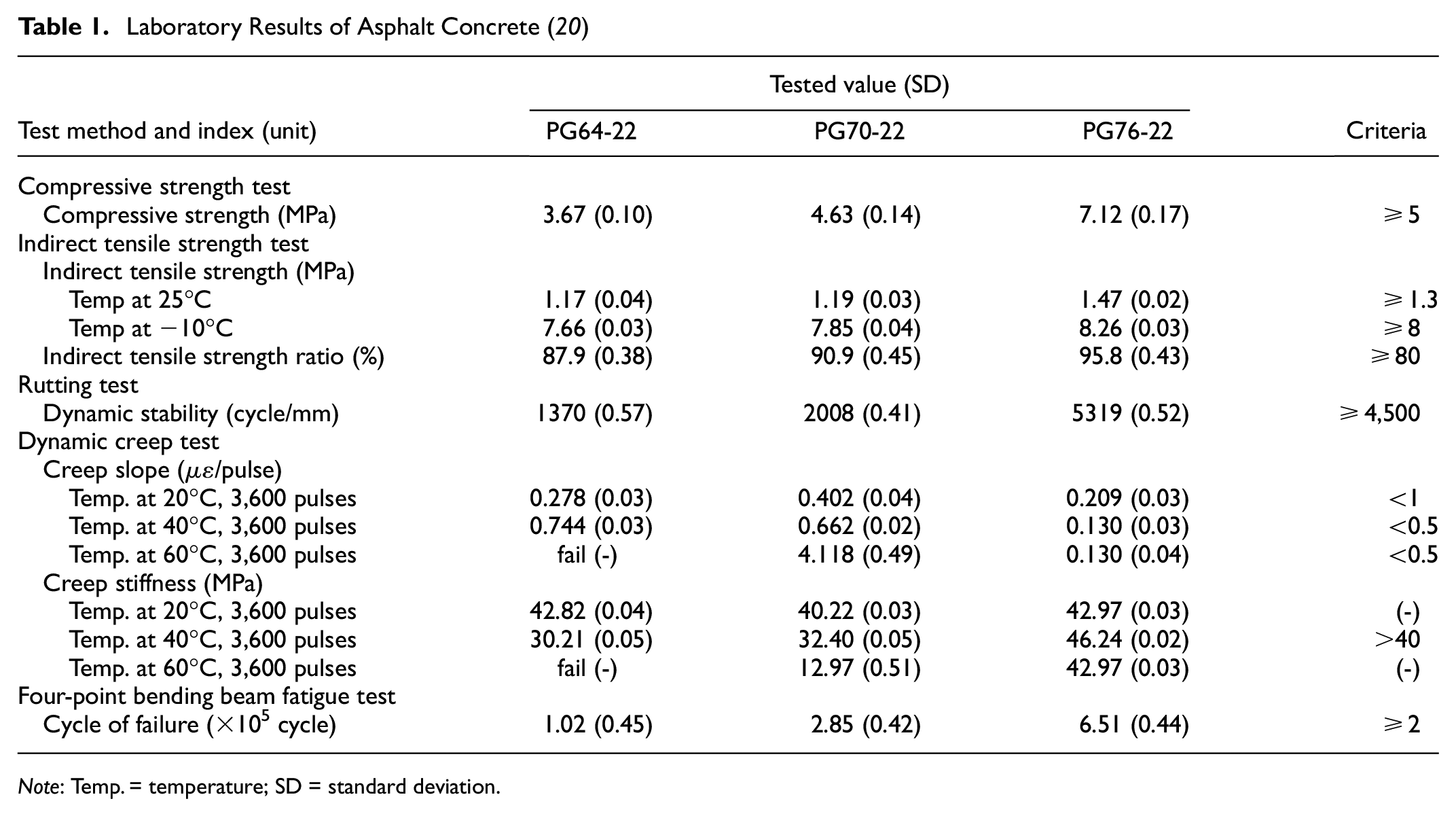
Note: Temp. = temperature; SD = standard deviation.
The laboratory test results shown in Table 1 show that it is feasible for AC to be designed as a waterproof layer (surface course) to support the static and dynamic loads of high-speed trains and withstand the environment under its limited size of aggregate. The PG76-22 or modified grade binder demonstrated responsiveness to both functions and passed all test criteria for use in slab ballastless track. Therefore, PG76-22 is suitable for application in a full cross-section waterproof layer in a high-speed railway ballastless track.
Foam Concrete (FC)
FC is produced by the main components: ordinary Portland cement (OPC), sand, water, and foam agent; in addition, silica, water reducing agent, and PP fiber are added to improve the mechanical properties and bonding of internal structures. OPC type 1 was used throughout the study and met the requirements specified in ASTM C150 ( 29 ). Fine sand was dried in an oven and sieved through a sieve size of 0.6 mm. The foaming agent selected in this study can be used with all types of lightweight aggregates to produce a very low-density concrete mix. The ratio of a foaming agent to water is 0.1 kg:5 kg (1:50) by volume. OPC and water are mixed at a ratio of 0.60 to create the cement paste. Silica fume is added 10% of cement weight and complies with ASTM C1240 ( 30 ). Superplasticizer is a high-range water reducer, used at a ratio of 10 mL per 1 kg of cement weight. PP fiber, a synthetic fiber for reducing early cracking in FC, 12 mm long, 22 micron in diameter, was used throughout this study at 0.25% and 0.40% of the volume of the mix design, which is equivalent to 0.25 kg/m3 and 0.40 kg/m3. The target densities of each mix design were 500, 550, 600, 650, and 700 kg/m3. When the pouring was complete, the specimens were stored for 24 h at a temperature room of 23°C ± 2°C. After that, specimens were demolded for curing in different states for 28 days: they were divided into two parts, one of which was dried in air and the other was immersed in water.
The main purpose of using FC for filling in the subgrade bed of high-speed railway ballastless track is to prevent the risk of soil saturation and to reduce the weight of the material in the structure, which is one of the factors in reducing railway settlement. Therefore, the main function of FC in high-speed railway ballastless tracks for filling into the subgrade bed is load-bearing capacity, cracking resistance, and vibration absorption. To meet the requirements for high-speed railway applications, the laboratory tests consist of compressive strength test in accordance with the procedure in ASTM C39, modulus of elasticity and Poisson’s ratio test according to ASTM C469, splitting tensile strength test in accordance with ASTM C496, and dynamic triaxial test in accordance with ASTM D5311, as shown in Figure 2, a to d , respectively ( 31 , 34 ). The results of the average values of the five FC samples with different target densities and curing states are listed in Table 2.

Laboratory test of foam concrete: (a) compressive strength test, (b) modulus of elasticity and Poisson’s ratio test, (c) splitting tensile strength test, and (d) dynamic triaxial test.
Laboratory Results of Foam Concrete ( 15 )

Note: SD = standard deviation.
The laboratory test results shown in Table 2 show that FC with a density of 500–700 kg/m3 meets the requirements of the high-speed railway subgrade and can be applied as a subgrade material in high-speed railway ballastless track structures. However, the use of FC with a density of 500–550 kg/m3 still poses a risk because of the influence of water, which means that different curing states can cause the concrete strength to drop and fluctuate greatly. In addition to the 0.25% and 0.40% PP fiber additions in FC at each target density, it was shown that the 0.25% fiber addition resulted in a better improvement in mechanical properties than the 0.40% fiber addition. Therefore, the use of FC with a density of 600 kg/m3 and above with a PP fiber content of 0.25% is a better choice for application as a subgrade material in a high-speed ballastless track.
Numerical Model
The dynamic response of AC and FC, when used simultaneously as a full cross-section layer in the CRTS III slab ballastless track, was evaluated through the finite element model by the ANSYS program. Additionally, a comparison of the dynamic response of the whole track structures with and without AC and FC was also assessed to ensure that the track structures with AC and FC had a good ability to resist dynamic loading and settlement of the railway tracks. Also compared were the simultaneous use of AC and FC with the use of either AC or FC in the CRTS III slab ballastless track structures based on the authors’ previous studies.
Train Load and Wheel-Rail Contact Area
In this model, each line of rail was subjected to a set of wheel loading from a single bogie of the CRH380 high-speed train at 350 km/h. The oval area of the wheel-rail contact zone was simplified as a rectangular area in the load modeling through the finite element method, as shown in Figure 3. It is used to reduce the effect on the vertical behavior of high-speed trains from the superposition of static wheel loads and dynamic loads in the form of multiple sinusoidal functions. The wheel-rail contact between the vehicle and track are coupled through a nonlinear Hertz contact model. The train load can be expressed as:

where
and:

where
α i = the vector height of the vibration wavelength, and
ω i = the circular frequency of the vibration wavelength,
and:

where

Finite element model of China Railway Track System III (CRTS III) slab ballastless track structure: (a) track structure with asphalt concrete and foam concrete and (b) wheel load force transmission area.
Based on Equation (1),
Geometry and Boundary Condition
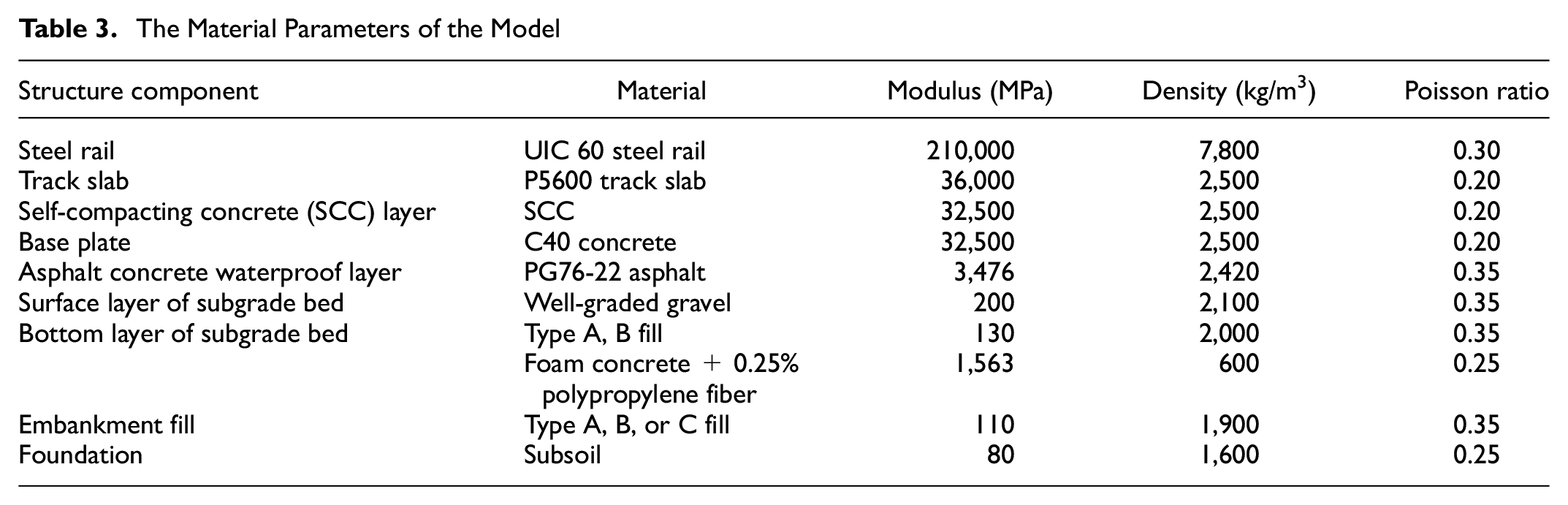
The geometry and material parameters of the CRTS III slab ballastless track structure model were obtained from the China Code for Design of High-Speed Railway in China, TB10621, and are listed in Table 3 ( 36 ). In this study, the track model was 15 m in length. The standard CRTS III slab ballastless track structure consists of steel rail, fastener, track slab, self-compacting concrete (SCC), base plate, the surface layer of subgrade bed, the bottom layer of subgrade bed, embankment fill, and foundation. The UIC 60 steel rail with a standard gauge of 1.435 m and the WJ-8B fastening system with the spring stiffness and damping coefficient of 30 kN/mm and 60 k.s/m were modeled by the SOLID45 and COMBIN14, respectively. The CRTS III P5600 track slab is 5.6 m in length, 2.5 m in width, and 0.2 m in thickness and was modeled by SOLID185. The SCC has the same length and width as a track slab and is 0.1 m in thickness. The length, width, and thickness of the base plate are 16.99 m, 3.1 m, and 0.3 m, respectively. The other layered structures were modeled by element SOLID185 and the deformation of the structures is assumed to be continuous in the multilayer structure under the track slabs. The boundary conditions of the bottom of the foundation layer are constrained to displacement and deformation in all three directions, while the longitudinal end is constrained in rotational and vertical deformation. In this model—the standard of CRTS III slab ballastless track—the thickness of the surface layer of subgrade bed, the bottom layer of subgrade bed, embankment fill, and foundations are 0.4 m, 2.3 m, 0.6 m, and 3.0 m, respectively. The gradient of the subgrade slope is 1:1.5. For structures with AC, the thickness of the surface layer of subgrade bed is 0.28 m. It is recommended to partially replace the traditional surface layer of the subgrade bed with AC at a thickness of 0.12 m. In contrast, FC at thicknesses of 0.5 m, 1.0 m, and 1.5 m, respectively, were recommended to replace all traditional subgrade in the bottom layer of the subgrade bed of the CRTS III slab ballastless track. The whole railway structure with and without a full cross-section of AC and FC is shown in Figure 4.
The Material Parameters of the Model

Layout with and without full cross-section of asphalt concrete and foam concrete on the top and bottom surface layer of subgrade bed of the China Railway Track System III (CRTS III) slab ballastless track structure.
Results and Discussion
Numerical Results
This section assesses the dynamic response when AC and FC are used simultaneously as full cross-section layers in the CRTSIII slab ballastless track structure. In this model, asphalt PG76-22 is designed as a waterproofing layer with a thickness of 0.12 m which is used as part of the top surface layer of subgrade bed, while FC at a density of 600 kg/m3 with 0.25% PP fiber is used as subgrade material in the bottom layer of subgrade bed. The optimum thickness of FC is found by applying FC at thicknesses of 0.5 m, 1.0 m, and 1.5 m, respectively. We also compared the dynamic response of the simultaneous application of AC and FC with the use of either AC or FC from previous studies by the authors. The dynamic response assessment of the track structure with and without AC and FC consists of vertical stress, vertical displacement, and vertical acceleration at the bottom of each layer of the structure, as shown in Figure 5.

The effects of asphalt concrete waterproof layer and foam concrete layer on dynamic responses of the China Railway Track System III (CRTS III) slab ballastless track system: (a) vertical stress of track system, (b) vertical displacement of track system, and (c) vertical acceleration of track system.
The dynamic response comparison in each layer of the CRTSIII slab ballastless track structure with and without AC and FC is shown in Figure 5. The vertical stresses of the whole track structure are shown in Figure 5a. When an AC layer of 0.12 m thickness and FC layers of 1.0 m and 1.5 m thickness are applied, the average vertical stresses of the track structure are reduced by approximately 1.05 and 1.10 times, respectively. In contrast, the use of an AC layer of 0.12 m thickness and a FC layer of 0.5 m thickness increased the vertical stress by approximately 0.77 times that of traditional track structures. As shown in Figure 5b, the average vertical displacement of the whole track structure with an AC layer of 0.12 m thickness and FC layers of 1.0 m and 1.5 m thickness is decreased by 1.44 and 1.86 times from traditional track structures, respectively, while using an AC layer with a thickness of 0.12 m and a layer of FC with a thickness of 1.0 m causes the vertical displacement to increase to 0.86 times from the traditional track structure. For the vertical acceleration of a track structure with AC and FC layers, as shown in Figure 5c. The average vertical acceleration of the whole track structure with AC at 0.12 m thickness and FCs at 1.0 m and 1.5 m thickness decreases by approximately 1.30 and 2.23 times, respectively. However, using AC at 0.12 m thickness and FC at 0.5 m thickness, the vertical acceleration was increased to 0.72 times of that of the traditional track structures.
When analyzing the dynamic response of whole track structures with AC and FC being applied simultaneously compared with traditional track structures, it was found that the optimum thickness for filling FC in the subgrade bed of the CRTSIII slab ballastless track structure is 1.0 m or more, as it can reduce load, settlement, and acceleration better than traditional track structures. In addition, when considering the use of AC for the top surface layer of subgrade bed, it was found that the weight load of this part of the structure increased by about 4% from the traditional track structure. However, using FC with a density of 600 kg/m3 and a thickness of 1.0 m to fill in the subgrade layer can reduce the additional stress on the ground caused by the weight loads by 8.6 times. In conclusion, for the simultaneous use of AC and FC in this study, the overall weight load of the structure was reduced by 5.3 times from the traditional weight load of the track structure. It can indicate that the structure has good long-term stability.
For a comparison of the dynamic response of the simultaneous application of AC and FC with the application of either AC or FC from the authors’ previous studies, see Figure 6 ( 15 , 20 ).

The layout of the China Railway Track System III (CRTS III) slab ballastless track structures with three application of asphalt concrete and foam concrete.
The results of the vertical stress comparison of the three applications of AC and FC are shown in Figure 7a. It has been shown that the simultaneous use of AC and FC can reduce vertical stresses by approximately 1.01 and 1.03 times better than choosing either AC or FC, respectively. As shown in Figure 7b, the vertical displacement of track structures when AC and FC are used simultaneously are approximately 1.32 and 1.03 times lower than track structures with either AC or FC, respectively. The vertical acceleration of the track structure of the three applications of AC and FC is shown in Figure 7c; when AC and FC are used simultaneously, the vertical acceleration can be reduced better than that of the track structure with either AC or FC by about 1.12 and 1.18 times, respectively.

Dynamic response comparison of the China Railway Track System III (CRTS III) slab ballastless track structures from three application of asphalt concrete and foam concrete: (a) vertical stress of track system, (b) vertical displacement of track system, and (c) vertical acceleration of track system.
In addition, the effect of improving the dynamic response by simultaneous application of AC and FC is better than choosing either AC or FC in the model. It can be said that adding a medium modulus layer or asphalt waterproof layer with flexibility, low voids, and fatigue resistance when it is laid between the base plate and the surface layer of the subgrade bed can make the load distribution more uniform, which results in reducing the settlement while the trackbed is on loading, but the weight issue of AC material may increase the pressure on the foundation which affects long-term overall structural settlement. FC has outstanding properties of shock absorption and lightweightness. When it is used in place of traditional materials, vibration and pressure on the foundation of the structure are reduced as the train passes, resulting in the dynamic stability of the track. According to the model results, when the two materials with different outstanding properties are used in the railway structure, the two materials may enhance each other and eliminate the disadvantages of traditional railways. Therefore, it can be concluded that the simultaneous application of AC and FC is better than choosing either AC or FC. In addition, the model cannot clearly indicate the long-term deformation and damage characteristics when the two materials are simultaneously used in railway structures, so future research is needed to study them in large-scale models.
Model Validation
For the model verification, reference to the Zhengzhou-Suzhou high-speed railway in China, where the dynamic characteristics of the top surface of the subgrade bed of the CRTS III slab ballastless track below the center line of the baseplate are measured as the train passes at a speed of 350 km/h. The measurement results show that the dynamic stress ranged from 13 kPa to 24 kPa, the vertical displacement was between 0.01 mm and 0.50 mm, and the vibration acceleration was between 1.6 m/s2 and 3.2 m/s2 as shown in Figure 8 ( 37 – 40 ).

Dynamic response of Zhengzhou-Suzhou high-speed railway: (a) vertical acceleration and (b) vertical displacement.
The dynamic response results of the traditional CRTS III slab ballastless track model in this study showing the maximum vertical stress, displacement, and vibration acceleration on the surface of the subgrade bed of the track structure are 22.95 kPa, 0.39 mm, and 1.86 m/s2, respectively, indicating that the obtained data is reliable.
Conclusions
This paper presents the simultaneous use of AC and FC as full cross-section layers in the CRTS III slab ballastless track structure. The AC is designed as a waterproof layer (surface course) for use in the top surface layer of the subgrade bed in which the mixture is produced by PG76-22 binder. FC is designed as a subgrade material to fill in the bottom layer of the subgrade bed with a target density of 600 kg/m3 and improved with PP fibers at 0.25%. The properties of AC and FC for high-speed railway ballastless track applications were assessed through laboratory testing based on previous studies by the authors. The dynamic response in each layer of the high-speed railway structure when using both materials simultaneously was assessed through numerical modeling. We also compared the dynamic response between the simultaneous use of AC and FC with the use of either AC or FC. The results of this research are summarized as follows:
The numerical models show that the use of AC thickness of 0.12 m and FC thickness of 1.00 m in high-speed railway can reduce dynamic response more than traditional track structures. In addition, with the simultaneous use of AC and FC, the overall weight of the material structure was reduced by 5.3 times from the traditional weight of the structure. This can indicate that the track structure has good long-term stability.
The numerical model shows the three applications of AC and FC. It has been found that the simultaneous use of AC and FC can reduce the dynamic response and weight of the railway structures caused by the material better than using either AC or FC. In addition, the use of AC as a single material results in an increase in the weight of the track structure from the traditional track structure. Therefore, the simultaneous use of AC and FC, or the use of FC as a single material, results in a good reduction in the weight of the track structure, which means the additional forces acting on the foundation are also reduced.
Footnotes
Acknowledgements
The authors would like to thank Tipco Asphalt PCL, Thai-German Institute, and King Mongkut’s Institute of Technology Ladkrabang, Thailand, for technical advice and facilitating laboratory testing.
Author Contributions
The authors confirm contribution to the paper as follows: study conception and design: T. Klomranok, Q. Su; data collection: T. Klomranok; analysis and interpretation of results: T. Klomranok, Q. Su; draft manuscript preparation: T. Klomranok. All authors reviewed the results and approved the final version of the manuscript.
Declaration of Conflicting Interests
The author(s) declared no potential conflicts of interest with respect to the research, authorship, and/or publication of this article.
Funding
The author(s) disclosed receipt of the following financial support for the research, authorship, and/or publication of this article: This research was funded by the Chinese Scholarship Council under grant number 2016GXY779.