



Abstract
The shear strength of geocell-reinforced railway roadbeds is influenced by diverse factors. This research aimed to explore the shear deformation performance of the geocell-reinforced railway roadbed under conditions of different reinforcement locations, confining pressures, and numbers of reinforced layers. To this end, large-scale undrained triaxial tests were conducted to measure the mechanical properties of a geocell-reinforced railway roadbed. The results show that geocell reinforcement plays a significant role in improving the peak deviatoric stress of the railway roadbed. The stress–strain relationship of the railway roadbed always exhibits strain-hardening characteristics, and the railway roadbed shows the optimal shear deformation resistance and strength when it is reinforced in its upper part. As the confining pressure increases, the shear strength and stiffness of the railway roadbed both increase while the secant modulus decreases with increasing axial strain. Meanwhile, the shear strength and strength coefficient of reinforcement of the railway roadbed both increase significantly with the increasing number of reinforced layers, along with large increases in the stiffness and energy absorption of the railway roadbed. The research results can provide a reference for the structural design of railway ballast layers to comprehensively control the stability and deformation of existing heavy railway roadbeds.
The settlement (both total and differential) of railway roadbeds affects the comfort and safety of trains in service. Ensuring the smoothness and safety of trains in service and controlling railway roadbed deformation are important aspects in the design of railways ( 1 ). In the operational life of railway tracks, the lateral displacement of filling materials comprising railway roadbeds may cause accumulation of vertical settlement and breakage of the aggregate, eventually altering the track geometry. In addition, track profiles and railway lines are significantly affected by the deterioration and settlement of aggregates used as fill ( 2 ). The insufficient lateral confinement of the railway roadbed is the main cause of the deformation and failure of tracks. Such over-deformation and failure of tracks will inevitably increase with the increasing velocity and axle load of trains ( 3 , 4 ).
Geocells are widely used geosynthetic materials; in particular, they are used to improve the bearing capacity of subgrades, embankments, railways, and heavy traffic areas ( 5 – 10 ). Some research into geocell-reinforced ballasted railway roadbeds has shown that geocell reinforcement is conducive to the long-term stability of ballasted railway tracks ( 10 – 14 ). Geocell reinforcement helps reduce the transverse and vertical deformation of the track layer and therefore maintains the geometric shape of the tracks ( 15 , 16 ). Geocells increase the stiffness of filling materials, which contributes to a more uniform distribution of traffic-induced stress on subgrades and does so across a wider range ( 17 – 19 ). It also lowers or redistributes the shear stress at the ballast–sub-ballast or the sub-ballast–subgrade interface, depending on the location(s) of the reinforcing materials ( 20 ).
In recent years, various scholars have conducted model tests on, and numerical simulations of, the behavior and performance of geocells in many scenarios. With respect to model tests, Zhou and Wen ( 19 ) and Suku et al. ( 21 ) used geocells to reinforce sand cushions and embankments. They revealed that the reaction coefficient K30 increases by 3000% while the settlement deformation is decreased by 44% for soft subgrades in geocell-reinforced weak railway roadbeds. Pokharel et al. ( 22 ) conducted tests involving reinforcement of the subgrade using different numbers of geocells under cyclic loading and found that, compared with a single geocell, reinforcement with multiple geocells further decreases the permanent subgrade deformation. Fattah et al. ( 23 , 24 ) conducted a series of tests adopting geogrids to reinforce the ballast and clay layers separately. They concluded that geogrid reinforcement of the ballast layer is more effective. Meanwhile, the settlement of the ballast layer decreases with the increasing number of geogrids ( 22 ). Lackenby et al. ( 25 ) performed triaxial tests on railway ballast under different confining pressures. Analysis of the tests shows that enlargement of the lateral confining pressure on the ballast can decrease the settlement of the track, thus increasing its stability and stiffness. Indraratna et al. ( 26 ) conducted true triaxial tests by reinforcing railway sub-ballast using geocells and concluded that the additional confining pressure generated by geocell reinforcement lowers the vertical strain and volumetric strain of the sub-ballast. In addition, compared with unreinforced (UR) sub-ballast, the settlement also reduces by about 12%–25%. With respect to numerical simulation, Indraratna et al. ( 27 ) adopted the discrete element method (DEM) to simulate direct shear tests on ballasted tracks reinforced with geogrids. Analysis indicates the strain-softening behaviors and volume expansion phenomena of the ballast. As the normal stress is increased, the shear strength increases and the volumetric expansion decreases. Leshchinsky and Ling ( 28 ) simulated and investigated a geocell-reinforced railway embankment through finite element analysis (FEA) parametric modeling. They found that geocell reinforcement enhances the stiffness and strength of the gravel embankment and reduces the vertical settlement and lateral displacement thereof. Leshchinsky and Ling ( 29 ) modeled blocky particles using the DEM to simulate a geocell-reinforced ballast embankment. Their research proved that, compared with the UR case, the vertical displacement and lateral deformation of geocell-reinforced ballast embankment both decrease. Some researchers also studied the performance of a geocell-reinforced railway roadbed at different locations of the track, such as the ballast, sub-ballast, or soil subgrade. The research results demonstrate that the ideal location for geocell reinforcement is in the railway roadbed just beneath the sleepers ( 26 , 30 , 31 ).
Most current research on geocells focuses on simple structures, including scaled-down model tests, single ballast layers, or sub-ballast layers. However, limited studies have investigated the impact of complex environmental conditions on the reinforcement performance of geocells in railway roadbed structures, particularly with regards to the location, number of reinforcement layers, and additional restraining force. Since the reinforcement mechanism of geocells needs to be investigated based on the reinforcement effect of the whole roadbed layer structure, it is imperative to conduct a large-scale triaxial test of the railway roadbed layer structure, examining the impact of reinforcement location, quantity, and confining pressure on the reinforcement effect of the railway roadbed layer. This paper takes the geocell-reinforced railway ballast layer as the research object. Large-scale static triaxial tests were conducted to examine the mechanical properties of the geocell-reinforced railway roadbed layer under diverse reinforcement positions, the number of reinforcement layers, and confining conditions. The study discusses the effects of optimal geocell reinforcing positions and varying numbers of reinforcements on the strength and deformation characteristics of the railway roadbed.
Materials and Tests
Test Equipment
A DJSZ-150 large-scale static-dynamic triaxial test instrument for coarse-grained soil was adopted, as shown in Figure 1. The instrument comprised a computer host, an automatic excitation system for dynamic axial pressure, a stabilization system for static axial pressure, a pressure chamber, a confining-pressure stabilization and control system, an automatic data acquisition system, and a cooler. The maximum axial dynamic load, maximum confining pressure, and loading frequency of the equipment were respectively 200 kN, 3.0 MPa, and 0.01–5 Hz, and it could hold a sample measuring 300 mm × 600 mm.

DJSZ-150 large dynamic and static triaxial instrument.
Test Purpose and Materials
The heaviest train axle load permissible on the North Tongpu Line’s heavy-duty railway in China is 27 t, while the maximum operating speed is 85 km/h. Based on the design standards of the Code for designing heavy haul railway (TB10625—2017) ( 32 ), experimental research was conducted to simulate the scenario where the axle load will increase to 30 t after the expansion and renovation of China’s heavy-duty railways.
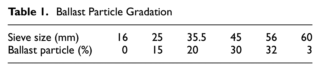
The railway ballast used in the tests was graded crushed rocks for railway roadbeds taken from the quarrying site used for railway construction, the parent rock of which was a granite. By referring to the Code for designing heavy haul railway (TB10625—2017) ( 32 ), ballast and sub-ballast materials were separately screened and prepared to simulate gradation curves of aggregates in real railway roadbeds (Figure 2 and Tables 1 and 2). By conducting heavy compaction tests, the maximum dry densities and optimal moisture contents of ballast and sub-ballast materials were ascertained: key physical parameters used in the tests are listed in Table 3.
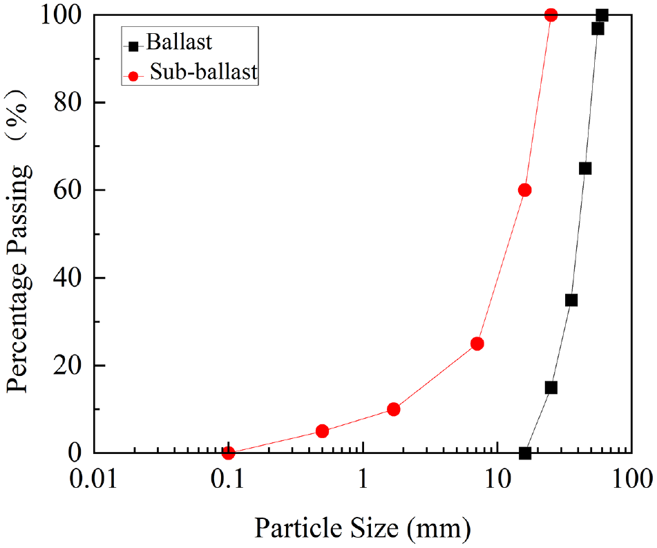
Test ballast and sub-ballast grain size gradation curves.
Ballast Particle Gradation
Sub-Ballast Particle Gradation

Physical Properties of Ballast and Sub-Ballast

The TGLG-100-400 honeycomb geocells were used as reinforcing materials in the large-scale triaxial tests, as shown in Figure 3. Geocells are three-dimensional (3D) honeycomb structures used for soil reinforcement and erosion control. Made from high-density polyethylene (HDPE) material, they are 3D structures consisting of interconnected grids that form a series of honeycomb cells. These honeycomb cells can be filled with soil, gravel, concrete, or other fill materials. Various physical and mechanical indices of the honeycomb geocells are listed in Table 4.
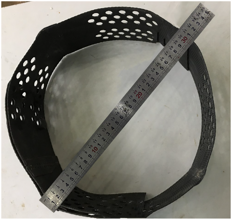
Reinforcing materials in the tests.
Technical Parameters and Indices of Geocells

Note: HDPE = high-density polyethylene.
Sample Preparation
The test samples had a diameter of 300 mm, a height of 600 mm, and a height-to-width (H/D) ratio of 2. The filler used in the ballast and sub-ballast layers was coarse granite stone with a particle size of 25–60 mm and granite stone with 0.1–25 mm fine particles, respectively. Coarse-grained ballast and fine-grained sub-ballast were prepared by using two different fillers in accordance with the “Code for Design of Heavy-Duty Railways” (TB10625-2017; TB 10102-2010). As demonstrated in Tables 1 and 2, the specimens are 12 times the diameter of the largest particle size of the graded gravel in the sub-ballast layer and five times the diameter of the largest particle size of the graded gravel in the ballast layer, which could eliminate the influence of the size effect ( 33 ). The sample preparation process is illustrated in Figure 4. To simulate actual conditions of the filler layer of graded crushed rocks under an invariant moisture content of filling materials of the railway roadbed, samples were prepared according to the compaction requirement for the filling materials of graded crushed rocks for the roadbed of actual heavy haul railways. The compaction coefficient was set to be 0.95. Layered compaction method: the volume weights of corresponding filling materials in six heights (each of which was 100 mm) were calculated in the preparation process. The prepared filler is removed and poured into the sample mold, and the surface is levelled and compacted 25 times. After each layer of compaction, the filler is approximately 1/6th of the volume of the sample mold. The compaction hammer should fall freely during the process, and its trace on the filler’s surface should be evenly distributed. Repeat these steps to compact the second to sixth layers. Sample preparation procedures were performed according to the Design Specification for Heavy-Duty Railway (TB10625-2017) and the Standard for Geotechnical Test Methods (GB/T50123-2019).
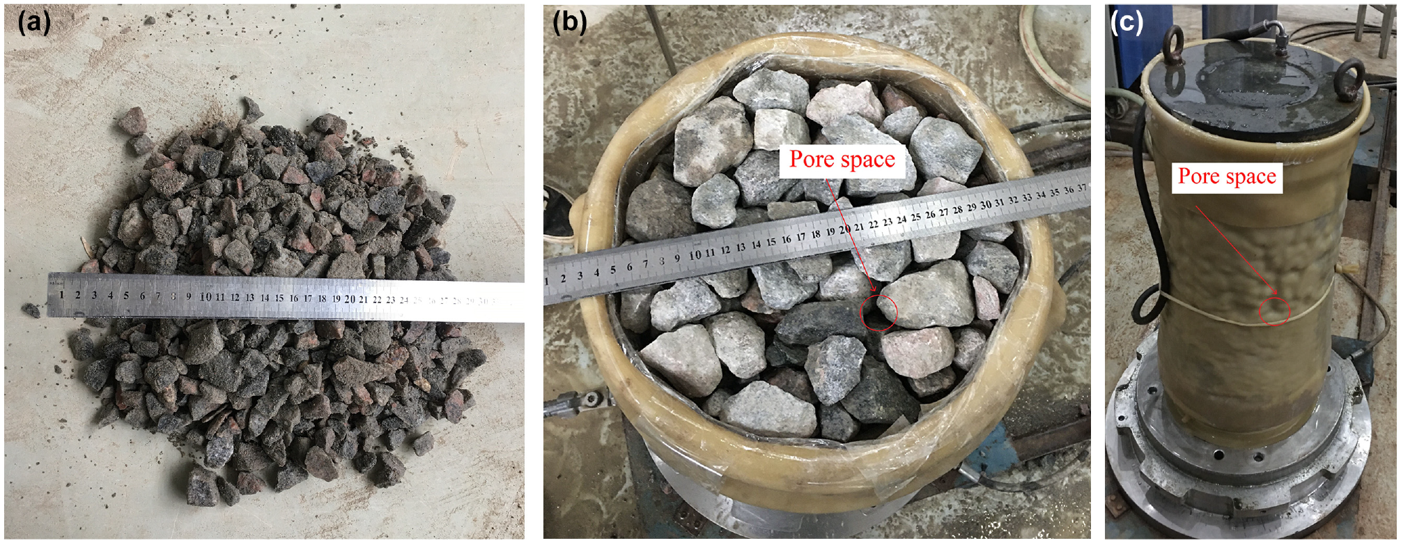
Sample preparation process: (a) material mixing, (b) sample compaction, and (c) vacuumization and preparation of samples.
The compacted ballast and sub-ballast layers both had a thickness of 300 mm, matching the depths of the ballast and sub-ballast layers below sleepers on the railway site. For geocell-reinforced ballast samples, the upper geocell (GS1) reinforcement refers to placing geocells at the ballast–sub-ballast interface and a location 100 mm from the interface (Figure 5b). The locations of geocells in the ballast layer in the current research match those in the research of Sadeghi et al. ( 34 ), both lying beyond the tamped area, are displayed in Figure 5.

Geocells reinforcement layout: (a) unreinforced (UR) geocells, (b) reinforced upper part of geocells (GS1), (c) reinforced in the middle of geocells (GS2), (d) reinforced bottom of geocells (GS3), and (e) reinforced entire geocells (GS4).
Test Process
After compacting the samples, a sample cap was placed on the top of each sample. Then, a pipe for measuring volume change, a saturated inlet pipe, a pipe for providing pore-water pressure, and a vacuum pipe were connected to loading caps on the base and top of the instrument. Afterwards, the sample was maintained in its vertical position by application of a vacuum. The sample preparation process is shown in Figure 4.
To prevent the latex film from being punctured, a polyvinyl chloride (PVC) film was tightly stuck to the inner side of the latex film in the tests. The thickness of the PVC film should not exceed 1% of the sample diameter and it was about 2 mm in the present research. The honeycomb geocells were placed inside the samples and tightly adhered to the PVC film. The reinforcement layouts are shown in Figure 5.
The vacuum was removed when the negative pore-water pressure reached 70–80 kPa, followed by installation of the pressure chamber and flushing. Then, the pore-water pressure was released and confining pressure of 40 kPa was applied at the same time to avoid collapse of the sample. Two saturation modes were adopted for the sample, namely, vacuum saturation and head saturation. By applying the confining pressure, the ratio of the increment of confining pressure to that of pore-water pressure was calculated. Skempton’s pore-pressure coefficient B was measured, and the saturation was controlled to be higher than 95%. The consolidation was stopped when the water discharge in the process remained stable.
Reinforcement Mechanism of Reinforced Soil
Reinforced soil is a macroscopic composite: the reinforcement mechanism thereof can be explained by the principle of equivalent confining pressure or that of quasi-cohesion ( 35 ). The principle is described as follows: under external load, geocells are subject to friction and intercalation with soil, generating deformation and tensile stress in the reinforcement. Such tension confines the lateral deformation and improves the shear strength of soil (Figure 6).
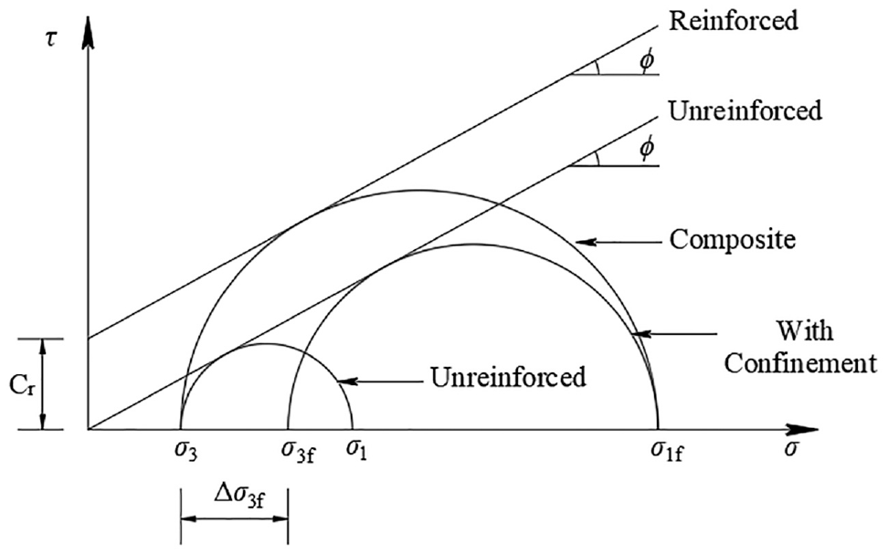
Mohr circles for calculations of apparent cohesion for the geocell–soil composite ( 40 ).
For the principle of equivalent confining pressure (
36
–
38
), in triaxial tests, the improvement of tensile strength of reinforced soil can be regarded as increasing the confining pressure around the UR soil. The reinforcement is equivalent to providing a lateral confining pressure





where
For the quasi-cohesion principle ( 39 ): according to the Mohr–Coulomb failure criterion, the mathematical expression of samples in the new equivalent state is as follows:




where
Results and Analysis
After railway roadbed samples were consolidated, consolidated-undrained (CU) shear tests were conducted, during which the shear rate was set to 0.5 mm/min. The axial load and axial deformation of the samples were collected using the computer in the test process and the stress–strain curves were drawn synchronously, until failure or reaching an axial strain of 15% ( 33 ). The test confining pressures were set at 50, 100, and 150 kPa to simulate the actual lateral pressures on the upper and lower surfaces of the surface layer and the lower surface of the subgrade layer of the heavy railway bed in urban and suburban railway environments. The test schemes are summarized in Table 5. At the same time, 30 large-scale triaxial shear tests were conducted on railway roadbed specimens in five states with and without geocell reinforcement under three different values of σ3. The following results were obtained: stress–strain curves, shear strength parameters, stiffness curves, charts for changes in energy absorption with reinforcement locations, and the strength coefficient (SR) of reinforcement under different confining pressures. On this basis, the influences of geocell reinforcement on the shear strength of the railway roadbed were evaluated.
Design Schemes of Static Triaxial Tests

Note: UR = unreinforced.
Influence of Geocell Reinforcement on Stress–Strain Curves of the Railway Roadbed
Static triaxial tests were conducted on railway roadbed samples under confining pressures of 50, 100, and 150 kPa, during which the stress–strain curves were obtained (Figure 7). Under the three different confining pressures, the railway roadbed samples are always strain-hardened regardless of the form of reinforcement. The data in Figure 7 show that as the cumulative axial strain increases, the peak deviatoric stress also increases. When the cumulative axial strain reaches 5%, the rate of change of deviatoric stress decreases. The railway roadbed samples exhibit strain-hardening and dilatancy characteristics in the entire shear process. During loading of the same confining pressure, the effect of GS1 reinforcement is improved compared with GS2 and GS3 reinforcement. Compared with UR samples under three different confining pressures, the peak deviatoric stress of GS1 reinforcement improves by 33.8%, 24.9%, and 23.8%; that of GS2 reinforcement increases by 23.9%, 16.2%, and 26.1%; the peak deviatoric stress of GS3 reinforcement increases by 17.4%, 5.8%, and 15.6%; the peak deviatoric stress of GS4 reinforcement increases by 62.5%, 33.5%, and 44.6%, respectively.
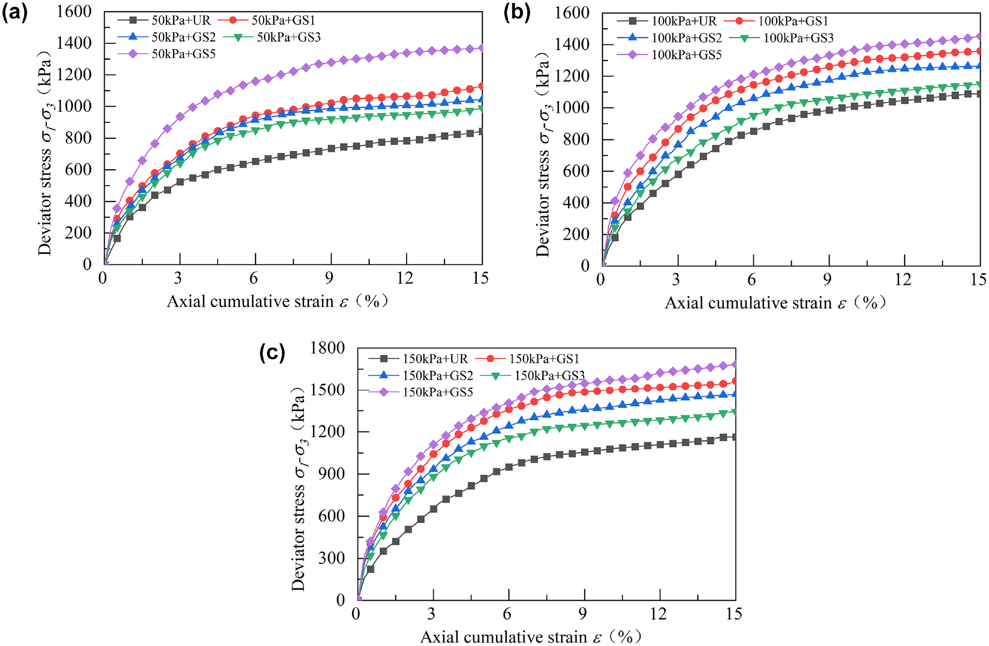
Stress–strain curves for geocell-reinforced track bed layers at three different confining pressures: (a) 50 kPa geocell reinforcement, (b) 100 kPa geocell reinforcement, and (c) 150 kPa geocell reinforcement.
The test results show that in the initial stage of static loading, there are gaps between the skeleton of filling particles in the samples (Figure 4, b and c ). Under static loading, the cumulative axial strain develops rapidly in the early stage because of dislocation and squeezing between ballast aggregates. As loading continues, some aggregates become worn and compacted because of interactions between particles. Broken fine-grained ballast aggregates fill voids in the ballast, so that the contact area between ballast and geocells is increased, thus increasing the frictional resistance to sliding (the increasing vertical load has a similar effect). The confinement provided by 3D elements of the geocells contributes to improving the stiffness and strength of ballast aggregates contained and reducing the cumulative axial strain of ballast. It also avoids lateral motion of filling materials of the railway roadbed, thus reducing geometric deformation of the tracks.
Influence of Different Confining Pressures on Stress–Strain Curves
Figure 8 indicates that under the same reinforcement forms, different confining pressures change the peak deviatoric stress and axial strain of the railway roadbed. With the increase in the confining pressure, the peak deviatoric stress of the railway roadbed sample increases and that of GS4 reinforcement also increases significantly. As the confining pressure varies, compared with the same reinforcement that forms under a confining pressure of 50 kPa, the peak deviatoric stress increases by 20.4% and 38.7% after GS1 reinforcement under 100 and 150 kPa; it increases by 20.9% and 40.4% after GS2 reinforcement; and it increases by 16.2% and 35.8% after GS3 reinforcement, respectively. Under a low confining pressure, GS1 reinforcement plays a favorable role in increasing the peak deviatoric stress; under a high confining pressure, GS2 reinforcement exhibits the optimal increment in peak deviatoric stress.
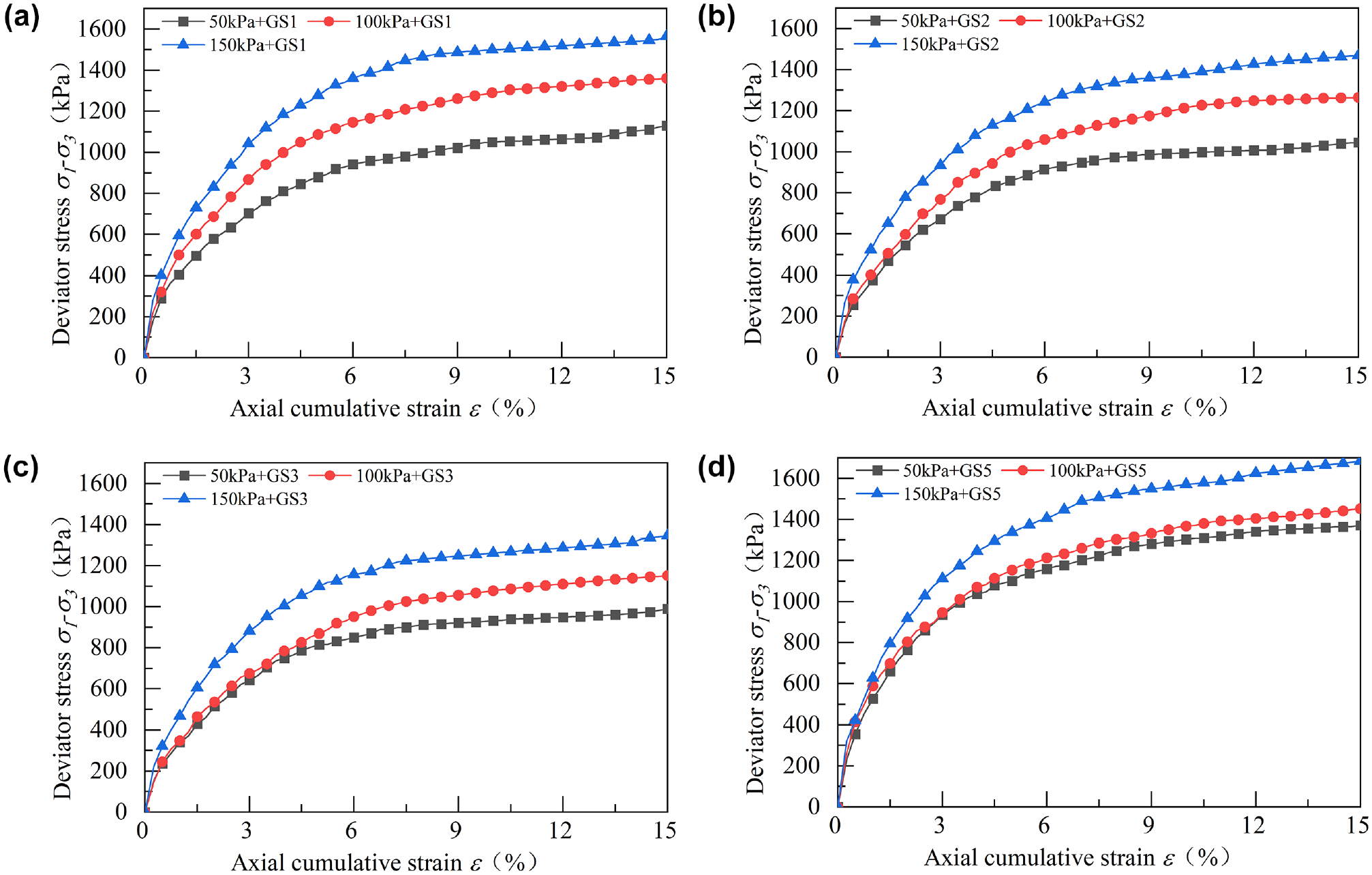
Stress–strain curves of geocell reinforcement under different confining pressures: (a) GS1, (b) GS2, (c) GS3, and (d) GS4.
At the same reinforcement locations, the peak deviatoric stress of the geocell-reinforced railway roadbed also increases with increasing confining pressure. A larger confining pressure is conducive to reducing the lateral and axial strain in the ballast. When constructing railway roadbeds, increasing the confining pressure to a certain extent can change the peak deviatoric stress of railway roadbeds, thus improving their stability and bearing capacity ( 26 ). Therefore, to improve the deformation resistance of railway roadbeds, geocell reinforcement can be applied to railway roadbeds to strengthen the lateral confinement afforded to the roadbeds in railway design ( 10 , 16 ).
Influence of the Number of Reinforced Layers on Strength
The strength of railway roadbed samples was compared under different numbers of geocell-reinforced layers (Table 6). During loading under the same confining pressure, the reinforcement effect of GS4 is improved compared with those of GS1, GS2, and GS3. Compared with UR samples under three different confining pressures, the strength of railway roadbed samples significantly increases when using any of the four forms of reinforcement. Compared with GS4 and GS1, the peak deviatoric stresses under GS4 respectively increases by 21.4%, 6.8%, and 7.5%. GS4 reinforcement shows the best reinforcing effect on the railway roadbed. Test results show that when laying two layers of geocells in the railway roadbed, the peak deviatoric stress at failure can be improved by 16.2%–33.8% under different confining pressures; when laying five layers of geocells, the peak deviatoric stress at failure is improved by 33.5%–62.5%. The peak deviatoric stress at failure under conditions of laying five layers of geocells is much greater than that when laying two layers of geocells. Applying geocell reinforcement to railway roadbed samples improves their strength. When using the same reinforcing material, the larger the number of reinforced layers, the greater the reinforcing effect.
Comparison Among Strengths With Different Reinforced Layers

Based on the design standards of the Code for Designing Heavy Haul Railway (TB10625—2017), it has been demonstrated that for trains with an axle load of less than 23 t, the recommended reinforcement schemes are UR and GS3; for trains with an axle load of 23–27 t, the recommended reinforcement schemes are GS2 and GS3; and for trains with an axle load of 27–30 t, the recommended reinforcement schemes are GS1 and GS4 (Table 7). These findings serve as a crucial point of reference for designing future railway roadbeds. They can support engineers in selecting adequate reinforcement and compression schemes based on the anticipated train axle load, and ensure the long-term stability and durability of railway roadbeds.
Train Axle Loads and Reinforcement Options
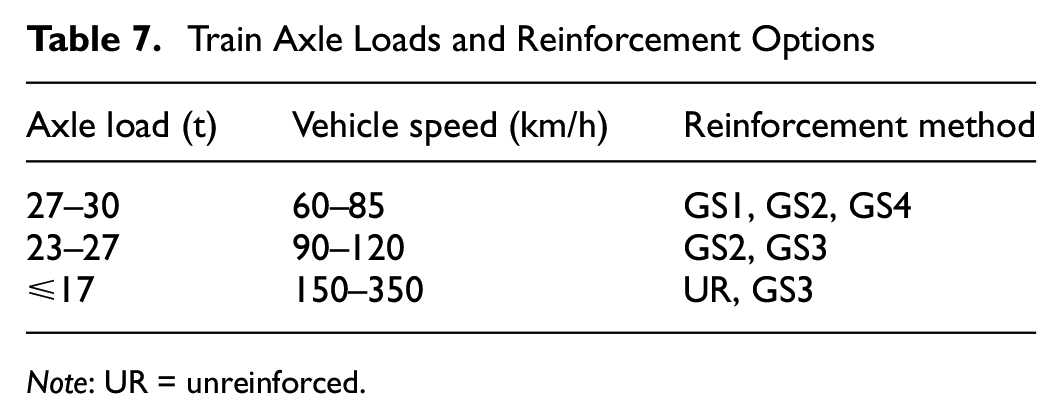
Note: UR = unreinforced.
Axial Plastic Strain Under Cyclic Loading
Based on the results of the static triaxial test, cyclic loading tests were carried out on geocell-reinforced railway roadbed samples. On the heavy-duty railway in North Tongpu, China, the maximum axle load of the railway roadbed is 30 t and the maximum operating speed is 85 km/h. Different train speeds and axle loads result in different dynamic loads on the railway roadbed ( 14 ). The dynamic stress amplitude σd in the tests of this study is 450 kPa ( 14 ), the dynamic loading waveform is sinusoidal, the loading frequency is 3 Hz, and the number of cyclic loading times N is set to 20,000 to simulate the operation of a heavily loaded railway. The test will be stopped automatically when the number of cycles reaches 20,000 or the axial plastic strain of the sample reaches 5% of its initial height ( 33 ).
Figure 9 shows the relationship among axial plastic strain (εp), confining pressure, and number of cycles for different reinforcement methods. The results indicate that εp rapidly increases in the initial cycles and gradually stabilizes after 10,000 cycles. Comparing GS1 with UR material under three different confining pressures, after 20,000 cycles, the εp of GS1 decreases by 42.1%, 49.2%, and 50.1%, respectively; that of GS2 decreases by 36%, 39.7%, and 41.4%; that of GS3 decreases by 17.4%, 28.1%, and 36.4%; and that of GS4 decreases by 52.1%, 57.3%, and 71.2%. Under cyclic loading, the reinforcing effects of geocell reinforcements are in the following order: GS4 > GS1 > GS2 > GS3 > UR.

Curve of axial plastic strain of geocell reinforcement versus number of cycles: (a) 50 kPa geocell reinforcement, (b) 100 kPa geocell reinforcement, and (c) 150 kPa geocell reinforcement.
Geocells are considered a superior 3D reinforcement material. The lateral confinement force and frictional resistance they provide enhance the interlocking effect between particles, leading to an increase in the cohesion and friction angle of the fill material. Under the effect of load, the roadbed filler produces lateral deformation and squeezes the inner wall of the geocell, and the tension force produced after a certain deformation of the geocell reacts on the filler particles, so as to restrain the lateral deformation of the roadbed. Geocell reinforcement can restrict the lateral and vertical development of the roadbed and improve the integrity and continuity of the roadbed.
Comprehensive Evaluation of the Reinforcement Effect
Large-scale triaxial shear tests were conducted on geocells with four different forms of reinforcement. In this way, the shear strength, stiffness, energy absorption capacity, and reinforcement SR of the railway roadbed were evaluated under conditions of different reinforcement locations, confining pressures, and numbers of reinforced layers. Influences of different reinforcement forms on shear deformation performance and deformation resistance of the railway roadbed were evaluated.
Shear Strength Parameters
The shear strength parameters differ significantly for railway roadbed samples reinforced at different locations with geocells (Figure 10). Compared with UR samples, the cohesion and internal frictional angle of railway roadbed samples both tend to increase, which is consistent with the conclusions reached by Mehrjardi et al. ( 41 ) and Zhang et al. ( 42 ). They found that geocell reinforcement enhances the apparent cohesion and internal frictional angle of the filling materials. Under GS1 reinforcement of the railway roadbed, the cohesion and internal frictional angle increase compared with those under GS2 and GS3 reinforcement: because sharp corners of coarse-grained ballast aggregates generate friction with the geocell walls and the broken and fractured sharp corners fill in gaps between aggregates, the contact area between aggregates increases. In addition, the cohesion and internal frictional angle between aggregates also increase. When geocells are used to reinforce railway roadbed samples, the internal frictional angle affects the shear strength of coarse-grained filling materials while only slightly influencing that of fine-grained materials. In GS4 reinforcement, the cohesion and internal frictional angle both reach their maxima and the shear strength of the railway roadbed is superior to that when using other forms of reinforcement. This also proves that, with the increasing number of geocell-reinforced layers, the shear strength of railway roadbed samples is also improved significantly.
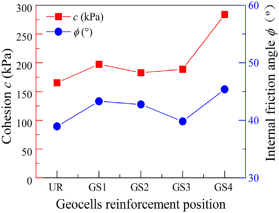
Shear strength parameters of geocell reinforcement at different positions.
Changes in Stiffness
The secant elastic modulus E is commonly adopted to describe the stiffness of soil in static triaxial tests. Here, E is defined as the slope of the straight line connecting a point on the (σ1−σ3)−ε curve with the origin. Previous research into the mechanical properties of railway roadbed materials focuses on the strength and deformation thereof: their stiffness is rarely studied.
As shown in Figure 11, the secant elastic modulus gradually decreases with the increase in axial strain, that is, railway roadbed samples are work-softened. In addition, the secant elastic modulus E attenuates rapidly in the initial stage of loading. However, with the continuous increase in the axial strain, the curve flattens and attenuation diminishes. The figure also indicates that with the growing confining pressure and number of reinforced layers, the stiffness of the railway roadbed with the same axial strain increases. Figure 11 show that, compared with UR samples, the stiffness of the railway roadbed always increases significantly at different reinforcement locations (corresponding to the four different forms of reinforcement). This is because the load borne by the materials used to fill the railway roadbed is transferred to geocells as a circumferential stress, thus stiffening the entire railway roadbed. As the circumferential stress on the geocells increases, the stiffness of the filling materials used in the railway roadbed also rises and correspondingly the lateral deformation of the railway roadbed is significantly decreased (Figure 12, a, b) ( 15 , 43 ).
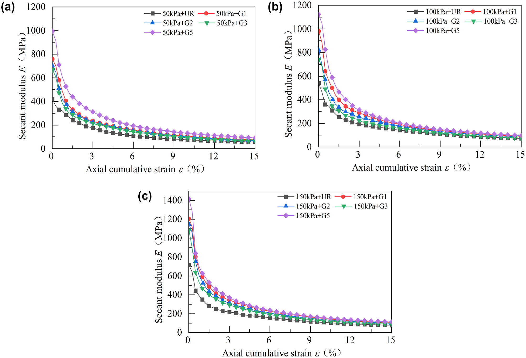
Stiffness–strain curves of geocell reinforcement under different confining pressures: (a) 50 kPa geocell reinforcement, (b) 100 kPa geocell reinforcement, and (c) 150 kPa geocell reinforcement.
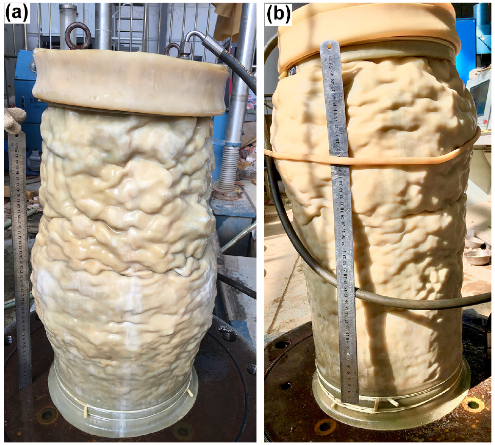
Shear deformation characteristics of GS1 and GS2 reinforced samples: (a) GS1 and (b) GS2.
Figure 13 illustrates the relationship between the dimensionless secant elastic modulus E/E0 and dimensionless deviatoric stress (σ1−σ3)/(σ1−σ3)max, in which E0 and (σ1−σ3)max respectively represent the initial elastic modulus and peak deviatoric stress of soil. With the increase of (σ1−σ3)/(σ1−σ3)max, E/E0 gradually decreases, and the two are linked by a non-linear relationship. The figure also shows that, with increasing confining pressure, (σ1−σ3)/(σ1−σ3)max gradually increases under the same E/E0, and the slope of the curve first increases, then decreases. The dimensionless deviatoric stress tends to a state of linear variation after reaching 0.4. Comparison of Figure 11, a–c, reveals that the stiffness curve shifts upwards as the confining pressure is increased, and the stiffness increases in G4 and G3 when compared with other forms of reinforcement. In addition, the figures also show that for geocell-reinforced railway roadbed samples (Figure 11, a–c), the curve can be divided into two parts: before (σ1−σ3)/(σ1−σ3)max reaches 0.4, E/E0 declines with the increase in (σ1−σ3)/(σ1−σ3)max and the curve is steep; after (σ1−σ3)/(σ1−σ3)max reaches 0.4, (σ1−σ3)/(σ1−σ3)max and E/E0 decrease simultaneously, the curve changes gently, and the two are in an approximate linear relationship.
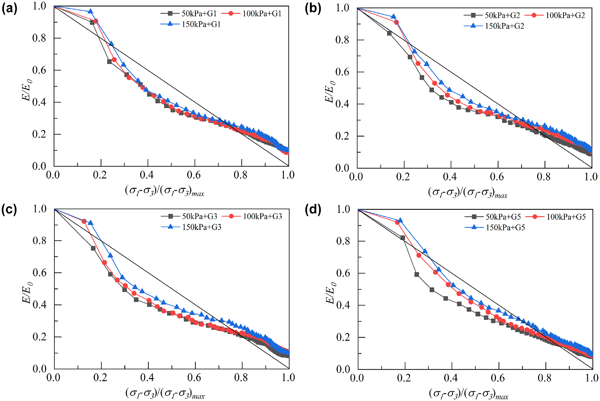
Normalized stiffness–deviator stress curves of geocell reinforcement under different confining pressures: (a) GS1, (b) GS2, (c) GS3, and (d) GS4.
Energy Absorption Capacity
Railway roadbed samples are deformed in the test process. The energy needed for such deformation is called energy absorption. Energy absorption is the energy needed to deform a geocell-reinforced roadbed samples under load ( 44 – 47 ). This study uses the amount of energy required to deform a railway roadbed sample under load to quantitatively analyze how the location, quantity, and confining pressure changes of geocell reinforcement affect the deformability of the railway roadbed samples. The calculation for this is derived from the area below the stress–strain curve depicted in Figure 7. Figure 14 depicts changes in energy absorption under geocell reinforcement in the case of different reinforcement locations, confining pressures, and numbers of reinforced layers.
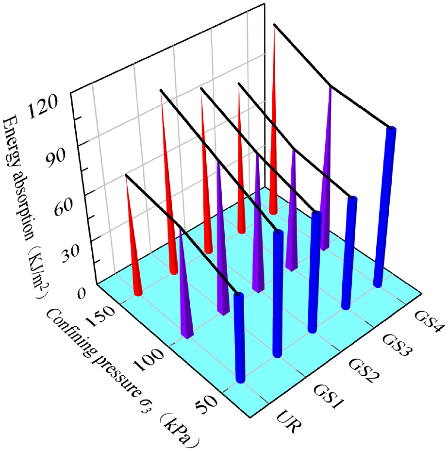
Energy absorption capacity of geocell reinforcement.
Under the same axial strain, energy absorption for deformation of the geocell-reinforced railway roadbed is larger. This conforms to the results of Consoli et al. ( 47 ), who reported that when in fiber reinforcement, the energy absorption potential of soil is enhanced. The difference in energy absorption of the railway roadbed in GS1 reinforcement under conditions of different confining pressures and reinforcement locations is more significant compared with those in GS2 and GS3. Compared with other forms of reinforcement, energy absorption increases more significantly in GS4 with the growing number of reinforced layers. The enhanced energy absorption potential is significantly correlated with sliding friction between aggregates and geocells, increased peak strength caused by confining pressure, and improved peak responses because of the number of geocell-reinforced layers. The presence of geocells, on the one hand, provides additional confinement, which increases the stiffness of railway roadbed samples and therefore enhances the deformation resistance; on the other hand, the comprehensive effect of geocell reinforcement enlarges the area under the stress–strain curve and therefore increases the energy absorption. Therefore, the interactions of the reinforcement location, confining pressure, and number of reinforced layers with energy absorption prove that the effects of geocell reinforcement locations on energy absorption increase with the confining pressure and number of reinforced layers.
Strength Coefficient of Geocell Reinforcement
The overall performance of the railway roadbed was quantified according to the increase or decrease of deviatoric stress. The parameter is expressed as a dimensionless parameter, namely, the SR under deviatoric stress. The ratio of deviatoric stress can be used to evaluate the SR of geocell-reinforced railway roadbeds ( 48 ). The SR of geocell-reinforced railway roadbeds can be defined as follows:

where
According to the value of the SR of geocell reinforcement, SR values of railway roadbed samples under conditions of different confining pressures, reinforcement locations, and numbers of reinforced layers can be obtained. As shown in Figure 15, the SR under confining pressure of 50 kPa is between 1.32 and 1.63; however, the value decreases with increasing confining pressure. For example, the SR value ranges from 1.2 to 1.3 when the confining pressure is 100 kPa. The results indicate that, under a low confining pressure, the SR of geocell-reinforced railway roadbed samples increases significantly, suggesting the optimal geocell reinforcement effect on the railway roadbed under low confining pressure. The effectiveness of geocell reinforcement changes with reinforcement location. The reinforcement location of GS1 is optimal. Increasing the number of geocell-reinforced layers can significantly enhance the effectiveness of railway roadbed materials (the value of the SR increases by 62.5% compared with that of UR samples under a confining pressure of 50 kPa). As the confining pressure increases, the shear confinement is attributed to the improved sliding friction between geocells and ballast aggregates and increased circumferential stress; as a result, the reinforcement SR of the entire railway roadbed samples also increases.
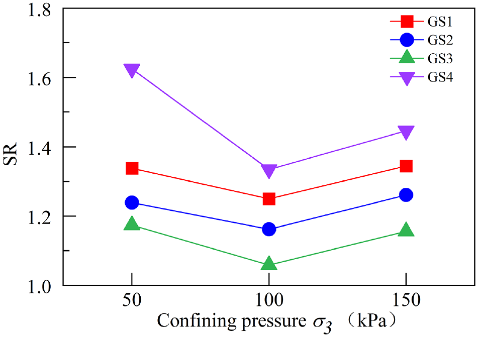
Relationship between deviatoric stress ratio and confining pressure.
Conclusion
The influences of different reinforcement locations, confining pressures, and numbers of reinforced layers on shear deformation performance of the geocell-reinforced railway roadbed were analyzed through reinforcement tests on filling materials of the railway roadbed. The following conclusions can be drawn.
1) At different reinforcement locations, the reinforcement effect of GS1 is better than those of GS2 and GS3. Under different confining pressures, the peak deviatoric stress always increases after geocell reinforcement. As the number of reinforced layers is increased, the peak deviatoric stress at failure of the reinforcement also increases significantly. The GS4 reinforced railway roadbed has the highest peak failure stress, which is superior to other reinforcement methods.
2) The internal frictional angle and cohesion of geocell-reinforced railway roadbed samples increase significantly, and the stiffness of geocell-reinforced samples is much greater than that of UR samples. As the confining pressure is increased, the stiffness of the railway roadbed at the same axial strain also increases. Under conditions involving different reinforcement locations and numbers of reinforced layers, the shear strength parameters and stiffness of the railway roadbed both increase. Laying five layers of geocells is superior to other forms of reinforcement with respect to shear strength parameters and stiffness.
3) Under conditions of different confining pressures, reinforcement locations, and numbers of reinforced layers, the energy absorption needed for the deformation and SR of GS1 are much better than those of GS2 and GS3. As the number of reinforced layers is increased (to that in case GS4), the energy absorption capacity and SR of the entire railway roadbed are enhanced to a significant extent. As the confining pressure increases, the energy absorption of geocell reinforcement is also increased while the SR is decreased. The geocell-reinforced railway roadbed exhibits the optimal reinforcement effect under a low confining pressure.
The proper use of geocells can effectively slow down the track settlement and particle degradation and increase the aggregate interlocking effect and frictional contact so as to optimize the performance of the railway roadbed. Nonetheless, future research needs to further explore reinforced crushed tire particles and larger size model boxes or field experiments to verify the effect of geocell reinforcement on the permanent deformation of the railway roadbed. In addition, more research is needed to evaluate the durability, maintainability, and recyclability of reinforcement technology.
Footnotes
Acknowledgements
The authors would like to thank the editors and reviewer for their careful review of this paper.
Author Contributions
The authors confirm contribution to the paper as follows: study conception and design: B. Cheng, J. Huang; data collection: B. Cheng, J. Huang; analysis and interpretation of results: B. Cheng, J. Huang, H. Wang, X. Li; draft manuscript preparation: B. Cheng, J. Huang, H. Wang. All authors reviewed the results and approved the final version of the manuscript.
Declaration of Conflicting Interests
The author(s) declared no potential conflicts of interest with respect to the research, authorship, and/or publication of this article.
Funding
The author(s) disclosed receipt of the following financial support for the research, authorship, and/or publication of this article: This work was supported by the National Natural Science Foundation of China (52109165) and the Natural Science Foundation of Hainan Province (521QN277).
Data Accessibility Statement
Some or all data, models, or code that support the findings of this study are available from the corresponding author on reasonable request.