



Abstract
Recommended guidelines were provided for the shape and size of aesthetic features added to roadside barriers in National Cooperative Highway Research Program Report No. 554, but limited full-scale crash testing has been performed on barriers with aesthetic features, especially in combination with sidewalks and pedestrian railings, each of which may contribute to increased propensity for vehicle snag, vehicle instabilities, and occupant risk metrics. A Hawaii Department of Transportation (HDOT) bridge rail design with vertical faces and aesthetic recessed panels was evaluated to Manual for Assessing Safety Hardware (MASH) TL-3 impact conditions in three configurations: stand-alone; in combination with a pedestrian handrail installed on the back side of the barrier system; and in combination with a pedestrian rail and 6 ft long x 6 in. tall sidewalk. The 34 in. tall aesthetic concrete bridge rail consisted of segments measuring 11 ft long at upstream and downstream ends and three 22 ft long, consecutive interior segments. MASH test designation Nos. 3-10 and 3-11 were performed on the stand-alone system and with the sidewalk and pedestrian rail, and test designation 3-11 was performed on the system on level terrain with handrail. Results indicated that the HDOT 34 in. tall aesthetic concrete bridge rail was crashworthy in all of the configurations evaluated.
Roadside hazards may be shielded by roadside barriers to protect the occupants of errant vehicles from striking a rigid fixed object, engaging slopes, drop-offs, or embankments, or entering into opposing lanes. When roads pass through scenic areas, it is often desirable to utilize barriers which are aesthetically pleasing and mesh well with the environment. Aesthetic treatments for barriers may be cosmetic, including coloring in the concrete or shaped faces, or may implement features which have additional functionality, such as gaps in open concrete bridge rail designs to facilitate drainage. However, aesthetic surface treatments may increase the risk of components of the vehicle snagging on the textured contours. Snagging could result in unacceptable occupant ridedown accelerations (ORAs), increased occupant impact velocities (OIVs), or increased potential for damage to the occupant compartment or damaged suspension components penetrating or deforming the floorpan.
In 1998, the Texas A&M Transportation Institute (TTI) evaluated the crashworthiness of a concrete bridge rail with window openings according to National Cooperative Highway Research Program (NCHRP) Report No. 350 impact conditions ( 1 , 2 ). The barrier utilized a vertical impact-side face with 8 x 18 in. tall windows spaced 18 in. apart. The total barrier height was 36 in. at the center of the domed pilaster (i.e., solid post), and 33 in. tall at the center of the rail. The rail was struck at 62.9 mph and 24.9 degrees in accordance with NCHRP Report No. 350 test designation No. 3-11, but the impact-side front wheel was deformed backward and upward into the occupant compartment resulting in unacceptable occupant compartment deformation. The maximum OIV and ORA values were 31.2 ft/s and 11.7 g’s, respectively. As a result, the test was not successful, as shown in Figure 1. The C411 bridge rail, which had a similar design, was successfully evaluated by TTI under MASH Test TL-2 impact conditions ( 3 ).
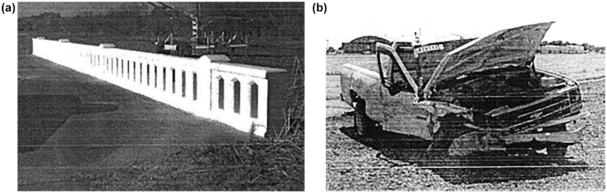
Photos from National Cooperative Highway Research Program (NCHRP) Report No. 350 TL-3 Evaluation of the T411 Bridge Rail ( 1 ): (a) T411 bridge rail, pre-test, (b) test vehicle, post-test.
The California Department of Transportation (Caltrans) subsequently performed a series of crash tests involving barriers with textured faces ( 4 ). Textured faces of the barriers included stone masonry and stone-shaped embossments or reliefs. Images of the barriers with textures are shown in Figure 2. All barrier textures were implemented on Caltrans “Type 60” concrete median barriers, with a 9.1 degree sloped face. The deep cobblestone, fluted rib, and mission arch textured barriers were 48 in. tall and the shallow cobblestone, deep cobblestone with relief, fractured granite, and drystack textured barriers were 56 in. tall. Full-scale crash tests of the Type 60 concrete median barriers with deep cobblestone with relief, fractured granite, drystack, and mission arch textures were acceptable, whereas the shallow cobblestone and deep cobblestone designs contributed to excessive snag and occupant compartment deformation, and the 45 degree fluted rib design contributed to wheel climb and vehicle instability resulting in the rollover of the 1100C test vehicle.

Aesthetic treatments evaluated by California Department of Transportation (Caltrans) ( 4 ): (a) deep cobblestone, (b) deep cobblestone with relief, (c) shallow cobblestone, (d) fractured granite, (e) drystack, (f) mission arch, (g) 45-degree fluted ribs.
Results of the textured barrier analysis led Caltrans to the following preliminary guidelines ( 5 ):
• Light-to-heavy sandblast textures: ○ Any pattern or texture with a maximum relief of 64 mm or less, located 610 mm or higher above the base of the barrier; the lower 610 mm shall be smooth or a “light-to-heavy sandblast” texture. ○ The pattern or texture on the upper face of the barrier shall have smooth (rounded or beveled) leading edges to prevent vehicle snagging.
• Geometric patterns inset into the face of the barrier 25 mm or less: ○ Chamfered or beveled edges to prevent vehicle snagging, especially on the downstream edges. ○ Such patterns shall not feature long upward-climbing edges that could contribute to wheel climb.
Building on the research from TTI and Caltrans, guidelines were published in the NCHRP Report No. 554 for the best practices associated with aesthetic surface treatments of rigid concrete barriers ( 6 ). Finite element analysis was performed on various barrier geometries to determine the potential for satisfying evaluation criteria provided in NCHRP Report No. 350 ( 2 ). Results of the geometrical, aesthetic guidelines from NCHRP Report No. 554 are shown in Figure 3.
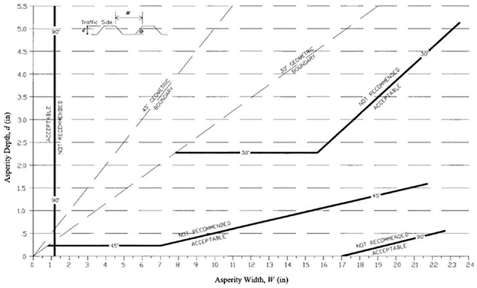
Final design guidelines for aesthetic surface treatments of safety shape concrete barrier ( 6 ).
Other types of aesthetic barrier used openings in the rail as the primary aesthetic feature. An example of an open, aesthetic concrete bridge rail system was evaluated at the Midwest Roadside Safety Facility (MwRSF) according to NCHRP Report No. 350 Test Level 5 (TL-5) impact conditions and evaluation criteria ( 7 ). The barrier shape is shown in Figure 4. The system included a cantilever bridge deck with the open concrete rail installed on top of the deck using Grade 60 epoxy-coated rebar. The aesthetic rail had a nearly vertical front face mounted on concrete posts and two longitudinal ribs. Test results of the NCHRP Report No. 350 TL-5 impact were acceptable and the system was determined to be crashworthy.
Aesthetic open concrete bridge rail evaluated to National Cooperative Highway Research Program Report No. 350 TL-5 impact conditions ( 7 ).
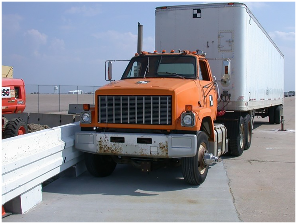
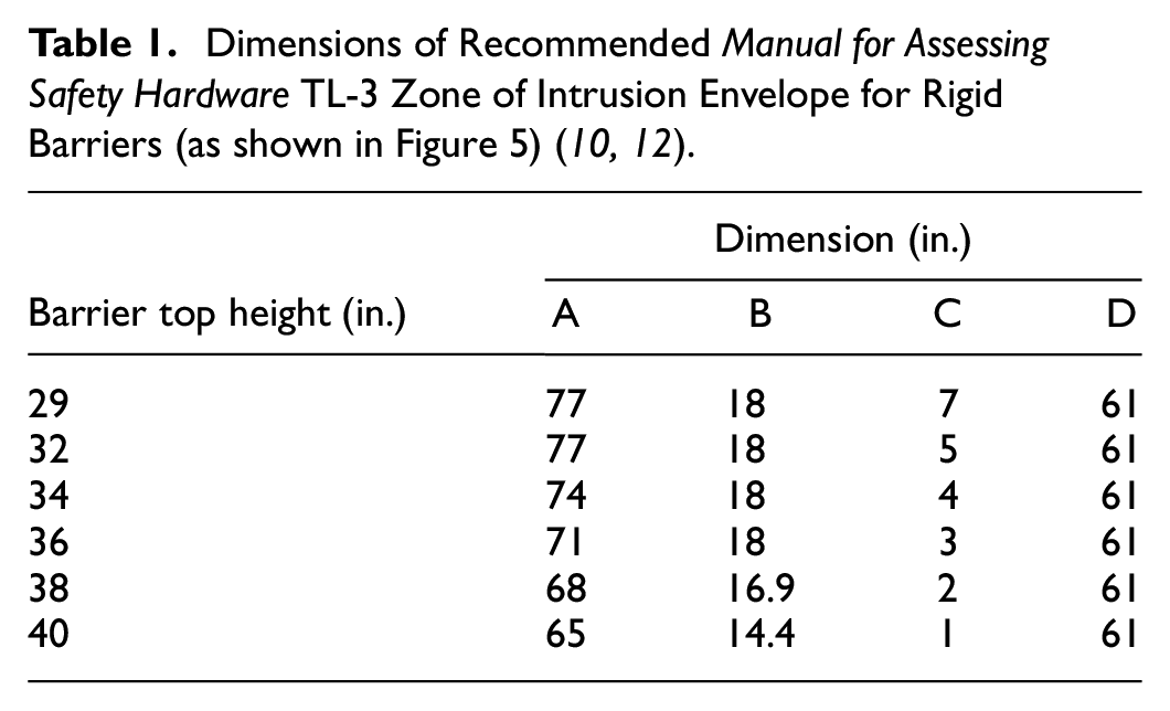
Hybrid bridge rails and combination bridge rails may also have aesthetic profiles and commonly allow vehicle occupants, pedestrians, and bicyclists to partially see through the barriers. The American Association of State Highway and Transportation Officials (AASHTO) LRFD Bridge Design Specifications define requirements for gap opening sizes and spacing of structural elements of combination bridge rails, including handrails ( 8 ). However, the openings between hybrid and combination rails may allow stiff components of impacting vehicles to extend into the space between structural rail elements and strike or snag on stiff rail members; the region of space which vehicle structural elements may extend above and behind the top traffic-side edge of the barrier is known as the “zone of intrusion” (ZOI). If snagging between stiff vehicle components and features in the ZOI lead to unacceptable occupant compartment deformation or excessive OIVs or ORAs, the system is not crashworthy according to AASHTO Manual for Assessing Safety Hardware (MASH) evaluation criteria ( 9 ). For this reason, even if the lower, rigid concrete parapet is determined to be crashworthy independently from the combination or hybrid rail, the systems must still be evaluated to MASH criteria to ensure crashworthiness. A diagram of the recommended ZOI envelopes for TL-3 rigid concrete barriers is shown in Figure 5 and the dimensions are given in Table 1 ( 10 , 11 ).

Several crashworthy combination bike or pedestrian rails have been evaluated to MASH TL-3 impact conditions, such as the North Carolina Department of Transportation (NCDOT) 2-bar bridge rail and bicycle railing and the Minnesota DOT combination pedestrian rail, as shown in Figure 6 ( 13 , 15 ). During test No. NCBR-2 of the NCDOT 2-bar bridge rail, the left-front corner of the test vehicle’s hood extended between the lower and upper aluminum longitudinal rails and contacted post No. 6, causing the hood to shear and peel longitudinally backward. The fender also snagged on the post and disengaged from the pickup truck. During test No. MNPD-3 of the Minnesota Department of Transportation (MNDOT) combination pedestrian rail, the right-front corner of the test vehicle’s hood and the right-front fender extended over the top of the 32 in. tall New Jersey shape concrete barrier and struck a post and two longitudinal beams of the combination rail system. Despite the impacts with the combination rail components during each test, both systems were determined to be acceptable according to MASH evaluation criteria. The NCDOT 2-bar bridge rail subsequently received a Federal Highway Administration (FHWA) eligibility letter ( 14 ).

Combination rails located in zone of intrusion which were affected during full-scale test: (a) NCBR-2: North Carolina Department of Transportation 2-bar bridge rail, (b) MNPD-3: Minnesota Department of Transportation combination rail, (c) NCBR-2 fender contact with rail, (d) MNPD-3 fender contact with rail, (e) NCBR-2 vehicle damage, (f) MNPD-3 vehicle damage, (g) NCBR-2 rail damage, (h) MNPD-3 rail damage (13–15).
To date, full-scale testing and computer simulation of aesthetic treatments for bridge rails to MASH evaluation criteria is limited, although there are many successfully tested combination rails which have aesthetic rails ( 16 , 17 ). While these combination rails may utilize aesthetic features, few are tested with and without combinations of sidewalks and pedestrian rails.
There exists a need for aesthetic crashworthy bridge rails which are suitable for use in locations where the aesthetics of the barriers must be considered. The Hawaii Department of Transportation (HDOT) wished to install several concrete bridge rails with aesthetic treatments similar to the Caltrans mission arch shape and compliant with recommendations provided in NCHRP Report No. 554. The first barrier was a 34 in. tall vertical concrete parapet with aesthetic recessed window panels. The second barrier consisted of a 42 in. tall vertical concrete parapet with a different recessed window style. HDOT requested that MwRSF conduct MASH crash test designation Nos. 3-10 and 3-11 on both railing systems to confirm MASH TL-3 crashworthiness. HDOT also requested evaluation of system variations which were consistent with pedestrian rail requirements. Results of the full-scale crash testing efforts on the HDOT 34 in. tall and 42 in. tall aesthetic concrete bridge rails with recessed window panels are described in this paper (18–20).
Few designs of roadside safety systems have been evaluated in combination with sidewalks. Generally, sidewalks are elevated 4 to 8 in. above the travel way and may be curbed. Recent research performed under NCHRP Project 22-39 indicated that 6 in. tall sidewalks were the most common when used in combination with roadside guardrail systems. When geometrical features are added to roadside barriers including bridge rails, the vehicle attitude at the time of impact with the feature may change: the suspension may be compressed or extended, the vehicle may experience roll toward or away from the barrier system, and the impact speed may change. Features which include sidewalks are therefore recommended for full-scale crash testing to confirm crashworthiness.
Evaluation of the HDOT 34 in. Tall Aesthetic Concrete Bridge Rail
Barrier Design Details
The HDOT 34 in. tall aesthetic concrete bridge rail was constructed in five segments separated by four expansion joints to allow for evaluation of the critical rail section at the expansion joints ( 18 ). The spacing between the expansion joints was limited to 22 ft, which was the smallest rail segment length between joints noted by HDOT. Larger rail segment lengths between expansion joints were considered less critical. The HDOT 34 in. tall aesthetic concrete bridge rail was installed on the concrete tarmac at the MwRSF outdoor test site rather than on a simulated bridge deck and overhang to simulate a strong bridge deck and bridge rail connection. However, the HDOT 34 in. tall aesthetic concrete bridge rail was constructed in a trench such that the back of the rail was 36 in. tall relative to the tarmac, and a concrete fill was then applied to the trench in front of the traffic-side face of the rail to simulate the 2 in. tall finished grade used by HDOT.
The bridge rail was 34 in. tall relative to the traffic-side tarmac and 10 in. wide at the top and the bottom. The top surface had 3/4 in. chamfered edges. Longitudinal aesthetic lines were cast with the barrier consisting of ½ in. deep, 45 degree V-notches located 7 in. below the top surface and 9 in. above the bottom surface on the traffic- and back-side faces. Aesthetic recessed windows measuring 60 in. wide x 15 in. tall x ½ in. deep were cast into both the traffic-side and back-side faces. The edges of the panels transitioned to the face of the rail using a 2H:1V slope. The aesthetic recesses in the face of the barrier were consistent with the guidelines provided in NCHRP Report No. 554.
The concrete mix for the bridge rail sections required a minimum 28-day compressive strength of 4,000 pounds per square inch (psi). Two concrete cylinder compression tests were conducted, with 13-day compressive strength results of 4,000 psi and 4,260 psi. Steel reinforcement in the barrier consisted of American Society for Testing and Materials (ASTM) A615 Grade 60 rebar. Each concrete bridge rail segment consisted of eight No. 5 longitudinal bars (four per face) that were vertically spaced 10 in. apart. Vertical stirrups were also provided using No. 5 rebar, which were spaced on 12 in. centers on the back-side face and on 6 in. centers on the traffic-side face. Vertical reinforcement bars were anchored to an existing concrete tarmac on both the traffic-side and back-side faces to a depth of 8 in. and epoxied with Hilti HIT RE-500 V3 to develop the full tensile strength of the bar. The minimum bond strength of the epoxy adhesive was 1,560 psi after a 2-day cure.
Design details for the HDOT 34 in. tall aesthetic concrete bridge rail are shown in Figure 7.

Design details of Hawaii Department of Transportation 34 in. tall aesthetic concrete bridge rail: (a) Elevation view, (b) segment details, (c) reinforcement details, (d) shape contour and profile, (e) aesthetic chamfer details, (f) test article ( 18 ).
MASH TL-3 Crash Test Evaluation Criteria
Aesthetic concrete bridge rails must satisfy impact safety standards to be declared eligible for federal reimbursement by the FHWA for use on the National Highway System (NHS). For new hardware, these safety standards consist of the guidelines and procedures published in MASH (AASHTO 2016). According to TL-3 of MASH, longitudinal barriers must be subjected to two full-scale vehicle crash tests, as summarized in Table 2. Note that both prescribed full-scale crash tests—test designation Nos. 3-10 and 3-11—were conducted and reported here, along with an evaluation of the bridge railing system. The reference location selected for the critical impact point (CIP) was at an expansion joint between consecutive bridge rail segments to maximize the propensity for snagging on the exposed joint.
Manual for Assessing Safety Hardware 2016 TL-3 Crash Test Conditions for Longitudinal Barriers ( 9 )

Evaluation criteria for full-scale vehicle crash testing are based on three appraisal areas: 1) structural adequacy, 2) occupant risk, and 3) vehicle trajectory after collision ( 9 ). Criteria for structural adequacy are intended to evaluate the ability of the HDOT 34 in. tall aesthetic concrete bridge rail to contain and safely redirect impacting vehicles. Controlled lateral deflection of the test article is acceptable. “Occupant risk” evaluates the degree of hazard to occupants in the impacting vehicle. “Post-impact vehicle trajectory” is a measure of the potential of the vehicle to result in a secondary collision with other vehicles, fixed objects, or both, thereby increasing the risk of injury to the occupants of the striking vehicle, other vehicles, or both. The full-scale vehicle crash tests documented here were conducted and reported in accordance with the procedures provided in MASH 2016.
Test No. H34BR-1: MASH Test Designation No. 3-10
The first full-scale crash test of the HDOT 34 in. tall aesthetic concrete bridge rail was performed in accordance with MASH test designation No. 3-10. A 2,430 lb, 2009 Hyundai Accent small car struck the HDOT 34 in. tall aesthetic concrete bridge rail at a speed of 62.4 mph and at an angle of 25.7 degrees. The vehicle was captured and redirected by the 34 in. tall bridge rail. During the redirection of the vehicle, the right-front fender and right-front wheel experienced snag on the expansion joint and the edge of the aesthetic asperities downstream from impact. The snag was sufficient to push the right-front tire backward and crush the front portion of the right-front fender. However, the snag of the vehicle components did not pose a risk to the vehicle occupant compartment, nor did it pose a hazard from the velocity change or deceleration of the vehicle. The measured impact severity of test no. H34BR-1 was 59.2 kip-ft, which was greater than or equal to the 51 kip-ft criterion defined in MASH 2016 for test designation No. 3-10.
It should be noted that, at the time of the crash test, a national discussion was underway in the U.S. because subcompact or compact production cars in the targeted weight range were no longer consistent with MASH vehicle specifications for dimensions including track width, wheelbase, and height. Although MASH 2016 describes that test vehicles used in crash testing should be no more than six model years old, a provision was made to allow older vehicles which still met MASH specifications to be used until a new guideline was established. The 2009 Hyundai Accent was used instead of the 2013 model for the crash test because the 2013 model vehicle geometry did not comply with the recommended vehicle dimension ranges specified in Table 4-1 in MASH 2016.
Barrier and vehicle damage are shown in Figure 8. Barrier damage was minor and consisted of minor cracking, spalling, and contact marks on the parapet and minor cracking and spalling at the expansion joint between barrier Nos. 3 and 4. Damage to the vehicle was moderate. The majority of the damage was concentrated on the right-front fender and right-front wheel of the vehicle where the impact had occurred. A small section of the seam where the floor pan and toe pan connected near the left-front corner of the right-side floor pan split as a result of floor pan deformation. It should be noted that the passenger side window fractured, and a large tear was visible in the vehicle windshield. Review of the high-speed video revealed that the side window damage was a result of crush of the side of the vehicle door and not because of direct contact with the test article. Similarly, video data showed that the windshield tearing was a result of crushing of the right front corner of the windshield which propagated a shear crack through the glass and the liner. Neither of these items were in violation of the MASH 2016 criteria as none of the damage occurred because of contact with the test article or debris, nor was there the potential for the barrier to intrude into the occupant compartment. As a result, all MASH evaluation criteria were satisfied for test No. H34BR-1.
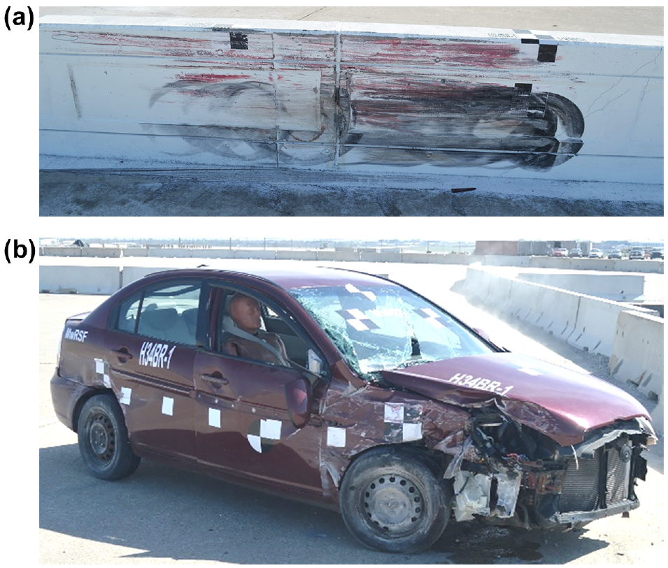
Barrier and vehicle damage, test No. H34BR-1: (a) test article damage, (b) vehicle damage ( 18 ).
Test No. H34BR-2: MASH Test Designation No. 3-11
Test no. H34BR-2 consisted of a 5,001 lb, 2016 Dodge Ram 1500 striking the HDOT 34 in. tall aesthetic concrete bridge rail at 64.0 mph and 25.4 degrees. The actual point of impact was 5/16 in. upstream from the targeted impact location. The measured impact severity of test No. H34BR-2 was 126 kip-ft, which fell into the acceptable range of greater than or equal to 106 kip-ft as defined in MASH 2016 for test designation No. 3-11. After impact, the right-front bumper and wheel were crushed inward and the vehicle passed by the vertical lip of the aesthetic recess and the expansion joint with minor snagging. The vehicle was smoothly redirected and came to rest 191 ft 10 in. downstream from the impact point after brakes were applied.
Barrier and test vehicle damage are shown in Figure 9. Barrier damage was minor and consisted of contact marks on the front face of the concrete segments, minor spalling of the concrete, and concrete cracking. The length of vehicle contact along the barrier was approximately 12 ft 9 in. The majority of the vehicle damage was concentrated on the right-front corner and right side of the vehicle where the impact had occurred. The right-front fender, lower control arm, steering arm, and wheel rim were crushed backward and inward toward the vehicle, and the right front door extended outward from the frame at the top sill. It should be noted that the window on the right-front side was shattered, but the damage was a result of crush of the side of the vehicle door and not because of direct contact with the test article. Thus, the side window damage was not in violation of the MASH criteria as it did not occur because of contact with the test article or debris. All MASH evaluation criteria were satisfied for test no. H34BR-2.

Barrier and vehicle damage, test No. H34BR-2: (a) test article damage, (b) vehicle damage ( 18 ).
System Variations: Combination Pedestrian Rail and Sidewalk
Pedestrian Handrail Design Details
HDOT wanted to use the successful 34 in. tall aesthetic concrete bridge rail in combination with a pedestrian rail on a broader variety of roadways. HDOT designed a pedestrian rail to be mounted to the back side of the 34 in. tall aesthetic concrete bridge rail using a post-installed epoxy construction. Because the system would function both as a containment barrier for errant vehicles and provide pedestrian accommodations, it was named the “HDOT 34 in. tall aesthetic combination rail.” Design details of the HDOT 34 in. tall aesthetic combination rail are shown in Figure 10 ( 19 ).
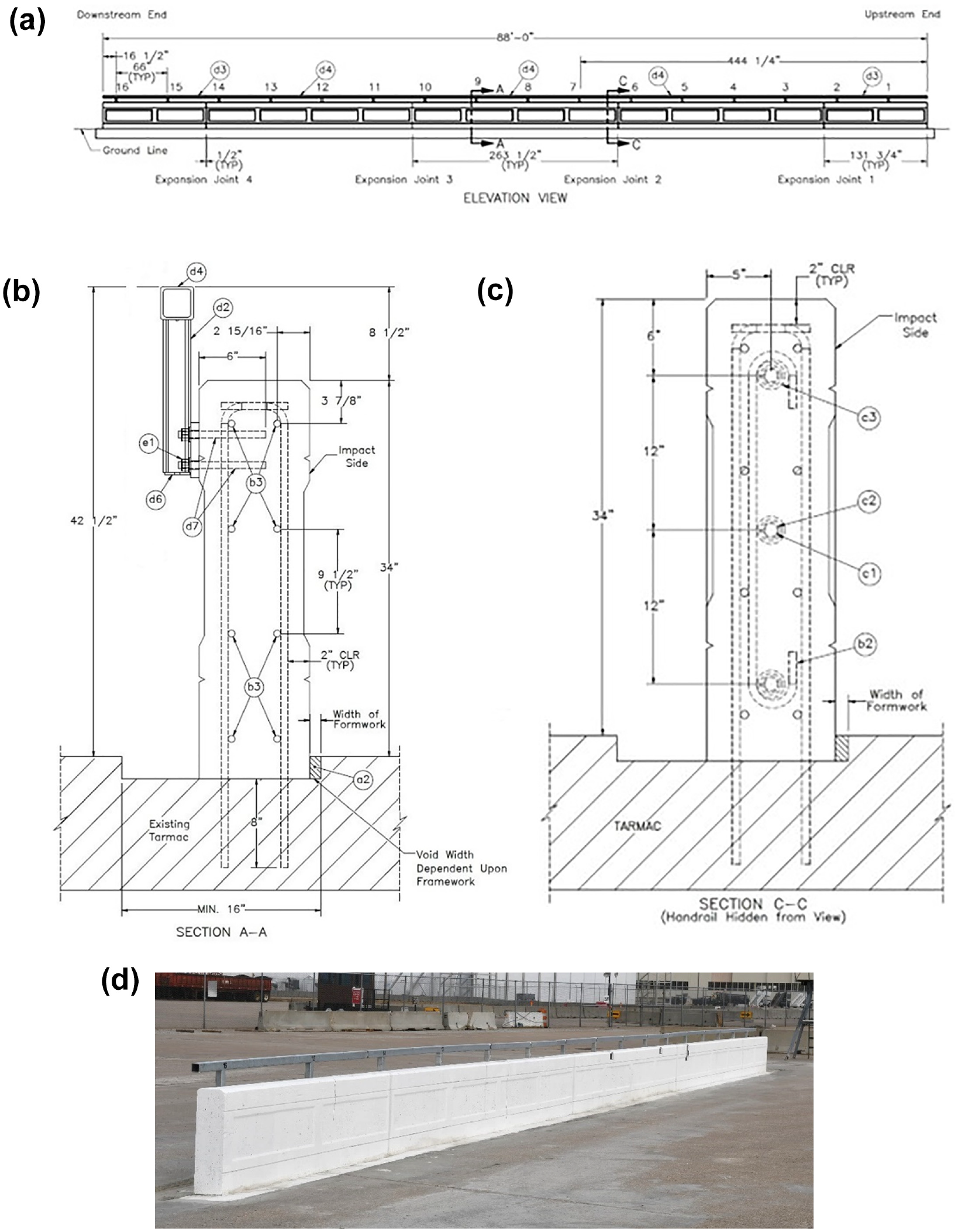
Design details, Hawaii Department of Transportation 34 in. tall aesthetic concrete combination bridge rail with pedestrian handrail: (a) Elevation view, (b) pedestrian rail connection details, (c) reinforcement and shape details, (d) test article ( 19 ).
The total height of the handrail above the bridge deck was 42½ in. The handrail consisted of a welded tube, post, and baseplate assembly. The rail consisted of hollow structural steel (HSS) 3x3x¼ by 21 ft 11 in. long steel tubes, which were welded using a ¼ in. fillet weld all around to HSS 2½x2½x¼ by 7 in. long tube posts. The tube posts were welded to 8 x 5 x 3/4 in. thick ASTM A36 steel base plates with a 3/16 in. fillet weld on both sides of the post. The splices consisted of a HSS 2x2x¼ by 7 in. long tube with 7 x 1½ x 3 /16 in. thick shims inserted 2 in. into the downstream side of the handrail tube and welded on all sides with a 3/16 in. fillet weld. As a result, approximately 1 in. of the splice tube assembly was exposed at the expansion joint, and the remaining 4 in. of the splice tube assembly protruded into the adjacent handrail end. The spacing between handrail posts was 66 in.
The offset between the front traffic-side face of the barrier and the front face of the pedestrian rail was approximately 10 in. This offset would place the vertical posts of the pedestrian rail within the estimated 18 in. wide ZOI recommended by Stolle ( 10 , 11 ). High-speed video analysis of test Nos. H34BR-1 and H34BR-2 indicated that the pickup truck hood and right-front fender extended approximately 17½ in. laterally into the barrier’s ZOI during test No. H34BR-2, but the small car extended only to a maximum of approximately 1½ in. over the barrier surface during test No. H34BR-1, as shown in Figure 11. As a result, MASH test designation No. 3-11 was likely to produce vehicle-to-pedestrian rail impact, but MASH test designation No. 3-10 would not vary from the results of test No. H34BR-1. Therefore, only MASH test designation No. 3-11 was recommended on the HDOT 34 in. tall aesthetic combination bridge rail.
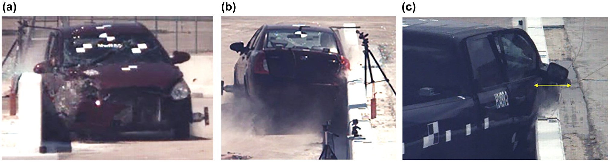
Maximum vehicle protrusion into zone of intrusion (ZOI), Hawaii Department of Transportation 34 in. tall aesthetic concrete bridge rail ( 19 ): (a) front view and (b) back view of estimated 1.5 in. maximum vehicle protrusion into ZOI during test No. H34BR-1, (c) 17 in. maximum vehicle protrusion into ZOI during test No. H34BR-2.
One post of the handrail was installed 16½ in. from the upstream end of each parapet to maximize the potential for snag adjacent to a splice location. This configuration represented a worst-case scenario for the pedestrian rail post installed near a splice.
Test No. HP34-1: MASH Test Designation No. 3-11
Initial vehicle impact was to occur 85 in. upstream from the upstream side face of post No. 7, which was selected based on the point of maximum extension of the hood and fender during test No. H34BR-1 ( 18 , 19 ). The 5,002 lb pickup truck struck the HDOT 34 in. tall aesthetic combination bridge rail at a speed of 62.2 mph and at an angle of 24.9 degrees. At 0.040 s after impact, the right-front corner of the hood and fender contacted the upstream face of post No. 7 of the pedestrian rail. The vehicle was smoothly redirected and exited the barrier at 45.8 mph and 4.7 degrees. After brakes were applied, the vehicle came to rest 194 ft downstream from the point of impact and 12 ft laterally behind the barrier, facing downstream.
Damage to the barrier was minimal and consisted of contact marks on the front face of the concrete segments, spalling of the concrete, and concrete cracking, in addition to contact marks on the upstream face of handrail post No. 7, as shown in Figure 12, e and f .
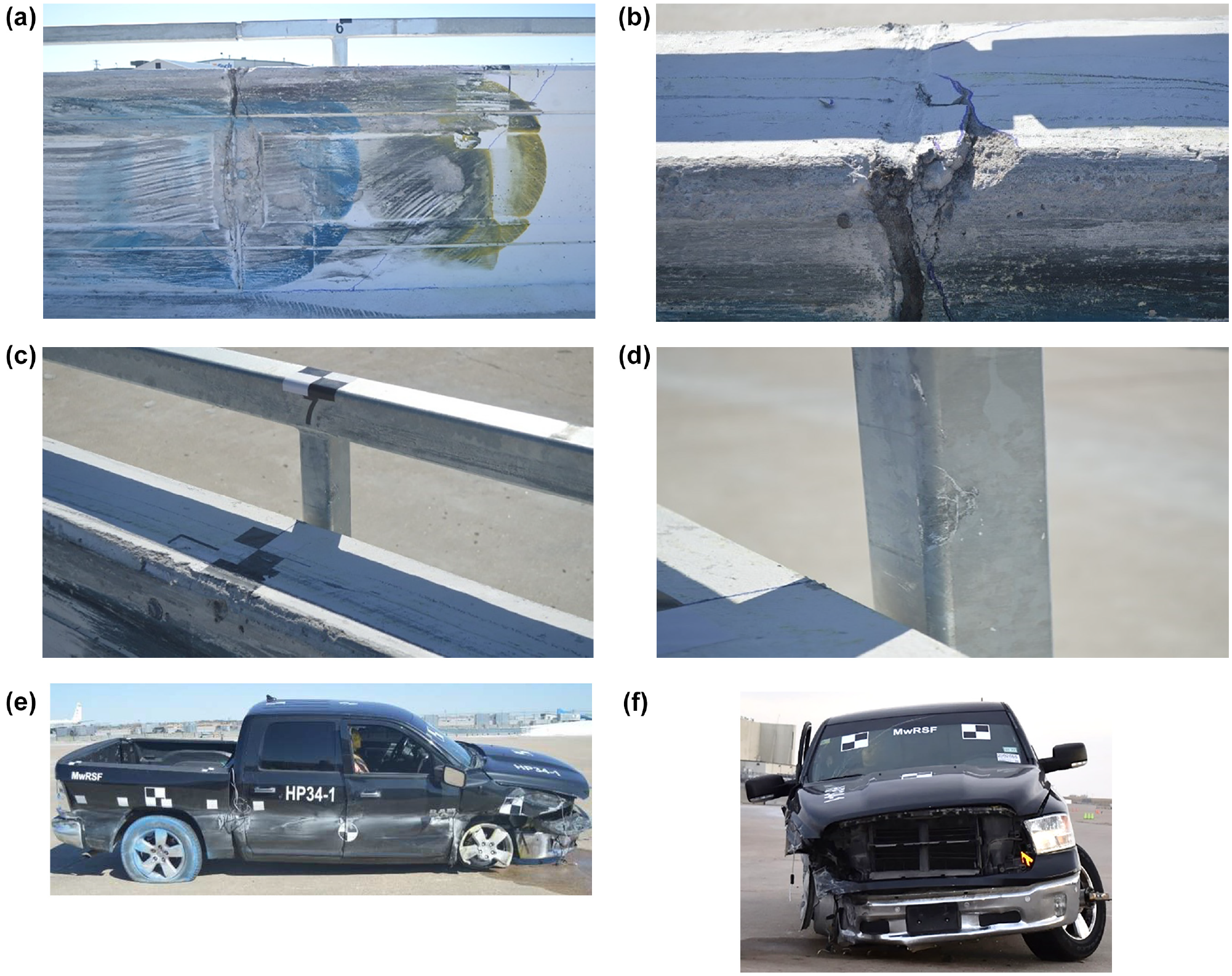
Barrier and vehicle damage, test No. HP34-1: (a) test article damage, (b) cracking at expansion joint, (c) pedestrian rail damage at point of impact, (d) detail view of contact with pedestrian rail, (e) side and (f) front views of vehicle damage ( 19 ).
The top, impact-side edge of expansion joint No. 2 was chipped on barrier segments Nos. 2 and 3, resulting in a 3 in. tall x 5 in. wide x 6 in. deep crack on barrier segment No. 2 at the downstream expansion joint. The length of vehicle contact along the barrier was approximately 12 ft 9 in., which started from 95⅛ in. upstream from the upstream side of post No. 7 and extended to approximately 8 in. upstream from the upstream face of post No. 8.
The damage to the vehicle was moderate and was concentrated on the right-front corner and right side of the vehicle where the impact occurred, as shown in Figure 12, e and f .
The right-front bumper corner was crushed inward, and the right-front headlight assembly was damaged and disengaged. The right-front fender, right door, and right-side box panels were dented and crushed along the entire length at a height corresponding to the top, impact-side edge of the parapet. The right-side door frame was bent and disengaged from the cab at the top seam, and the right-front windowpane was shattered and disengaged. The windshield was cracked, extending from the windshield wiper connection, but cracking was limited.
Detached elements, fragments, or other debris from the test article did not penetrate or show potential for penetrating the occupant compartment, or present an undue hazard to other traffic, pedestrians, or work-zone personnel. Deformations of, or intrusions into, the occupant compartment that could have caused serious injury did not occur. The test vehicle did not penetrate nor ride over the barrier and remained upright during and after the collision. Vehicle roll, pitch, and yaw angular displacements were deemed acceptable, because they did not adversely influence occupant risk nor cause rollover. After impact, the vehicle exited the barrier at an angle of 4.7 degrees, and its trajectory did not violate the bounds of the exit box. Therefore, test No. HP34-1 was determined to be acceptable according to the MASH 2016 safety performance criteria for test designation No. 3-11.
Sidewalk Design Details
HDOT developed an additional design variation which incorporated a 6 ft sidewalk. Design details of the HDOT 34 in. tall aesthetic combination rail with sidewalk are shown in Figure 13 ( 20 ). The barrier and pedestrian rail design details were the same for the HDOT 34 in. tall aesthetic combination rail, except that the vertical reinforcement in the barrier was routed through the sidewalk and into the MwRSF tarmac to represent the bridge deck. The sidewalk was 82 in. wide including a 10 in. wide x 7½ in. tall flat surface beneath the bridge rail along with a downward slope of 1V:48H leading away from the bridge rail. Steel reinforcement in the sidewalk consisted of ASTM A615 Grade 60 rebar. Seven longitudinal bars were spaced on 12 in. centers and lateral bars were spaced on 9 in. centers. Lateral rebar was embedded 9⅜ in. into the bridge rail and 8 in. into the tarmac. Vertical stirrup reinforcement in the bridge rail was anchored through the sidewalk to an existing concrete tarmac on both the traffic-side and back-side faces to a depth of 8 in. and epoxied with Hilti HIT RE-500 V3 to develop the full tensile strength of the bars.

Design details, Hawaii Department of Transportation 34 in. tall aesthetic combination rail with 6 ft sidewalk: (a) Elevation view, (b) barrier and sidewalk reinforcement details, (c) pedestrian rail and barrier reinforcement details, (d) test article ( 20 ).
Test No. HP34S-1: MASH Test Designation No. 3-11
Initial vehicle impact was to occur 85 in. upstream from the upstream face of post No. 7 on the concrete parapet, which was selected using video analysis from previous tests with sidewalks to maximize the probability of wheel snag and vehicle interaction with the pedestrian handrail ( 20 ). The 5,045 lb pickup truck struck the sidewalk at a speed of 65.7 mph and an angle of 25.2 degrees and struck the barrier at a speed of 63.6 mph and an angle of 23.7 degrees. This test vehicle’s speed at impact with the sidewalk exceeded the recommended limits shown in MASH for impact speed and impact severity value, but when behavior of the system is more critical at elevated speeds, tests with excessive speed are still acceptable. For this system, increased speed at impact with the curb and barrier system is likely to generate a more severe reaction and engagement between the vehicle and the barrier, as well as promoting vehicle fender and body panel extension into the ZOI. Therefore, the elevated impact speed was acceptable. The vehicle traversed the curb which caused the left-front and left-rear tires to deflate, and the vehicle was smoothly captured and redirected. The vehicle exited the barrier traveling 41.3 mph and at an angle of 9.1 degrees. After brakes were applied, the vehicle came to rest 216.0 ft downstream from the point of impact with the sidewalk and 31.8 ft laterally in front of the sidewalk. The point of impact was at the targeted impact point.
Section 5.3 of MASH 2016 provides guidance for addressing geometric features. As the tested system included a geometric feature in the form of a sidewalk, MASH 2016 criteria are outlined below and were addressed accordingly:
1) The vehicle should remain upright during and after collision. The maximum roll and pitch angles are not to exceed 75 degrees.
2) Compute average accelerations in the longitudinal and lateral directions for each consecutive 50 ms period for the duration of the event.
3) If the average longitudinal or lateral acceleration computed in Step 2 exceeds 2 g’s during any 50 ms period, calculate the OIV and ORA values at the beginning of the period over which the average acceleration was computed, and evaluate the results according to Criteria H and I of Table 5-l B.
The 2270P pickup truck interaction with the curb did not exceed 2.0 g’s within a 50 ms period around the time of impact; therefore, event start time, t = 0, occurred at the time of impact with the bridge rail.
Barrier damage consisted of contact marks on the front face of the concrete segments and minor concrete spalling and cracking, as shown Figure 14. The length of vehicle contact along the barrier was approximately 14 ft 11 in., which spanned across barrier segment Nos. 2 and 3. There was minor gouging in the concrete near the impact point and along the contact length and gouging at the expansion joint immediately downstream from the impact point. Vehicle damage was moderate, as shown Figure 14. The left side of the front bumper was crushed inward and backward. The left-front fender was crushed inward toward the centerline of the vehicle and engine compartment. The left-front wheel was disengaged from the vehicle, the tire was punctured and deflated, and the rim was fractured along three of the five spokes extending from the hub. The left-rear wheel rim was fractured and separated into multiple pieces. The tire remained engaged with the fractured pieces of the rim. The left-front and left-rear fenders, both left-side door panels, and the left-rear bumper were crushed inward and scraped. All MASH evaluation criteria were satisfied for test No. HP34S-1.
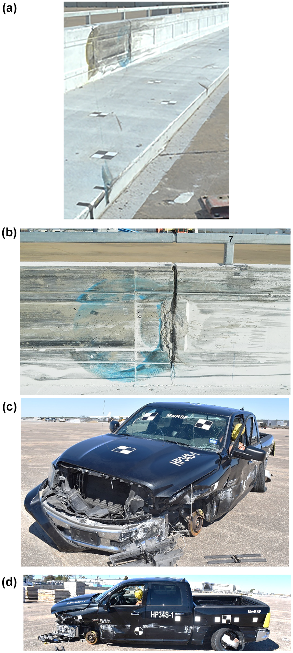
Barrier and vehicle damage, test No. HP34S-1: (a) system damage, (b) detail view of damage at expansion joint, (c) oblique and (d) side view of vehicle damage ( 20 ).
Test No. HP34S-2: MASH Test Designation No. 3-10
The 2,413 lb small car struck the sidewalk at a speed of 62.0 mph and at an angle of 25.0 degrees and struck the barrier at a speed of 60.2 mph and an angle of 22.8 degrees. Initial vehicle impact was to occur 43 in. upstream from the upstream face of post No. 11, and the actual point of impact was 2.4 in. downstream from the targeted impact point. The vehicle struck the curb and the left-front striking tire deflated immediately after impact. The 1100C small car interaction with the curb did not exceed 2 g’s during any 50 ms period. Therefore, event start time, t = 0 s, occurred at the time of impact with the bridge rail. The vehicle was partially launched from the sidewalk into the barrier and was smoothly captured and redirected. After brakes were applied, the vehicle came to rest 183.8 ft downstream from impact and 11.0 ft laterally from the front of the sidewalk.
Damage to the barrier was minimal, as shown in Figure 15. Barrier damage consisted of contact marks on the front face of the concrete segments and concrete gouging. The length of vehicle contact along the barrier was approximately 9 ft 11 in., which spanned across barrier segment Nos. 3 and 4. A ½ in. deep x 15 in. tall gouge initiated on the slope in the recessed window immediately upstream from expansion joint No. 3 where steel rebar was exposed. The pedestrian rail was not affected during test no. HP34S-2. Vehicle damage was moderate, as shown in Figure 15, and consisted of crushed bumper and fender components, contact marks along the side of the vehicle, fractured wheel rims, and damage to the lower left-front lower control arm.
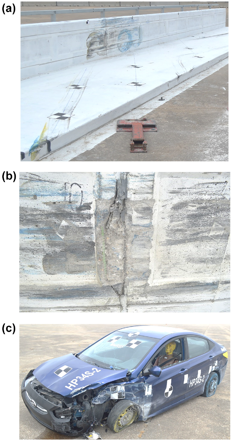
Barrier and vehicle damage, test No. HP34S-2: (a) system damage, (b) detail view of damage at expansion joint, (c) vehicle damage ( 20 ).
Discussion
All of the design variations of the HDOT 34 in. tall aesthetic concrete bridge rail were determined to be successful. Test results are summarized in Table 3. Although the pickup truck contacted post No. 7 of the system during test Nos. HP34-1 and HP34S-1, snag did not result in unacceptable occupant compartment deformation, vehicle accelerations, or vehicle instability. Test summary pages are shown in Figures 16 through 20. The maximum lateral extensions of the vehicles during test Nos. H34BR-1, H34BR-2, HP34-1, HP34S-1, and HP34S-2 are shown in Figure 21.
Summary of Manual for Assessing Safety Hardware Evaluation Criteria for Tests Involving the Hawaii Department of Transportation 34 in. Tall Aesthetic Concrete Bridge Rail
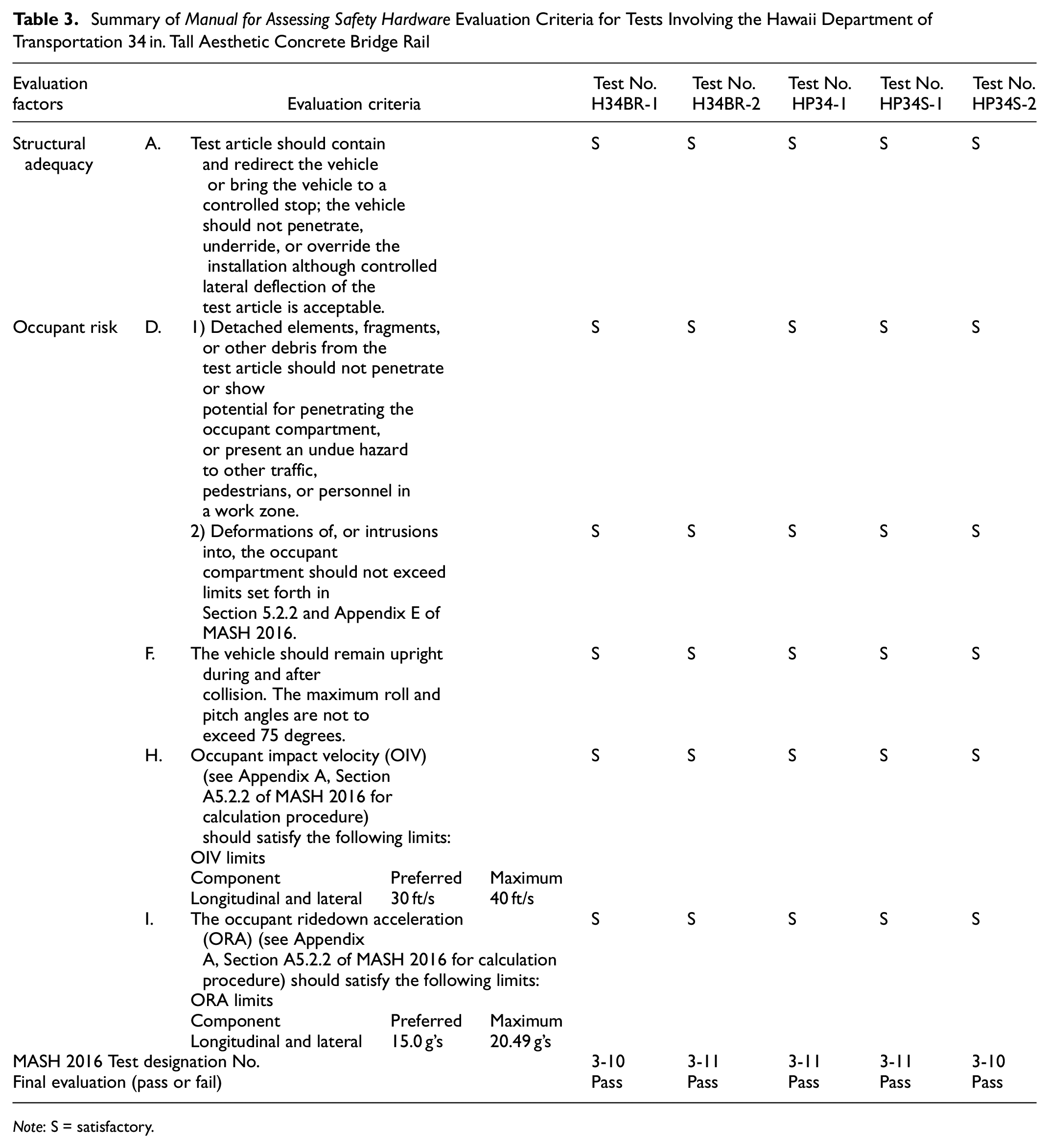
Note: S = satisfactory.
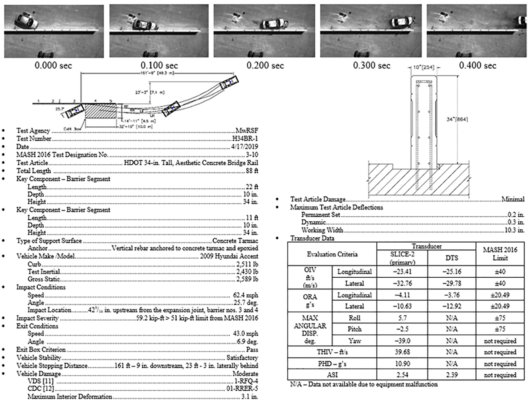
Summary of test results and sequential photographs, test No. H34BR-1.
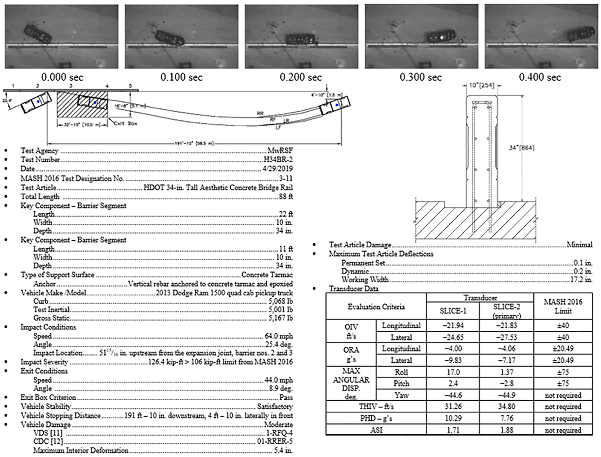
Summary of test results and sequential photographs, test No. H34BR-2.
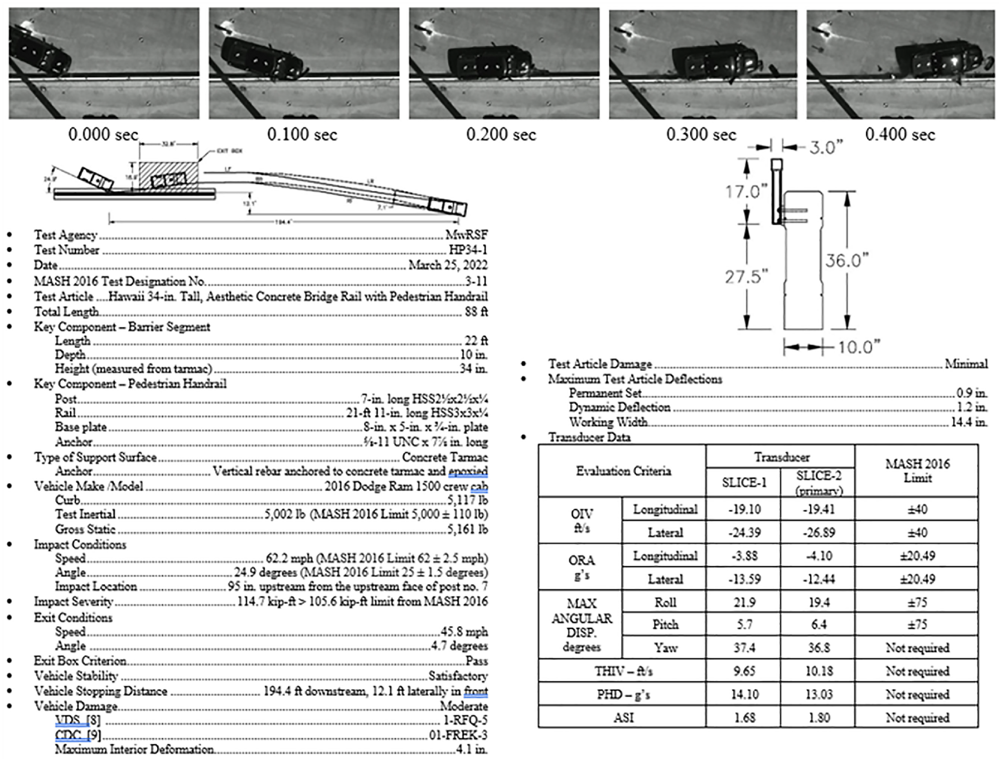
Summary of test results and sequential photographs, test No. HP34-1.
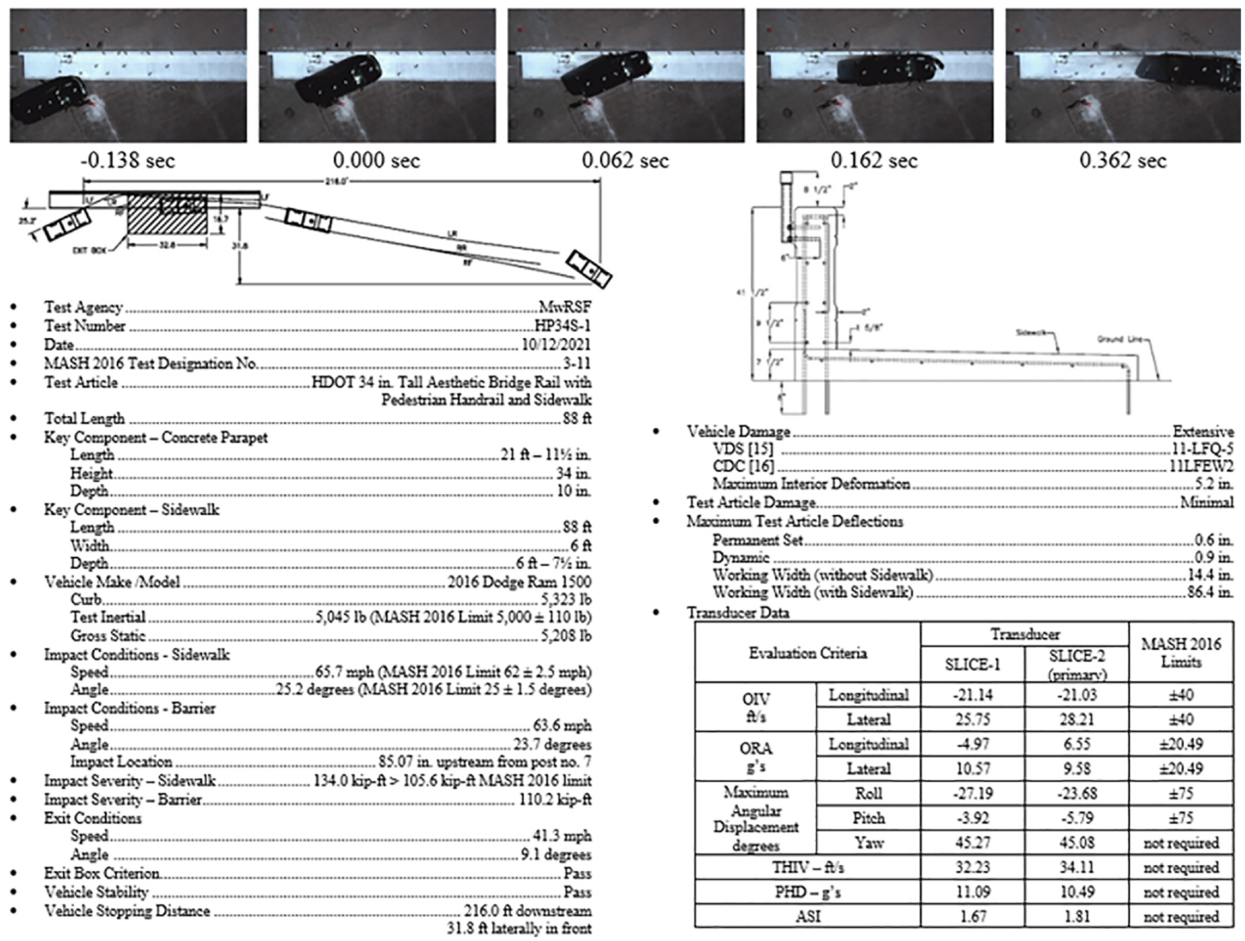
Summary of test results and sequential photographs, test No. HP34S-1.

Summary of test results and sequential photographs, test No. HP34S-2.
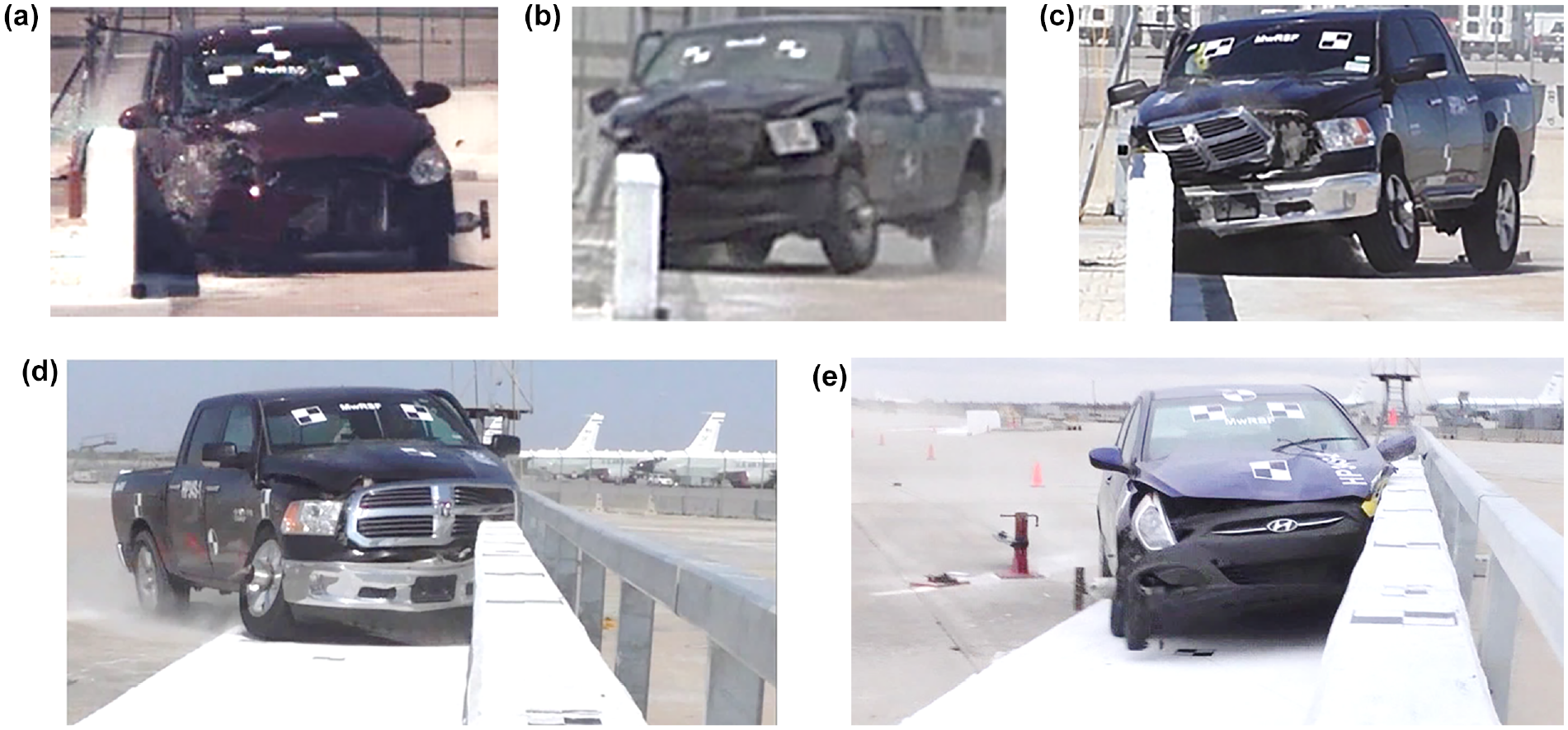
Maximum lateral extent of vehicle intrusion into zone of intrusion and pedestrian handrail contact, Hawaii Department of Transportation 34 in. tall aesthetic concrete bridge rail systems: (a) H34BR-1, (b) H34BR-2, (c) HP34-1, (d) HP34S-1, (e) HP34S-2.
The backside-mounted pedestrian rail had minimal effect on the vehicle’s redirection during any impact. As a result, it is likely that the HDOT 34 in. tall aesthetic bridge rail with 6 ft sidewalk and without a pedestrian rail would also likely be crashworthy according to MASH evaluation criteria. MASH test designation No. 3-10 was not performed on the HDOT 34 in. tall aesthetic combination rail without sidewalk. However, results of test Nos. H34BR-1 and HP34S-2 both indicated that the maximum lateral extent of a structural component of the vehicle above and behind the top surface of the barrier was minimal, and results of MASH test designation 3-10 were unlikely to be different from test results of test No. H34BR-1.
During this evaluation, no approach guardrail transitions were considered and impacts were executed within the barrier’s length of need. A crashworthy transition should be utilized in combination with the barrier system and pedestrian rail.
For each test, a rigid foundation was used to anchor the bridge rail segments. Bridge decks used in combination with the HDOT 34 in. tall aesthetic concrete bridge rail should ensure that adequate reinforcement and connections are used to anchor the bridge rail to the deck and to prevent excessive deck damage.
Selection of which impact side is based on the general assumption that there are no performance-based differences for left- or right-side impacts; it is assumed that the impact performance of the system and vehicle will be symmetrical. Crash test systems are laid out on the MwRSF test site to optimize use of the available space and runout trajectory. Because different systems evaluated in this study were installed at different times, some of the full-scale crash tests were performed with the right side leading, and others with the left side leading.
Conclusions
Three variations of the HDOT 34 in. tall aesthetic concrete bridge rail were evaluated using full-scale crash testing. A standalone configuration was evaluated according to MASH test designation Nos. 3-10 and 3-11. A configuration with a backside-mounted pedestrian rail was evaluated to MASH test designation No. 3-11. A final configuration with a curb, sidewalk, and pedestrian rail was evaluated to MASH test designation Nos. 3-10 and 3-11. Each of the full-scale crash tests were determined to be successful. The aesthetic recesses used with the HDOT 34 in. tall aesthetic bridge rail were consistent with the guidelines presented in NCHRP Report No. 554. Results indicated that the aesthetic concrete bridge rail was crashworthy in several configurations and may be used in locations adjacent to the NHS.
Footnotes
Acknowledgements
The authors would like to thank MwRSF test site technicians and engineers for constructing the barriers and performing the full-scale crash tests.
Author Contributions
The authors confirm contribution to the paper as follows: study conception and design: C. Stolle, R. Bielenberg, R. Faller, D. Takiguchi; data collection: C. Stolle, R. Bielenberg. S. Changizian; analysis and interpretation of results: C. Stolle, R. Bielenberg. S. Changizian; draft manuscript preparation: C. Stolle. All authors reviewed the results and approved the final version of the manuscript. (Note: D. Takiguchi was not available to confirm co-authorship, but the corresponding author C. Stolle affirms that D. Takiguchi contributed to the paper and vouches for his co-authorship status.)
Declaration of Conflicting Interests
The author(s) declared no potential conflicts of interest with respect to the research, authorship, and/or publication of this article.
Funding
The author(s) disclosed receipt of the following financial support for the research, authorship, and/or publication of this article: The authors would like to acknowledge the Hawaii Department of Transportation for funding this research study under NDOT contract numbers 67167 and 68212.
