



Abstract
This paper provides an historical review of maritime mobile radio communications systems as a primary means of ensuring the safety and security of ships at sea. Safety at sea has always been a priority for seamen and shippers. Distress alerts at sea caused by the blind forces of Mother Nature or, more commonly, by human factors have occurred over many centuries, as seafarers often set sail with inadequate information about their course, navigation and weather conditions. Until the late nineteenth century, only audio and visual transfers of information from point to point were used. From then on, however, new methods, such as news and information via wire and then by radio communications systems, were introduced. So long as safety standards are met, it is also important to test innovations and technology transfer to develop devices that are more reliable than mobile radio communications.
The word ‘communications’ describes the social process of information exchange and covers the human need for direct contact and mutual understanding. In general, telecommunications are the conveyance of intelligence in some form of signal, sign, sound or electronic means from one point to a distant second point. Thus, in ancient times, that intelligence was communicated with the aid of audible callings, fire and visible vapor or smoke and image signals. Humankind has gone a long way from the first audio and visual forms of communication, which were used for several thousand years. In the meantime, primitive types of communication between individuals or groups of people have been invented. Hence, as impressive as this achievement was, the development of more reliable communications and so, wire and radio, had to wait a couple of centuries more.
The invention of the telegraph in 1844 and the telephone in 1876 harnessed the forces of electricity to allow the voice to be heard beyond shouting distance for the first time. The British physicist, Michael Faraday, and the Russian academic, E.H. Lenz, experimented with electric and magnetic phenomena and formulised a theory of electromagnetic (EM) induction. Thus, the British physicist, James C. Maxwell, published in 1873 his classical theory of electromagnetic radiation, proving mathematically that electromagnetic waves travel through space with a speed precisely equal to that of light. In 1886, the famous German physicist, Heinrich Rudolf Hertz, experimentally proved Maxwell’s theoretical equations. Thus, during Hertz’s studies in 1879, his mentor physicist Hermann von Helmholtz suggested that Hertz’s doctoral dissertation should test Maxwell’s theory of electromagnetism, published in 1865, which predicted the existence of electromagnetic waves moving at the speed of light, and predicted that light itself was just such a wave.
During his research and studies, Hertz demonstrated that High Frequency (HF) oscillations produce a resonant effect at a very small distance away from the source and that this phenomenon was the result of electromagnetic waves. Practically, Hertz used the damped oscillating currents in a dipole antenna, triggered by a high-voltage electrical capacitive spark discharge, as his transmitter (Tx) and was a source of radio waves (RW).1,2 Hertz used a detector as another dipole antenna connected to a narrow spark gap as a receiver (Rx). A small spark in this gap signified detection of the radio waves. When he added cylindrical reflectors behind his dipole antennas, Hertz could detect radio waves about 20 metres from the Tx in his laboratory.
Development of early radio
In Figure 1 (left), the electronic diagram of a spark generator as a main component of Hertz’s radio Tx (Ruhmkorff coil with linear vibrator) is depicted. Thus, the wave character of the spark generator discharge is creating short-lived electromagnetic waves. The waves produced were received by a resonator located a short distance away from the generator’s aerial, which radio Rx is shown in Figure 1 (right). At the moment when the resonator picked up the waves, hardly any perceptible sparks were produced in the resonator gap that could be detected using a magnifying glass. Therefore, it is after Hertz that the new discipline of radio technology is sourced and after whom the frequency and its measuring unit Hertz (Hz) are named.
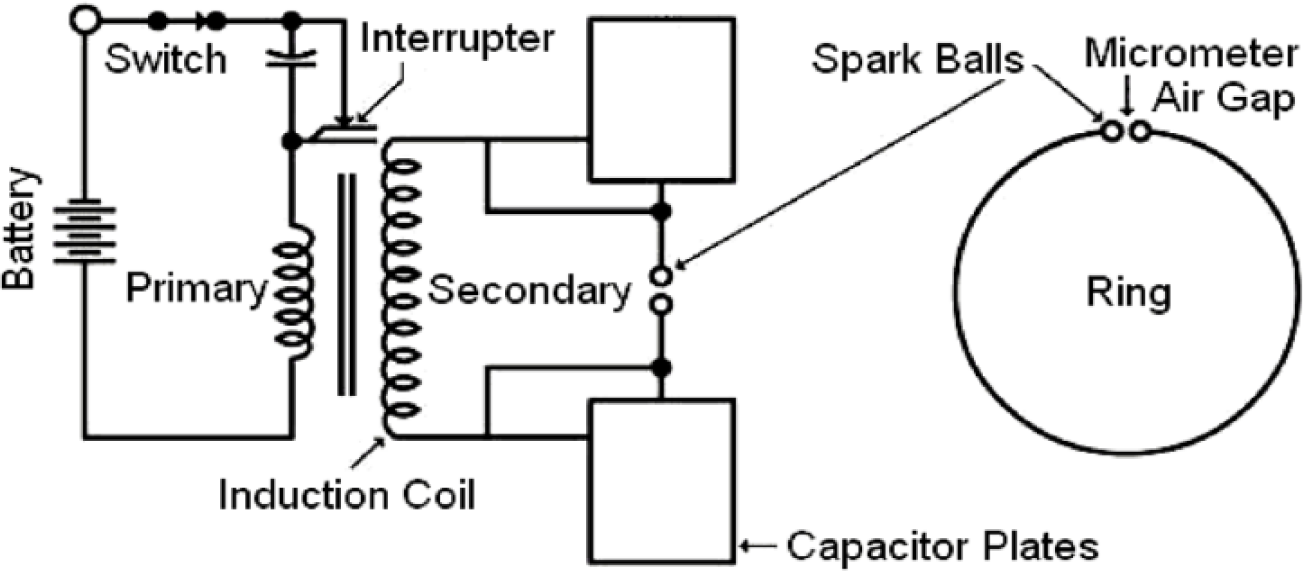
Hertz’s Spark Gaps for Transmitter (Left) and Receiver (Right).
An English physician, Sir Oliver J. Lodge, using the ideas of previous inventors, realised that the EM resonator was very insensitive and because of this phenomenon he invented a ‘coherer’. In fact, a much better coherer was built and devised by a Parisian professor, Edouard Branly, in 1890. He put metal filings (shut in a glass tubule) between two electrodes and as a result a great number of fine contacts were created. This coherer suffered from one disadvantage: it needed to be ‘shaken before use’. Owing to imperceptible electric discharges, it always got ‘baked’ and blocked.
In early 1889, the Russian professor of physics, Aleksandar Stepanovich Popov, conducted experiments along the lines of Hertz’s research and successfully realised the first practical experiments with EM waves for the transmission of radio signals. Soon after, Professor Popov attended a meeting of the Russian Physical and Chemical Society at which Professor N. G. Yegorov, from St. Petersburg, reproduced Hertz’s experiments, but in a manner that Popov felt to be insufficiently graphic. It took him only a few months to build a more compact and effective device to demonstrate Hertz’s experiments, which he then gradually improved, so that by 1894 he had constructed a working transmitter that generated electromagnetic waves based on Hertz’s vibrator using a Ruhmkorff coil. This was the first transmission and reception system for remittent electronic waves suitable for the reliable communication of information in the history of telecommunications. Popov’s brilliant invention became the prototype for the subsequent first generation of radio communication systems. In 1894, Popov built his first radio receiver (Rx) with an improved version of the coherer and successfully demonstrated it in 1895 in St. Petersburg to the Russian Physical and Chemical Society, but he never patented his invention.
In 1895, Popov upgraded the coherer’s sensitivity and invented a special mechanism to automatically re-set the device. In fact, he improved Branly’s radio Rx by the insertion of choke coils on each side of the relay to protect the coherer and by replacing the spark gap with a vertical antenna insulated at its upper end and connected to the ground through the coherer.2,3
Popov then mounted a small bell in a serial connection with the coherer’s relay anchor, whose ringing affected its automatic destabilization and successive unblocked function of the receiver system. On 7 May 1895, he presented a paper to the Russian Physical and Chemical Society concerning a lightning conductor as an antenna, a metal filings coherer and a detector element with a telegraph relay and a bell. Thus, the relay was used to activate the bell, which announced the occurrence of transmitting signals and served as a decoherer (tapper) to prepare the receiver to detect the next signals. This was the first telegraph station in the world, which could work without any wires.
Popov succeeded in making a reliable generator of EM waves, when the detecting systems in common use were still unsatisfactory. So his system was extended to function as a wireless telegraph with a Morse telegraph key attached to the transmitter (Ruhmkorff coil and blocking capacitor). In May 1895, instead of a bell he contrived to use a clock mechanism to realise direct, fast destabilization of metal filings in the coherer upon receipt of the signals. He then succeeded in making a more reliable generator of EM waves, when the receiving (detecting) systems in common use were still inadequate.
Thus, using the inventions of his predecessors and on the basis of scientific experiments, Popov elaborated the construction of the world’s first radio receiver (coherer, amplifier, electric bell, aerial) with a wire-shaped antenna system in the air attached to a balloon, as shown in Figure 2. In December 1895, he officially announced the success of a regular radio connection and on 21 March 1896 he demonstrated it in public at St. Petersburg University. Finally, on 24 May 1896, Popov installed a pencil instead of the bell and sent the first wireless message in the world at a distance of 250 metres between two buildings, conveying the name ‘GENRICH GERZ’ (the name of Hertz in Russian) by Morse code, using his homemade transmitter and receiver.
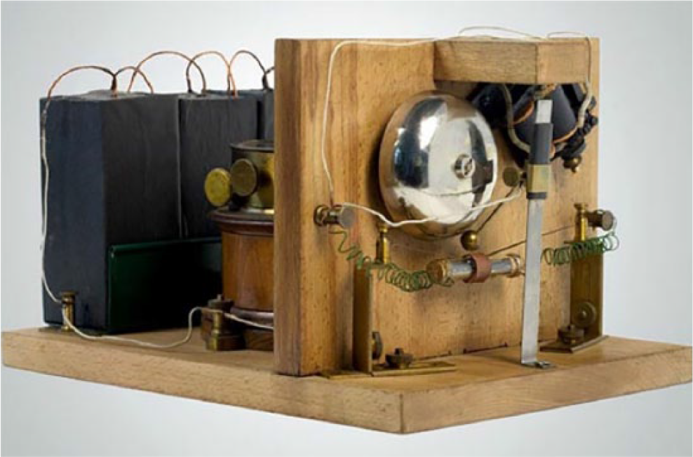
Popov’s Spark Gaps. Copyright © 2018 ITU. Reprinted from ITU News, Issue No. 9, November 2009. Available at: http://www.itu.int/net/itunews/issues/2009/09/57.aspx
In March 1897, Popov equipped a coastal radio station at Kronstadt, and fitted the Russian Navy cruiser Africa with his wireless apparatus. In the summer of 1897, Popov started with experiments at sea, using radios onboard ships. In 1898, he succeeded in relaying information at a distance of 9 km and in 1899, a distance of 45 km between the island of Gogland and the city of Kotka in Finland. With all his inventions, Popov made advances on the discoveries of Hertz and Branly and created the groundwork for the development of the maritime radio.
In 1895, a few months after Popov’s breakthrough, a young Italian experimenter, Guglielmo Marconi, using Popov’s circuit, 5 achieved a radio transmission of several kilometres, becoming the first to put EM theory into a business application. Thus, a detailed report on Marconi’s experiments was presented by the chief of the UK’s engineer telegraph agency V. Pris (1834–1913), who refused to assist Marconi in England (Forum - Yakimenko S). This report shows that Marconi’s transmitter was designed by his Italian teacher A. Rigi and that he used the receiver of Professor Popov. As the report stated: ‘G. Markoni did not do anything new’.1,2,4,5 Unlike Popov, Marconi was not the inventor of the radio, but a good businessman who was able to assemble other people’s work into the commercial product that lay at the heart of his financial and manufacturing empire.
In 1897, Marconi registered the Wireless Telegraph and Signal Company, which then in 1900 was renamed Marconi’s Wireless Telegraph Company, Ltd (MWCT). This company started to design and manufacture radio telegraphs transmitting and receiving equipment with an antenna, other accessories, devices for transmitting distress messages for shipping industries and later for commercial ships to the shore and the vice versa direction at the turn of the twentieth century. In Figure 3 (left), the Marconi of America QMS 1/2 KW Quenched Spark Gap Ship Transmitter in 1919 is shown; in Figure 3 (middle), the Marconi of America Type-I Antenna Switch is illustrated; in Figure 3 (middle below), the Marconi Wireless Keys from 1912 is shown; and Figure 3 (right) shows the Marconi’s Wireless Marine Rx-Tuner Type 226A from 1916.
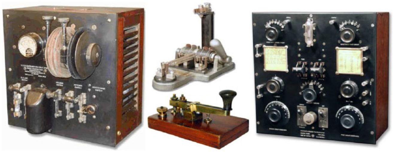
Marconi’s Ship Radio Equipment.
In 1900, R. Fessenden made the first transmission of voice via radio in the USA, Fleming in 1904 discovered the diode valve, while their countryman and pioneer Lee de Forest developed and used a triode valve, which made it possible to use radio not only for radiotelegraphy but for voice communications. As early as 1907, De Forest had installed a triode valve mobile radio on a ferry operating on the Hudson River near New York City.
Development of maritime radiocommunications
The very impressive development of mobile radio for maritime use, and later on for aero applications, initiated a mobile distress and a safety radio. With further innovations an age-old barrier between ships and shore was eliminated and the capacity to communicate with onboard mobile radios independent of space and time was created. These early radio devices were primitive by today’s standards, incorporating spark transmitters, which blasted their signals across almost the entire radio spectrum. It is supposed that the first vessel to have a Ship Radio Station (SRS) was the American liner St. Paul, equipped in 1899. The next, early in the following year, was the German vessel SS Kaiser Wilhelm der Grosse.
Thereafter, the mobile radio spread rapidly throughout the shipping and safety business. In 1899, A.S. Popov was the first to successfully demonstrate mobile wireless telegraphy communications at a distance of twenty miles between warships of the Black Sea fleet. Arriving in Sevastopol with P. N. Rybkin and other participants in the radio project, Popov tested three ‘Popov-Ducretet’ radio stations mounted on three Russian military ships. The news of Marconi’s work, as disclosed in his patent of June 1896, stirred Popov to undertake fresh activity. Working in conjunction with the Russian navy, he affected the ship-to-shore communication over a distance of 10 km (6 miles) by 1898. The distance increased to about 50 km (30 miles) by the end of the following year, by which time he had also visited wireless stations in operation in France and Germany.1,2,6
In October 1899, the Chief Commander of the Black Sea Fleet, Vice-admiral S. P. Tyrtov sent a Statement of Commission regarding wireless telegraph testing using Popov’s technique. The first recorded use of radio for saving life at sea occurred early in March 1899. The lightship on the Goodwin Sands, near Dover on the south coast of England, was fitted with one of the first seaborne Marconi SRS and used it to report to the Coastal Radio Station (CRS) that the German steamer Elbe had run aground. The first distress signal CQD (Come Quick Distress) was used from 1904 on British ships equipped with Marconi radio devices. After the collision of two passenger ships, the British SS Republic and the Italian SS Florida, running in thick fog in the early hours of 23 January 1909, the radio officer on board the Republic sent the first distress signal: ‘CQD MKC (call sign of Republic), CQD MKC, CQD MKC’, and text: ‘Republic rammed by unknown steamship, 26 miles southwest of Nantucket, badly in need of assistance’.
After the catastrophe of the Titanic in the early hours of 15 April 1912, the UK proposal for a distress signal was the already established CQD, the USA proposed the NC of International signal codex for distress and Germany proposed its own SOE, which was already in use on German ships as a general inquiry signal similar to CQ (call). The signal CQ was then used only by the Marconi system, while the British wanted to stick to the Marconi signal CQD. Figure 4 (left) shows Marconi’s ship radio station used on board the Titanic. Two men employed by the Marconi Company worked as radio officers in this small windowless room near the bridge. Their main job was to receive and send messages by radio waves using Morse code. Little did they know they would soon be tapping out one of the first SOS signals from a ship in distress. However, after the Titanic disaster, new radio regulations and recommendations required more effective radio communication equipment and unique distress signals and rescue procedures. The prototype of more reliable ship radio stations used since 1940 is illustrated in Figure 4 (right).

Marconi’s Ships Radio Stations.
By 1912, there were 327 established CRS and 1,924 SRS available for public, commercial and safety uses. The use of the radio at sea became more or less indispensable, creating an immediate need for enforcement of the rules and regulations under international radio coordination. Accordingly, the first Preliminary Radio Conference was held in Berlin in 1903, where some of the basic principles for the use of radiotelegraphy at sea were established. In the subsequent Berlin Conference of 1906, two radio frequencies, 500 and 1000 kHz were earmarked for radio distress correspondence. This conference also established a standard for international distress signals in radiotelegraphy, SOS, which is still in use.
The radiotelephony distress signal MAYDAY was adopted in 1927 at Hanover. Its name derives from the French phrase ‘m’aidez, which transaltes as ‘help me’ in English. The first international SOLAS (Safety of Life at Sea) Convention was held in 1914 in London, partly as a result of the Titanic disaster. It stipulated Morse telegraphy radio on 500 kHz and the auxiliary battery-operated backup radio transceiver unit on 500 kHz as well. In addition, ships carrying more than 50 passengers were required to carry radio devices with a range of at least 100 nautical miles, with larger ships having to maintain continuous radio watch with a minimum of three radio officers.
At the conference in Washington in 1927, supplementary regulations established separate safety calls in radiotelegraphy for distress, urgency and security —SOS, XXX and TTT, respectively. These three signals were obligatory only on 500 kHz, with a silence period of three minutes after every 15th and 45th minute. The use of radiotelephony at sea was also introduced at that time, followed soon after by the first radiotelephone communications between SS America and the coastal radio station at Deal Beach, New Jersey. Then, at the radio conference in Madrid, radio station call signs and radio frequencies were determined, while the International Telecommunications Union (ITU), with its head office in Geneva, was established, and radio regulations (RR) were adopted. At the conference in Atlantic City in 1947, a supplementary ITU RR was adopted and a new radiotelephony distress frequency on 2,182 kHz was accepted, instead of the old one on 1,650 kHz, with silence periods of 3 minutes after every 00th and 30th minute.
Three telephone safety calls were previously used for distress, urgency and security such as: MAYDAY, PANPAN and SECURITE, respectively, on 2,182 kHz and more recently, on 156.8 MHz (16 VHF channel). Finally, the new era of transistors commenced, with revolutionary integrated circuits introduced from 1957 onwards. In the meantime, there was a change to amplitude modulation with a new automatic repeat request (ARQ) system for use in maritime radio telex services. Otherwise, the ARQ protocol was used for error control in data transmission; namely when the receiver detects an error in a packet, it automatically requests the transmitter to resend the packet.1,7,8,9
Conclusions
Maritime mobile radio communication networks are very important systems and platforms for providing successfully commercial and safety radio communications for merchant shipping. The rapid alert, transmission and reception of distress messages via ship radio stations or other distress equipment is vital to safety at sea. It is essential that warnings be given to ships on matters that can affect their safety. These include all new developments of the establishment modern radio solutions and regulations resulting in the adoption of the International Convention for the Safety of Life at Sea (SOLAS) of the International Maritime Organization (IMO). In this effort, the IMO developed an integrated system of radio and satellite communications known as the Global Maritime Distress and Safety System (GMDSS), which provides an enhanced commercial and distress service at sea. This was not due to Marconi, who was a businessman rather than an inventor, but to Professor Popov, who on a scientific basis used the discoveries of his predecessors and his own research innovations to demonstrate the first mobile radio transmission in the world.
Footnotes
1.
D. St. Ilcev, Global Mobile Satellite Communications for Maritime, Land and Aeronautical Applications (Springer, Boston, 2005).
2.
Ю. И. Панин, ‘Морская радиосвязь’, Транспорт, Ленинград (1985).
3.
D. P. Stern, ‘All Things Electric and Magnetic’, Stargazers, NASA (Washington, DC, 2010).
4.
E. Schimana, ‘Popov System’, Institut für Medienarchäologie (IMA) (St. Pölten, Austria, 2017).
5.
J.F. Wollert & W. Gebhardt, The Wireless Book – Evolution and Communications (Westfalia-Druckerei, Lohne, Germany, 2010).
6.
J. Jenkins, ‘Vintage Radio and Security Apparatus’, American Museum of Radio and Electronics (Bellingham, Washington, 2017).
7.
S. Goncalves, ‘Marconi and the Birth of Wireless’, Sarah G-WDD (Long Island, NY 2017).
8.
SMM, ‘1940’s Marine Radio Room’, Sandford Mill Museum, Chelmsford, England, 2017.
9.
B. Samuelsson, ‘Radio Collection’ (Oslo, Sweden, 2017).