



Abstract
Background
In recent years, the importance of chemical experiments has increased, and the frequency of chemical experiments has also increased. As the frequency of chemical experiments increases, the number of chemical experiment-related accidents increases proportionally.
Objective
Accordingly, we design a remote control biomimetic robotic arm that can safely and actively handle hazardous chemicals on behalf of human to reduce human casualties caused by chemical experiment accidents without compromising the autonomy of experimentation.
Methods
This biomimetic robotic arm can identically mimic the operator arm's movement. The robotic arm moves with 6 degrees of freedom (DOF). The inertial measurement unit (IMU) sensor we designed ourselves is based on micro-electromechanical system (MEMS) technology, and in the IMU sensor the accelerometer-gyroscope sensor and the wireless communication module are integrated. This IMU sensor calculates its own instantaneous angle on a particular axis. The micro controller unit (MCU) controls motor using the angle data of the IMU sensor so that the robotic arm moves in the same movement as the operator arm to which the IMU sensor is attached.
Results
Three IMU sensors were attached to the operator's upper body, upper arm, and lower arm, enabling the robotic arm to accurately replicate the operator's movements. Performance evaluation through comparative experiments confirmed that the robotic arm closely tracked the operator's joint motion and overall trajectory. Although a time delay of approximately 1.4 s was observed due to communication and processing latency, the system maintained stable performance under various motion and load conditions, with joint angle errors remaining below 5.2%.
Conclusion
The proposed system enables biomimetic motion of a robotic arm using IMU-based sensing and wireless control, allowing hazardous chemicals to be handled safely during chemical experiments.
Introduction
Nowadays, chemical experiments are effective and essential for research and learning in various fields of chemistry. However, accidents such as burns, frostbite, and explosions caused by human error and hazardous chemical leakage and mixing tend to increase in dealing with hazardous chemicals.1–3 In addition, such accidents can pose a great risk to the safety of the experimenter. For this reason, in order to prevent the safety of experimenters from accidents of chemical experiments dealing with hazardous chemicals, the number of cases of automated robotic arms conducting chemical experiments on behalf of experimenters has increased recently.
However, the conventional chemical experiment robotic arms currently used in the laboratory are automated passive robotic arms. The automated passive robotic arms detect and estimate the position of objects, contents in the workspace, and the next task process by measuring the weight of objects, recognizing coded markers, or using a camera sensor.4–6 These passive robotic arms are commonly operated repeatedly by only predetermined algorithms. Additionally, these passive robotic arms are designed to recognize only learned objects. Thus, since these passive robotic arms can only move passively, it is difficult to respond to unexpected situations in real time during chemical experiments dealing with hazardous chemicals, and only experiments with a standardized work process are possible, while creative and challenging experiments are not.
Recent advances in robotic control methods provide potential solutions to address these limitations. For example, the paper “Task Space Robotic Manipulation Based on Revised Virtual Decomposition Plus PD Control” introduces a robust control framework that combines revised virtual decomposition control with proportional-derivative (PD) control to enhance the precision and adaptability of robotic systems. 7 This approach allows robotic manipulators to perform task-space operations with increased stability and flexibility, enabling real-time adjustments to dynamic and unpredictable environments. Integrating such advanced control methodologies into biomimetic robotic arms could significantly improve their performance in hazardous chemical experiments, making them more capable of handling unforeseen challenges while maintaining operator safety.
To enable creative and challenging experiments while ensuring the safety of experimenters in chemical experiments dealing with hazardous chemicals, a remote-controlled chemical experiment robotic arm that can identically mimic the movement of the operator arm was developed and designed to biomimic the human arm. Figure 1 and Table 1 show the overall structure and composition of parts of this robotic arm. Since this robotic arm operates in the same movement as the operator arm in real time, it can be moved as the operator wants. And the operator remotely controls the robotic arm while monitoring the experimental process directly in a safe space separated from the experimental space where the robotic arm operates. Accordingly immediate feedback is possible when a problem is found in the existing experimental process during a chemical experiment. Moreover, dangerous situations can be quickly dealt with, errors in experimental results can be reduced, and the productivity of experimental research results can be improved while ensuring the safety of the experimenter.
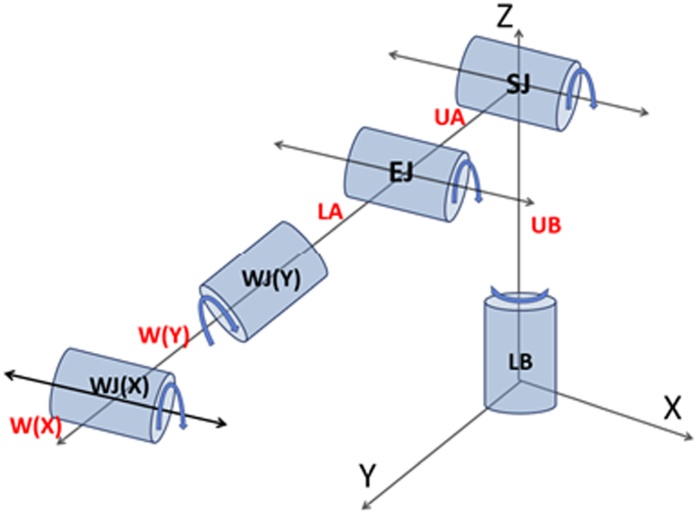
Kinematic diagram of robotic arm.
Descriptions about Parts of Robotic Arm and Operator Arm

Design of biomimetic robotic arm
We designed the robotic arm to mimic the operator's arm movement identically, providing high activity and freedom for safely handling hazardous chemicals. A critical design choice was to place the SJ at the top of the robotic arm, followed by the EJ and WJ in order below it, to align with the musculoskeletal arrangement of the human arm, as shown in Figure 2, unlike conventional robotic arm designs where the SJ is positioned at the base to reduce instability caused by the center of gravity.4,8–10 This biomimetic design decision was driven by the need to achieve both structural and functional similarity to the human arm to maximize operational precision and versatility.

Biomimetic design of robotic arm.
This biomimetic approach allows the robotic arm to replicate natural human arm movements more effectively, thereby improving control accuracy and intuitiveness during operations. According to the paper “Development and Characteristics of a Highly Biomimetic Robotic Shoulder Inspired by Musculoskeletal Mechanical Intelligence,” adopting a biomimetic structure can significantly improve the safety and reliability of robotic systems, especially in dynamic and hazardous environments. 11 The natural movement dynamics afforded by this structure minimize abrupt motions that could lead to accidents, particularly in handling volatile materials.
This biomimetic approach offers notable advantages in safety and versatility when dealing with hazardous chemicals. As emphasized in “Autonomous Biomimetic Solid Dispensing Using a Dual-Arm Robotic Manipulator” biomimetic designs improve safety by enabling robotic arms to operate more effectively in controlled environments, minimizing human exposure to hazardous conditions. 5 By accurately mimicking human movements, the robotic arm can perform delicate operations in a manner that reduces the risk of spillage, contamination, or accidents. Moreover, the biomimetic design ensures greater versatility, allowing the robotic arm to adapt to a wide range of tasks and environments. Unlike conventional designs that may limit operational flexibility due to stability constraints, the top-mounted shoulder configuration supports more complex and diverse maneuvers, enhancing the robotic arm's application scope in both laboratory and industrial settings.
The three IMU sensors that control the robotic arm LB, SJ, and EJ are attached to the human arm UB, UA, and LA, respectively. Two motors were installed on the robotic arm WJ to enable rotation on the X and Y axes. The WJ(X), WJ(Y) and GJ are operated by the servomotor, and the servo motor is controlled by a Bluetooth app. The robotic arm has only six rotational degrees of freedom. The frame of the robotic arm was made through 3D printing using a lightweight and cost-effective PLA material. The length of the robotic arm UB, UA, LA, and W(Y) are designed to be 230 mm, 220 mm, 190 mm, and 45 mm, respectively. To reduce the weight of the robotic arm, UA and LA are designed with a truss structure.
Control algorithm
A pair of IMU sensors communicate wirelessly with each other on a one-to-one basis. Each sensor is called ‘Slave’ and ‘Master’ and plays a different role. Slave detects its own acceleration and angular velocity values on the 3-axis and calculates filtered angle value on a specific axis from them. Then the slave sends this angle value to the Master through BLE. Master receives the angle value sent by Slave through BLE.
Figure 3 shows the flow in which data about the operator arm passes through Slave, Master, and MCU to become data to drive the motor. When the operator arm moves, the operator arm UB, UA, and LA naturally also move. Slave1, Slave2, and Slave3 are attached to the operator arm UB, UA, and LA, respectively, so Slave1, Slave2, and Slave3 measure and collect instantaneous angular velocity (

Robotic arm control algorithm.
In the MCU, the angular displacement of the operator arm for 1 s (
In order to ensure that the angular displacement of the robotic arm for 1 s is equal to the angular displacement of the operator arm for 1 s, the angular displacement of the Motors for 1 s (
In order for the robotic arm to move in the same movement as the operator arm, it is necessary to measure the instantaneous angle of the operator arm. Accordingly, we decided to use an inertial measurement unit (IMU) that can detect instantaneous acceleration and instantaneous angular velocity values on the 3-axis. 12 This is because the instantaneous angle on a specific axis can be calculated from the instantaneous acceleration and the instantaneous angular velocity on the 3-axis. In addition, since the robotic arm must be remotely controlled and operated uninterrupted, the IMU sensor was developed by ourselves so that it can communicate wirelessly and can be used semi-permanently without the need to replace the battery by using the secondary battery. Figure 4 is the internal structure of the IMU sensor. The internal structure of the IMU sensor representatively consists of a MPU-6050, which detects acceleration and angular velocity on the 3-axis, a ESP32 WROOM 32D, which enables wireless communication between IMU sensors with Bluetooth Low Energy, a Lithium Polymer Battery, which is a secondary battery as the sensor's external voltage supplier, and a low drop out (LDO) voltage regulator that makes and supplies 3.3 V to internal circuits.

Structure of IMU sensor.
Within the MPU-6050 of the IMU sensor, gyroscope and accelerometer measure instantaneous angular velocity (
However, 
However, even in this case, there is a problem that a large error occurs when a large force is applied to the sensor. Accordingly in this case, the high-band frequency range is severely damaged. In other words, gyroscope and accelerometer have errors of opposite characteristics when calculating
The complementary filter is a method for correcting sensor data by combining the strengths of a gyroscope and an accelerometer. The gyroscope accurately measures high-frequency signals (rapid motion changes) but has the disadvantage of accumulating drift over time, which leads to inaccuracies in the long term. On the other hand, the accelerometer reliably measures low-frequency signals (gravity-based orientation information) but is sensitive to external vibrations or short-term changes in acceleration, making it prone to noise. The complementary filter compensates for these shortcomings by processing the two-sensor data separately based on their frequency ranges. It uses the gyroscope data in the high-frequency range and the accelerometer data in the low-frequency range. This approach allows the gyroscope's drift to be corrected by the accelerometer's long-term stability, and the accelerometer's short-term noise to be mitigated by the gyroscope's fast responsiveness. As a result, by combining the data from these two sensors using a complementary filter, it becomes possible to achieve a more accurate and stable angle of IMU sensor than when using the sensors independently. Additionally, to ensure greater accuracy and reliability of the angle data, the filter's weight for the gyroscope and accelerometer was experimentally optimized. These approaches effectively mitigated drift and enhanced long-term angle accuracy compared to using sensors independently, resulting in greater control stability.
Figure 5 shows a Complementary filtering process in which the low-band frequency range of the rotation angle on the X-axis passed through the Complementary filter (


Complementary filtering process.
Where,
The rotation angle on the Z-axis of the IMU sensor is obtained from gyroscope, so the rotation angle on the Z-axis of the IMU sensor is equal to the rotation angle on the Z-axis calculated from gyroscope (
However, the angle obtained from the gyroscope has a problem that small errors are accumulated little by little. Hence, if improvement is made in the future, an IMU sensor integrated with a magnetometer will be developed and the exact rotation angle on the Z-axis will be implemented. 15
Consequently, the instantaneous angle of the operator arm UB (
Performance analysis of the robotic arm joint
To analyze the performance of the robotic arm joints, angle data of the robotic arm UB, UA, and LA are required. For that reason, in the following performance analysis experiments of the robotic arm joint, the instantaneous angle of the robotic arm UB, UA, and LA moving along the operator arm are measured by attaching the IMU sensor to the robotic arm UB, UA, and LA.
Figure 6(a) shows the performance of the robotic arm LB by comparing the instantaneous angle of the operator arm UB and robotic arm UB. Figure 6(b) shows the performance of the robotic arm SJ by comparing the instantaneous angle of the operator arm UA and robotic arm UA. Figure 6(c) shows the performance of the robotic arm EJ by comparing the instantaneous angle of the operator arm LA and robotic arm LA. In these figures, experiments are carried out without the load that the robotic arm G holds, and the angle of operator arm and robotic arm were measured every second for 1 min. In Figure 6(c), the operator arm UA is fixed and only LA rotates. In these Figures, the average time delay between the robotic arm and the operator arm is 1.4 s. This time delay occurs because Slave sends angle data to the Master every second, and it takes some time for the Master and MCU to process the received data. The mean percentage error (MPE) between the angle of the operator arm and the angle of the robotic arm after 1.4 s, which is the time delay, is 5.2% in Figure 6(a), 2.9% in Figure 6(b), and 3.5% in Figure 6(c). The robotic arm SJ and EJ showed high accuracy and precision with low error, but the robotic arm LB showed low accuracy and precision as the errors accumulated.
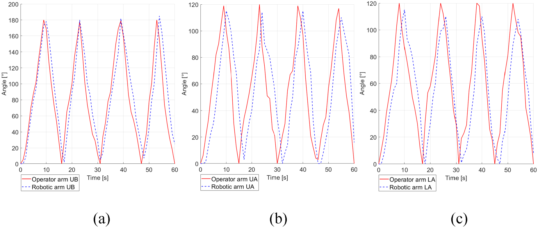
Performance analysis of the robotic arm: (a) LB; (b) SJ; and (c) EJ.
The implications of these results are critical for real-time operation, especially in hazardous environments. The average time delay of 1.4 s can pose a significant challenge in scenarios requiring immediate corrective actions, such as handling reactive chemicals or mitigating potential accidents. For instance, even a minor delay could result in the spillage of hazardous materials or the failure to neutralize a chemical reaction in a timely manner. The relatively higher error accumulation in the LB could compromise the robotic arm's ability to maintain stable positioning and alignment, which is vital for precise manipulations like transferring liquid between containers or positioning delicate apparatus.
Figure 7 shows result of the performance analysis experiment of the robotic arm EJ under various loading conditions. In this experiment, the angle of the robotic arm LA is measured, when the robotic arm G holds various masses (from 35 to 80 grams). 16 Also, the operator arm LA was set to be lifted to 50 degrees and maintained at 40 degrees from the angular position at which the robotic arm G picked up the mass. As shown in Figure 7, the robotic arm EJ can stably lift the mass up to 75 g, and it is difficult to lift it from 80 g.

Performance analysis of the robotic arm EJ under various loading conditions.
The ability to handle loads of up to 75 g indicates that the robotic arm is suitable for handling lightweight experimental tools and small quantities of chemicals. However, the limitations beyond this point highlight potential safety risks when dealing with heavier equipment or substances. For example, failure to securely grasp and maneuver heavier objects could result in dropped materials, increasing the risk of contamination or exposure to hazardous substances.
A trajectory tracking experiment is performed to measure the trajectory of the operator arm and the trajectory of the robotic arm moving along the operator arm as shown in Figure 8. In this experiment, the trajectory is estimated by measuring coordinates on the X, Y, Z-axis of the operator arm and the robotic arm. The coordinate of the operator arm was measured based on the tip of the operator hand, and the coordinate of the robotic arm were measured based on the tip of the robotic arm G. The coordinates on the X and Y planes of the operator arm and the robotic arm were expressed on a semicircular protractor, and the coordinates on the Z-axis were expressed on a rectangle as shown in Figure 8. In this experiment, the average time delay between the operator arm and the robotic arm is 1.43 s. The mean error (ME) between the robotic arm and the operator arm on the X-axis is 3.5 cm. This is caused by the accumulation of integral errors in the robotic arm LB. The ME on the Y-axis and the Z-axis are 2.5 cm and 2.8 cm, respectively. This occurs because the length of the robotic arm was designed to be shorter than the average arm length of an adult male, considering the instability of the center of gravity.

Trajectory tracking experiment.
The errors observed in trajectory tracking experiments are significant for real-time hazardous operations. For tasks that require precise spatial coordination, such as assembling components or maneuvering around obstacles, deviations of several centimeters could result in collisions or improper assembly. The time delay further exacerbates these challenges, reducing the robotic arm's ability to respond to dynamic changes in the environment.
The performance analysis experiment of the robotic arm joint and trajectory tracking experiment show that the robotic arm we designed can mimic the movement of the operator arm very similarly. However, errors and noise in rotation on the Z-axis of the robotic arm must be resolved, since the drift phenomenon of the gyroscope in which the error of the robotic arm LB is accumulated over time occurs. It is considered that this problem can be solved if the IMU sensor is designed with the magnetometer integrated in the IMU sensor. This integration would significantly enhance Z-axis angular accuracy and reliability by providing absolute orientation measurements calculated from Earth's magnetic field measurements measured by magnetometer and correcting drift of gyroscope, improving overall system precision and robustness. Performance analysis experiment of the robotic arm EJ under various loading conditions shows that the robotic arm can handle plastic experimental equipment and low concentration materials well. However, it cannot handle glass experiment equipment and high concentration materials. Accordingly, it is possible to increase the controllable load by using stainless steel gear and chain with strong tension rather than plastic gear and chain. To further reduce the time delay between the operator arm and the robotic arm, there is a way to reduce the time interval for transferring data from the Slave to the Master (currently 1 s). In this case, the time delay could be significantly reduced. However, the shorter the time interval for transmitting data, the shorter the time to process data. Furthermore, because of the limitations of data processing performance, the shorter the time to process data, the greater the probability of errors in data processing, causing more unstable and inaccurate motor's movement. Accordingly, it is considered that this problem can be solved by using better performing MCU. If an MCU with better data processing performance is used, the probability of errors in data processing even in a short data processing time decreases. Therefore, it is possible to reduce the time delay between the operator arm and the robotic arm while securing stable and accurate movement of the motor.
By complementing these limitations, the robotic arm can handle hazardous chemicals very accurately and precisely with minimal error in the chemical experiment space and respond in real time to unexpected events. Therefore, it is possible to perform various creative and challenging experiments while ensuring the safety of the experimenter by using the robotic arm. Moreover, these enhancements, including the integration of a magnetometer and the use of material of high stiffness and superior MCUs, can expand the scope of applications for the robotic arm beyond chemical experiments. The increased precision, reliability, and load-handling capability make it adaptable for fields such as medical surgery, industrial automation, and disaster response, where remote operation and safety are critical. Consequently, the improved robotic arm system promises to not only enhance the safety and efficiency of chemical experimentation but also broaden the impact of this technology to new, innovative domains.
Footnotes
Ethical approval
This study did not involve human participants or animals, and therefore ethical approval was not required.
Author contribution
Conceptualization, T. Kim, G. Do, I. Kwon, J. Kim and J. Ko; Methodology, T. Kim and G. Do; Software, T. Kim, G. Do, and I. Kwon; Validation, T. Kim, J. Kim and J. Ko; Formal Analysis, T. Kim, G. Do, I. Kwon, J. Kim and J. Ko; Investigation, T. Kim and G. Do; Resources, J. Ko; Data Curation, T. Kim and G. Do; Writing - preparation of the original draft, T. Kim, G. Do, and I. Kwon; Writing - reviewing and editing, J. Kim and J. Ko; Visualization, T. Kim and G. Do; Supervision, J. Kim and J. Ko; Project Management, J. Ko; Funding, J. Ko.
Funding
This research was funded by the Ministry of SMEs and Startups (MSS), Republic of Korea, through the Didimdol R&D Program. (RS-2025-16070997)
Declaration of conflicting interests
The authors declared no potential conflicts of interest with respect to the research, authorship, and/or publication of this article.
Data Availability Statement
The data supporting the findings of this study are available from the corresponding author upon reasonable request.