
Abstract
In this paper, the thread turning of aluminum 7075-T6 alloy is studied using micro-hole textured solid-lubricant embedded carbide inserts. The primary focus of this work is to enhance the performance of the thread turning process for producing high quality threaded parts. To achieve this, micro-holes were generated by laser micro-machining on the rake face of tools and then, MoS2 and CNT (carbon nanotube) solid-lubricants were embedded into micro-holes. The effects of micro-holes and solid-lubrication on the performance of the thread turning process were examined using traditional tool (T0), micro-hole textured tool (T1), micro-hole textured MoS2 embedded tool (T2), and micro-hole textured CNT embedded tool (T3). In this study, cutting forces, chip-tool contact length, built-up edge (BUE), surface roughness, and operating cost were investigated. The influence of micro-hole generation on the mechanical strength of cutting inserts was evaluated using the finite element method. The results showed that the fabrication of the micro-holes on the rake surface of cutting inserts has no significant effect on the mechanical strength of the tools. The comparisons of our method with traditional tools demonstrated that the cutting performance improved in the threading process. Our results reveal that the main cutting force, radial thrust force, surface roughness, built-up edge, and chip-tool contact length reduced 37.1%, 40.9%, 37.9%, 58.3%, and 38.2%, respectively, as T3 tools are applied in this process. A cost analysis, based on estimated tooling costs, showed that the T3 tool can yield an 18% reduction in overall operating cost.
Introduction
Threaded parts production is one of the basic importance of manufacturing engineering since every equipment has some threaded parts. Threaded parts are generally used as power or motion transporter, fasteners, and for adjustment. Besides, internal and external threads are produced by thread cutting and metal forming. 1 Threads manufactured by metal forming have greater strength than the machined ones, but they could not guarantee high precision similar to thread cutting. Especially, they are not appropriate for brittle materials that cannot be produced through plastic processes. Surface quality and precision of threads are of special importance in applications such as machine tools because any dimensional or form errors affect the accuracy of the machine. Thread turning is the common cutting process for external thread generation. 2 Since thread turning is a form cutting operation, a long section of the cutting edge is engaged in the cutting process, and this results in wide chips and large cutting forces that lead to high temperature as well as tool wear. 1 So, efficient cutting conditions are necessary for the manufacturing of high-quality threaded parts.
High cutting forces and temperature during the machining of high strength materials leads to extreme tool wear. Several research works have been made to reduce the cutting force and temperature at the chip-tool interface by the use of cutting fluids.3,4 Because of the low penetration of coolant and lubrication into the chip-tool interface, the efficiency of these cutting fluids reduces in severely machining conditions. On the other hand, the cutting fluids contaminate the environment, endanger operators, and wear out machine tools. 5 Although the dry machining processes diminish the mentioned problems, in this procedure the tool life decreases due to the high friction between tool and chip. Several researchers and scholars have tried to eliminate cutting fluids in machining processes by some techniques such as developing new tool materials,6–9 cryogenic machining processes,10,11 minimum quantity lubrication machining, 12 hybrid machining,13,14 and etc. Surface texturing of cutting tools is recognized as another approach for dry machining. Lubrication capacity, friction coefficient, and wear resistance between two sliding surfaces are improved by surface texturing. This technique efficiently provides lubricants to the unreachable areas of the contact zone to reduce friction on the chip-tool interface, decrease contact length, and increase tool life.15–20
Several manufacturing processes have been used to create micro-textures on the mating surfaces such as laser surface texturing (LST), electrochemical surface texturing (ECST), electric discharge texturing (EDT), and electron beam machining (EBM). Among these techniques, laser surface texturing has been used widely to generate micro-textures by researchers.21–27
Several studies were conducted to improve the machinability of materials through the use of textured tools. Three types of micro-texture with various area occupancy were created by Zhang et al. 17 during dry machining of titanium alloy. They were reported that the line-textured tools with area occupancy of 10% resulted in the lowest friction coefficient in comparison with sinusoidal and rhombic micro-grooves. Manikandan et al. 28 examined the influence of three different kinds of tools on the machinability of titanium alloy during the turning process. It was observed that the cross textured tool is more effective in the reduction of coefficient of friction, cutting forces, strain rate, and shear strain. Furthermore, cross textured tool created a curling chip with a low diameter that is more favorable in terms of chip control. Sharma and Pandey 29 studied the effect of hybrid textured tools -generated by ND:YAG laser machining – on the machining of 4340 AISI. Their results showed that by using these textured tools, cutting forces, surface roughness, and chip thickness ratio is reduced. Besides, their analysis presented that saw tooth chip during the cutting process is reduced in comparison with the plane tool. In another work, Obikawa et al. 30 generated four types of texture on the rake surface and coated them with diamond-like carbon or TiN. They reported that parallel and dot type textures are more effective than both perpendicular and pit type textures in the reduction of friction force. Jesudass Thomas and Kalaichelvan 31 conducted a comparative study on the influence of micro-texturing on the HSS cutting tool in turning of mild steel and aluminum alloy. Their reports showed that cutting temperature, cutting forces, and chip-tool contact length significantly reduced when micro-textured tools were applied.
In recent years, solid-lubricants such as MoS2, graphite, CaF2, and WS2 are used in machining to improve the tribological properties of the cutting tools, and they were successfully applied to machining processes in order to reduce cutting forces, friction, and cutting zone temperature.32,33 Wenlong et al. 34 applied MoS2, CaF2, and graphite powders as solid-lubricants in turning of hardened steel. Their studies resulted in the machinability improvement in terms of friction coefficient as well as tool wear. Similar results were obtained in turning of hardened steel with WS2 coated tool by Lian et al. 35 In the other research conducted by Sun et al., 36 MoS2-filled hybrid textured tool was used for turning the pure iron workpiece. According to their results, the cutting performance of the self-lubricated textured tool is improved relative to conventional tools. Another solid-lubricant that has recently received special attention is carbon nanotubes (CNT). CNT has been used to improve the tribological performance of rubbing surfaces.37–39
Although textured tools have been successfully used in turning, milling, and drilling operations, surface textured tools have not been used in the thread turning process. In addition, the performance of CNT as a solid-lubricant was not examined in the machining processes.
In this study, micro-holes were created on the rake surface of cemented carbide inserts using Fiber laser micro-machining. Then, MoS2 and CNT solid-lubricants are embedded into the micro-holes. Thread turning tests on aluminum 7075-T6 alloy were applied with traditional tool (T0), micro-hole textured tool (T1), micro-hole textured MoS2 embedded tool (T2), and micro-hole textured CNT embedded tool (T3). The cutting forces, chip-tool contact length, built-up edge, surface roughness, and operating cost of machined threads were evaluated. The main goal of this paper is to study the performance of textured tools embedded with solid-lubricants in thread turning of aluminum 7075-T6 alloy.
Materials and experimental procedures
The applied experiments in this paper were designed to evaluate the effect of the surface texturing and different solid-lubricants on the performance of the thread turning process. The experimental procedure, threading setup, and measuring tools are described in detail in this section.
In this research, cemented carbide cutting inserts (SECO-CP500) were selected due to its suitability for threading aluminum alloys to perform thread turning experiments. The micro-textures were produced by Fiber laser micro-machining at the rake surface of the tools. In laser micro-machining parameters were wavelength, repetition rate, and scanning speed which were considered 1064 nm, 60 kHz, and 100 mm/s, respectively. In order to generate circular micro-holes on the rake surface, the cutting insert was fixed on a computer-controlled translation table and the laser beam was focused on the rake face perpendicularly. Time duration and pulse energy of laser spots are changed to control the depth of micro-holes. It can be noted that the resolution of the translation table was 0.1 µm. Before the laser micro-machining process, the cutting inserts were cleaned with ethanol. Ultrasonic cleaning was applied to clean the inserts after the laser micro-machining. The rake surface of the cutting inserts was scanned using an AIS2300C type scanning electron microscope. Figure 1 shows the SEM images of developed textured tools and cross-section profile of micro-holes. The micro-holes diameter, depth, and pitch distance are about 70, 13, and 200 µm, respectively. It should be noted that although the laser parameters were set to produce micro-holes with a diameter of 50 µm, the heat-affected zone was obvious which increased their diameters. In this study, MoS2 and CNT powders were used as solid-lubricants to enhance the performance of the cutting process during threading operation. The solid-lubricant was initially dispersed in the acetone through the ultrasonic homogenizer, and then they were applied to the rake surface. Acetone was evaporated, and solid-lubricant was embedded into the micro-holes.
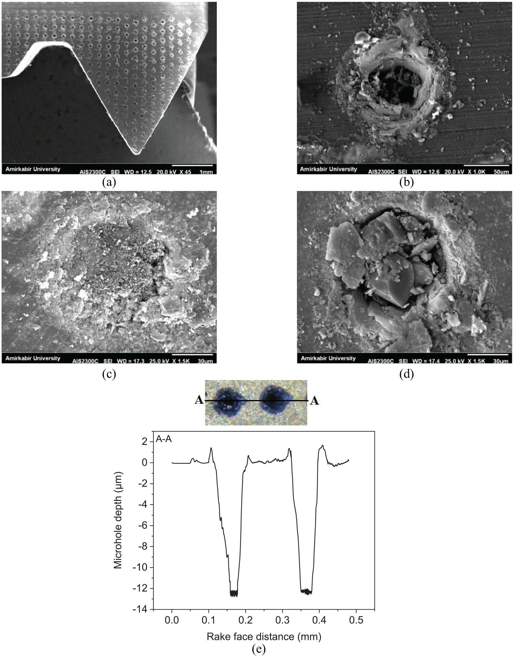
(a) SEM image of the developed textured tool, (b) a single micro-hole, (c) CNT embedded micro-hole, (d) MoS2 embedded micro-hole, and (e) cross-section of micro-holes.
Table 1 shows the properties of different solid-lubricants. The textured tool filled without solid-lubricant is nominated T1, the one embedded with MoS2 is named T2, and the one filled with CNT is nominated T3. The traditional tool has been represented as T0.
Properties of solid-lubricants.

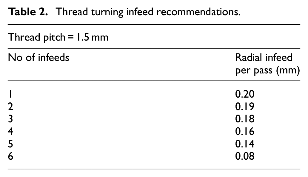
The experimental tests were conducted on the TB50NR Lathe that is able to cut threads with the pitch range of 0.5–40 mm. Cold rolled aluminum 7075-T6 alloy bars with a diameter of 50 mm were used as workpieces. This alloy is a considerably high-strength material used for highly stressed parts such as aircraft fittings, gears and shafts, etc. Moreover, the cemented carbide insert was selected for turning the M48 screw with a 1.5 mm pitch (M48 × 1.5). In addition, the radial infeed method is applied on the workpiece to create the thread form, and depths of cut for different passes are selected according to Sandvik Coromant 40 thread machining recommendations. The number of infeed and radial infeed per pass is given in Table 2. Cutting forces were measured using a Kistler 9121 type dynamometer during each threading pass. The micro-texture pattern and built-up edge (BUE) were examined by utilizing a Dino-lite digital optical microscope. The surface roughness (Ra) of the thread flank face was measured using a TR Profile DH-8 type Trimos profilometer that is able to measure thread flank face roughness. Test conditions for threading experiments are presented in Table 3. The experiments were repeated five times under the same conditions and the mean results were expressed.
Thread turning infeed recommendations.
Test conditions for threading experiments.

Results and discussion
Finite Element Method (FEM) is applied to evaluate the influence of micro-hole textures on the mechanical strength of cutting inserts using ABAQUS software. The material behavior was considered elastic/perfectly-plastic model and the material properties of the cutting insert are given in Table 4. The measured cutting forces in the actual threading process were applied to the chip-tool contact area for the FEM simulations. According to the clamping type of inserts on the tool holder, the bottom surface must be constrained in the y direction. The C3D10M (A 10-node modified quadratic tetrahedron) was chosen as an element type. The element size was 10 µm in the vicinity of micro-holes and cutting edge. The von Mises stress distribution for tools is shown in Figure 2. The results of FEM analysis showed that the fabrication of the micro-holes on the rake surface of inserts has no significant effect on the mechanical strength of the tools. Actual machining tests confirm the results of FEM since insert breakage did not occur.
Material properties of the tools.


Von Mises stress distribution for: (a) traditional and (b) micro-hole textured tools.
Figure 3 shows the main cutting force (Fc) and radial thrust force (Fr) for the four items given in Table 3 based on the experimental results. As revealed in this figure, the cutting forces of each pass are higher than the previous ones because of increasing the engagement of cutting edge in each pass related to the earlier pass. This trend is different in the final pass as the final pass is the finishing pass, which depth of cut is much smaller than others. Besides, it is obvious that both the main cutting force and radial force decreased with the textured tools compared with the traditional tool in all threading passes. In comparison with the traditional tool, the main cutting force and radial force of textured tools reduced up to 19.1% and 19.7%, respectively. Fc and Fr of textured tool embedded with MoS2 reduced up to 28.1% and 30.3%, respectively, while reduction of Fc and Fr for textured tool embedded with CNT is up to 37.1% and 40.9%, respectively.
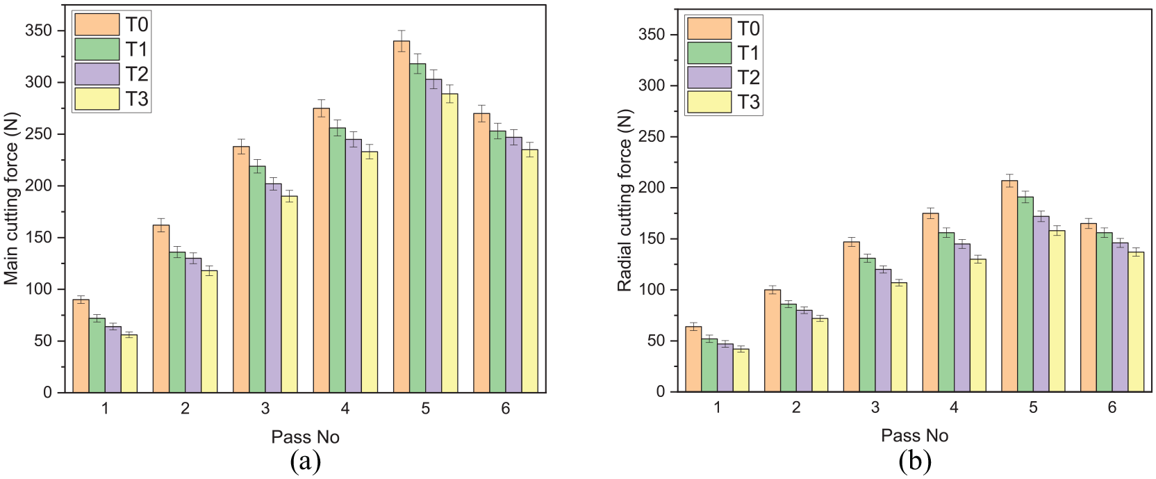
Comparison of experimental cutting forces in each thread turning pass: (a) main cutting force and (b) radial cutting force.
The average friction force (Ff) between the rake surface of the tool and back surface of the chip during cutting operation is calculated by following relation: 28

where Aw is the chip-tool contact area, τc is the shear strength of the chip-tool interface, aw is the chip width, and l is the chip-tool contact length.
The force relations for the thread turning process with the symmetrical triangular insert are obtained from Figure 4:

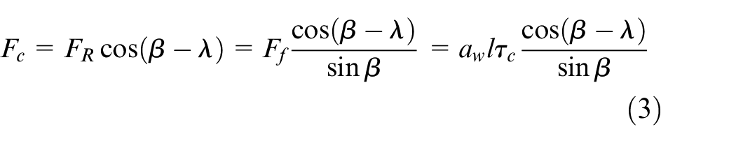
where Fr is the radial thrust force, Fc is the main cutting force, FR is the resultant force, β is the friction angle, λ is the rake angle. It must be noted that no resultant side force acts on the tool since the cutting tool is a symmetrical triangular insert with two cutting edges. 41
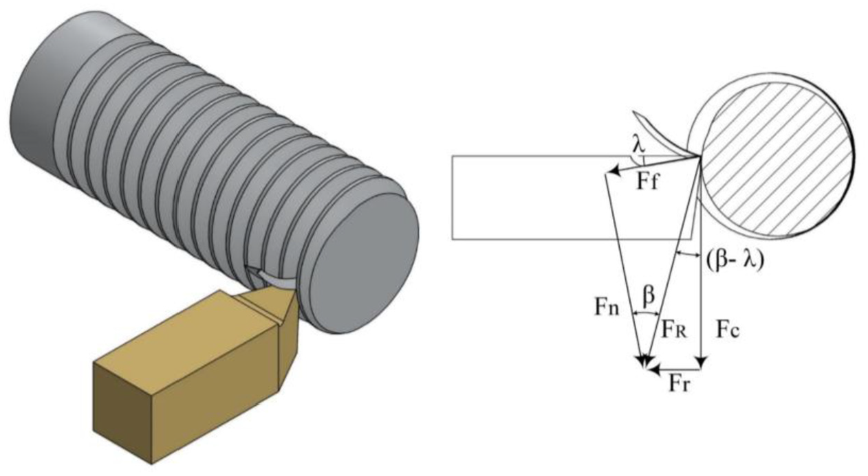
Force diagram of thread turning process.
From the equations (2) and (3), it is observed that the radial thrust force (Fr) and the main cutting force (Fc) are a linear function of the shear strength of the chip-tool interface (τc) and chip-tool contact length (l). Indeed, the creation of micro-holes on the rake surface of the textured tool decreases the effective chip-tool contact area and contact length. The reduction of the force by using the textured tool can be attributed to the reduction of chip-tool contact length. On the other hand, the application of the MoS2 and CNT solid-lubricants in the cutting process can also reduce cutting forces. The shear strength (τc) of both MoS2 and CNT solid-lubricants is much lower than metal shear strength. Therefore, cutting forces during machining with textured tools embedded with solid-lubricant reduce more in comparison with the traditional tool, according to equations (1) to (3).
According to Figure 3, the lubricating performance of CNT solid-lubricant was more efficient than MoS2 solid-lubricant in the force reduction. The main cutting force and radial cutting force of CNT lubricated tool reduced up to 12.5% and 15.2%, respectively, relative to MoS2 lubricated ones. It seems that the difference in microstructure is the main factor that influences the lubricating performance of solid-lubricants. As shown in Figure 5. MoS2 has a lamellar structure, while CNT has a nanotube structure. During machining with the textured tool embedded with MoS2, the microlayers come up from micro-holes and smear between rake surface and chip back, and lubrication can be fully accomplished (Figure 6). The reduction of cutting forces can be attributed to internal sliding between molybdenum disulfide microlayers that have lower shear strength relative to metal shear strength.42,43 However, CNT nanotubes can act as nano-bearing between chip and tool. In fact, the nano-bearing effect that is based on the rolling of carbon nanotubes is an important factor in the reduction of cutting forces. The EDS surface chemical composition analysis (Figure 7) showed that MoS2 (Mo and S elements) and CNT (C element) on the chip back surface of T2 and T3 were identified, which confirmed that the MoS2 and CNT layers were formed between the rake surface and back surface of the chips.

SEM image of: (a) MoS2 (layered structure) and (b) CNT (nanotube structure).

Diagram of chip-tool contact length of solid-lubricant embedded textured tool.
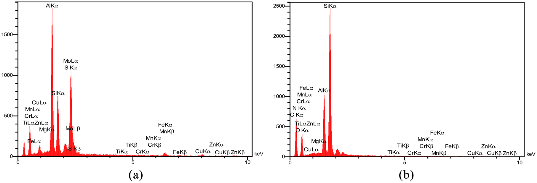
EDS surface chemical composition analysis on the chip back surface for: (a) T2 and (b) T3.
Thus, the reduction in cutting forces has two distinctive causes: the first is the reduction in actual contact length (l) between the rake surface of the tool and chip back, and the second one is the formation of a solid-lubricant layer that reduces shear strength (τc) on the chip-tool interface.
The rake surface of traditional and textured tools is shown after threading tests in Figure 8. It was evident that the chip-tool contact length (l) and harsh chip-tool contact length (lp) on the rake surface of micro-hole textured tools decreased compare with the traditional tool.
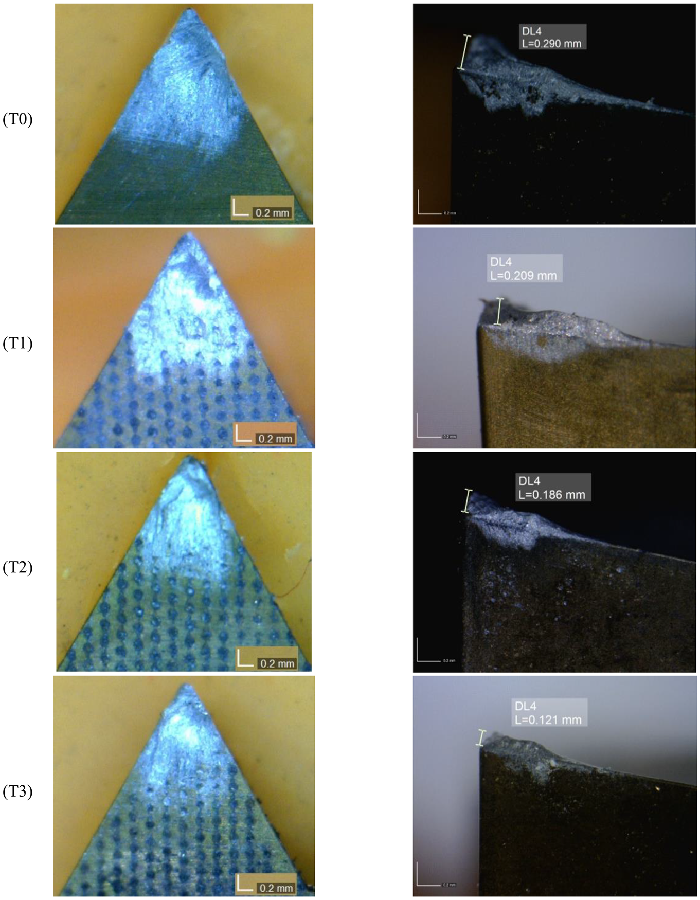
Chip-tool contact area at the rake surface and built-up edge (BUE) for different tools.
Figure 9 shows the EDX analysis of Al weight percent (Wt %) on the rake surfaces after threading tests. The plots in this figure have two sections: the first section shows a high percentage of Al that coincides with the sticking region at the chip-tool interface, and the second one displays a low percentage of Al that corresponds to the sliding contact. According to this figure, the average chip-tool contact length (l) of the T1, T2, and T3 were 1550, 1290, and 1070 µm, respectively, while it was 1730 µm for the traditional tool.

Al weight percent (Wt %) on the rake surfaces of different tools.
Also, the average sticking length (lp) was 1300, 1200, 970, and 770 µm for T0–3 tools. Besides, it is concluded that the average sliding length of T0–3 tools was 430, 350, 320, and 300 µm, which is reduced by 30.2% for the T3 tool in comparison with the T0 traditional one.
It was revealed from Figure 8 that the maximum height and length of the BUE for micro-hole textured tools are lower than the traditional one. The maximum height of BUE for the T0 tool was 0.290 mm, which reduced to 0.209, 0.186, and 0.121 mm for T1, T2, and T3 tools, respectively. This figure confirms that the adhesion of work material on the rake surface decreased using solid-lubricant embedded textured tools. In addition, CNT solid-lubricant is more effective in terms of anti-adhesion property in comparison with MoS2 solid-lubricant. The reduction in l and lp can be one of the reasons for the decrease in cutting forces by using micro-hole textured tools.
Figure 10 shows the optical images of machined threads with the traditional tool and textured tools. Surface roughness measurement of flank faces showed that Ra improved at all micro-hole textured tools. The average Ra of thread produced with the T1, T2, and T3 tools was 2.48, 1.98, and 1.80 µm, respectively, while for a T0 traditional tool was 2.90 µm (Figure 11). The formation of BUE is very significant in thread turning operation due to its effect on the produced surface finish of thread flank faces. As the thread turning process proceeds, BUE gradually grows until it reaches a critical size and then breaks and leaves suddenly with the chip. As shown in Figure 12(a), because of the periodical change in the size of BUE and the tendency of BUE to weld with the machined surface, the roughness of the newly formed surface is increased. This demonstrates the high surface roughness of the flank face of threads machined with the traditional tools. 43 BUE-induced roughness and highly strained areas on the flank face of produced thread with the traditional tool are shown by arrows in Figure 12(b).

Optical images of threaded surfaces machined with: (a) traditional tool, (b) micro-hole textured tool, (c) micro-hole textured MoS2 embedded tool, and (d) micro-hole textured CNT embedded tool.

Surface roughness of threaded surfaces machined with different tools.

(a) Diagrammatic representation of the cutting process showing BUE induced highly strained areas (roughness) on the finished surface 43 and (b) thread flank produced with the traditional tool.
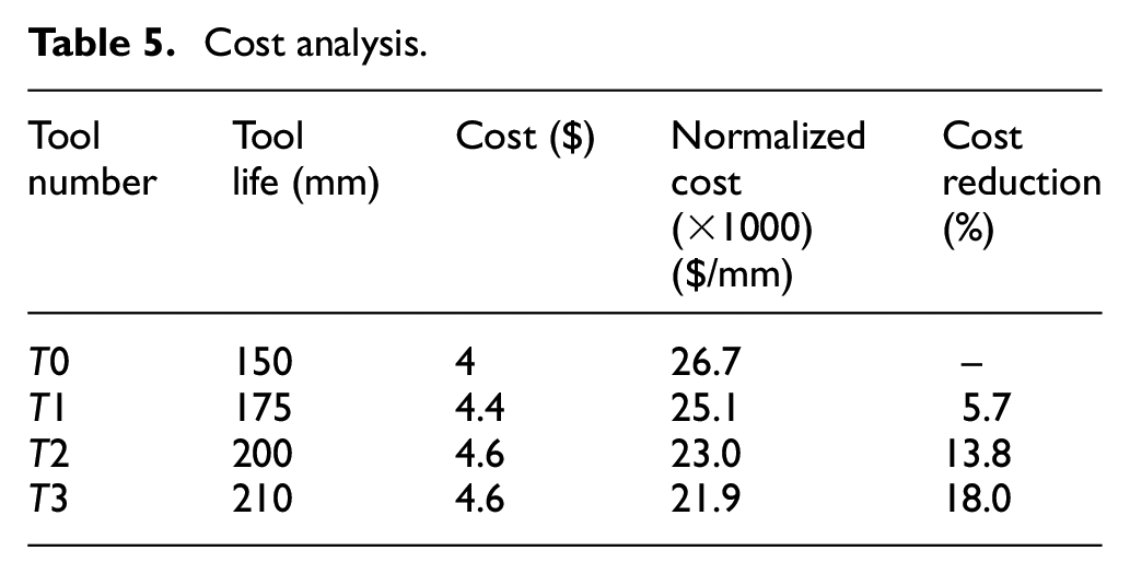
Crater wear, flank wear, surface roughness of machined parts, and cutting forces are the criteria that indicate the tool life and tool failure. Because of the importance of the surface quality of finished products, in this study surface roughness indicator was selected to measure the tool life.44–46 According to ISO 965-1, the tolerance of external thread for the pitch of 1.5 mm and tolerance grade of 4 is 150 µm. Basically, there is a relationship between tolerance and surface roughness of machined products, and tolerance of 150 µm corresponds to surface roughness of 3.75µm. 47 Finally, the Ra of 3.75 µm was selected as a tool life criterion. So, when the Ra of the finished product was higher than 3.75 µm, the tool was failed. Figure 13 presents the tool life of different tools based on produced surface roughness of threaded parts. Results showed that the tool life of T0, T1, T2, and T3 tools was 150, 175, 200, and 210 mm, respectively. In order to predict the cost of the process, several factors have to be taken into account, including the cost of tooling, laser process costs, and solid-lubricant embedding costs. Assumed values for these factors were the tool cost for carbide tool of $4 per insert obtained from the manufacturers cost, laser operation cost of $ 0.4 per insert, and solid-lubricant cost of $ 0.2 per insert. Table 5 presents the cost analysis for different tools. In terms of reducing the tooling cost, the T1, T2, and T3 yielded 5.7%, 13.8%, and 18% reduction in operating cost compared with T0, respectively. In this analysis, the tool change cost was ignored for simplicity. The results indicated that the T2 and T3 tools are both economically advantageous during the threading of aluminum alloy.

Tool life based on surface roughness criterion.
Cost analysis.
Conclusion
In this study, the performance of the thread turning process was examined using traditional tool (T0), micro-hole textured tool (T1), micro-hole textured MoS2 embedded tool (T2), and micro-hole textured CNT embedded tool (T3). The findings of this study are summarized in the following:
The EDS surface chemical composition analysis showed that MoS2 and CNT on the chip back surface of T2 and T3 were identified, which confirmed that the MoS2 and CNT layers were formed between the rake surface and back surface of the chips.
The performance of textured tools in the threading process was more effective than traditional tools. T1, T2, and T3 tools can reduce the main cutting force up to 19.1%, 28.1%, and 37.1%, respectively. Besides, the radial cutting force reduced up to 19.7%, 30.3%, and 40.9% by using T1, T2, and T3 tools, respectively. The reduction of the cutting forces is attributed to the reduction of effective chip-tool contact length and formation of a thin layer of solid-lubricant in the chip-tool interface.
The lubricating performance of CNT solid-lubricant in the radial and main force reduction was more efficient than MoS2 solid-lubricant. In the force reduction comparison between T2 and T3, by using the T3, the main cutting force and radial cutting force reduced up to 12.5% and 15.2%, respectively. Indeed, MoS2 has a lamellar structure, while CNT has a nanotube structure, and this microstructural difference is the main cause that affects the lubricating performance.
The chip-tool contact length of the T2 and T3 is reduced up to 25.4% and 38.2%, respectively. This is because the adhesion of work material on the rake surface decreased through using of solid-lubricant embedded textured tools. Besides, the anti-adhesion property of CNT solid-lubricant is more effective than MoS2 solid-lubricant.
The surface quality of thread flank faces was improved by using micro-hole textured tools. The average Ra reduced up to 14.5%, 31.7%, and 37.9%, respectively, with the T1, T2, and T3. Indeed, the main reason for the high surface roughness achieved by traditional tools is the creation of the BUE-induced strained areas on the flank face of produced threads.
Textured tools were economically advantageous during the threading of aluminum alloy. The T1, T2, and T3 tools reduced overall operating costs by 5.7%, 13.8%, and 18%, respectively, relative to the conventional tool.
Footnotes
Acknowledgements
The authors gratefully acknowledge Roya Shahi for her valuable contributions.
Declaration of conflicting interests
The author(s) declared no potential conflicts of interest with respect to the research, authorship, and/or publication of this article.
Funding
The author(s) received no financial support for the research, authorship, and/or publication of this article.