
Abstract
Tensegrity structures are three-dimensional networks of truss members loaded in tension or compression. The location of the end points of the truss members, denoted as the nodes, and the associated node-member connectivity matrices are the fundamental descriptors in the modeling and design of tensegrity structures. This paper presents systematic analytical formulas for such node locations and connectivity matrices for tensegrity plates of two different topologies. The formulas apply to plates of any thickness, diameter, and complexity. As application examples, dynamic simulations demonstrating a strategy for morphing the planar plates toward domes are studied. The presented formulas allow for efficient computations and can be employed in the numerical analysis and design of shape-controllable antennas and mirrors, architectural constructions, and other applications based on tensegrity plate and dome-like structures.
Introduction
A tensegrity structure is a three-dimensional (3D) network of truss members loaded in tension (denoted as strings or cables) or compression (denoted as bars or struts). The truss members are assumed to be connected through frictionless ball joints, so as to not impose torques among adjacent members. Many studies have shown that by systematically arranging these truss members, one can design structures that provide optimal properties such as minimal mass to support a set of applied forces 1 or absorb and dissipate mechanical energy.2,3 Due to these characteristics, tensegrity structures are being widely studied in civil engineering,4-7 robotics, 8 and aerospace engineering.9,10 In this work, plates and domes formed by the repetition of a tensegrity unit known as the 3 bar prism are studied. Tensegrity structures formed by this prism have been the subject of several studies including form-finding 11 and static and dynamic analyses.12–15 Domes formed by 3 bar prism can be obtained from planar tensegrity plates by shortening the strings on either side of the plate. For example, Chan et al. 16 experimentally demonstrated the ability of a flat tensegrity plate formed by seven prisms to morph toward a dome via string length control. Tensegrity domes 17 have been employed to create satellite reflectors 18 and large civil structures.7,19 In the analysis and design of tensegrity structures, the position of the end points of its truss members, denoted as the nodes, and the associated node-member connectivity matrices are the fundamental descriptors, particularly for topology optimization. Despite the many studies on tensegrity plates in the literature, systematic sets of analytical expressions for the position of their nodes and the node-member connectivity matrices are still not available. Specifying the connectivity matrices is equivalent to characterizing a particular “weave” when making basket, cloth, or net, except that the compressive members involved in the tensegrity “material” allow 3D “fabrics” to be designed. Characterizing the connectivity matrices still does not specify the geometrical shape. To fully define the geometry of a tensegrity structure, the connectivity matrices along with the node locations must be provided.
This work derives analytical formulations for the node positions and connectivity matrices of tensegrity plates with two different topologies. In the first topology, the plates are formed by minimal 3 bar prisms, where “minimal” indicates that the prisms have the minimum of number of strings required to generate a pre-stressable stable structure. The second topology considers plates formed by new 3 bar prisms that include additional members to potentially increase the stiffness in directions that have large compliance in conventional minimal prisms. To form plates, the prisms are arranged in concentric rings, where the number of concentric rings forming the plate is termed as the complexity. The derived analytical expressions for the node positions and connectivity matrices are applicable to plates of any complexity. The Supplemental Material of this article includes MATLAB® scripts that output the derived node positions and connectivity matrices for tensegrity plates given their size parameters and complexity.
Few of the plethora of tensegrities explored in the literature have a common connectivity rule, 20 which makes the task of designing tensegrity structures for specific applications a very challenging task. Among those few tensegrity topologies that posses a common connectivity rule, tensegrity plates are some of the most used in engineering applications as previously mentioned. Analytical formulations for the node positions and connectivity matrices of tensegrity plates would allow for efficient computations and facilitate future research efforts in their analysis and design. Although one can use computer-aided design (CAD) software to create complex topologies through operations such as patterned repetition and mirror, and thus can generate node positions and connectivity matrices for tensegrities, analytical expressions provide the following advantages:
The analytical formulas allow the user to change the shape and topology of the plates by simply changing the value of a handful of scalar parameters such as plate thickness, diameter, and complexity.
The analytical formulas can be readily written as scripts for the importation of the plate geometry and topology into CAD software; just as in the Supplemental Material of this article that includes MATLAB scripts that output the derived node positions and connectivity matrices of the plates.
The analytical expressions readily allow for the distinction of bars and strings and subsets of bars and strings by systematically arranging those subsets of members along the connectivity matrices. This is not the case in most CAD software where the user cannot systematically adjust the ordering of the connectivity matrices, or this requires significant efforts from the user. The same argument applies to the ordering of the nodes.
The aforementioned ordering of the connectivity and node position matrices readily allows the user to alter or eliminate specific subsets of bars or strings, assign properties to specific subsets of members, select a specific subset of strings as control elements, and change the positions of specific subsets of nodes in a systematic fashion.
Nagase et al. 21 provided connectivity matrices for tensegrity structures constructed from repetitions of minimal 3 bar prisms. Connectivity matrices that include overlapping nodes were derived first, which were then transformed to connectivity matrices without overlapping nodes in a subsequent step. 21 However, analytical expressions for the node positions of tensegrity plates formed by the minimal prisms were not provided in Nagase et al. 21 Such expressions of the node position vectors are derived in this article for the first time for tensegrity plates of any complexity. Furthermore, as previously stated, this article presents the connectivity matrices of a new type of tensegrity plates generated by adding further members to tensegrity plates comprised minimal 3 bar prisms. The additional members provide higher stiffness in multiple directions and thus allow for more structurally robust tensegrity plates. Also, connectivity matrices without overlapping nodes are derived here directly and systematically for both minimal and extended tensegrity plates. As application examples, dynamic simulations demonstrating a strategy for morphing the planar tensegrity plates into domes are presented. Detailed dynamic models are used to simulate the morphing process.
Modeling of tensegrity structures
The mathematical model that describes the dynamics of tensegrity structures is summarized here. The complete derivation of the model is provided in Goyal and Skelton. 22 The purpose of this section is to indicate the way that the node positions and connectivity matrices derived in the subsequent section are applied in the modeling of tensegrity structures.
Model preliminaries
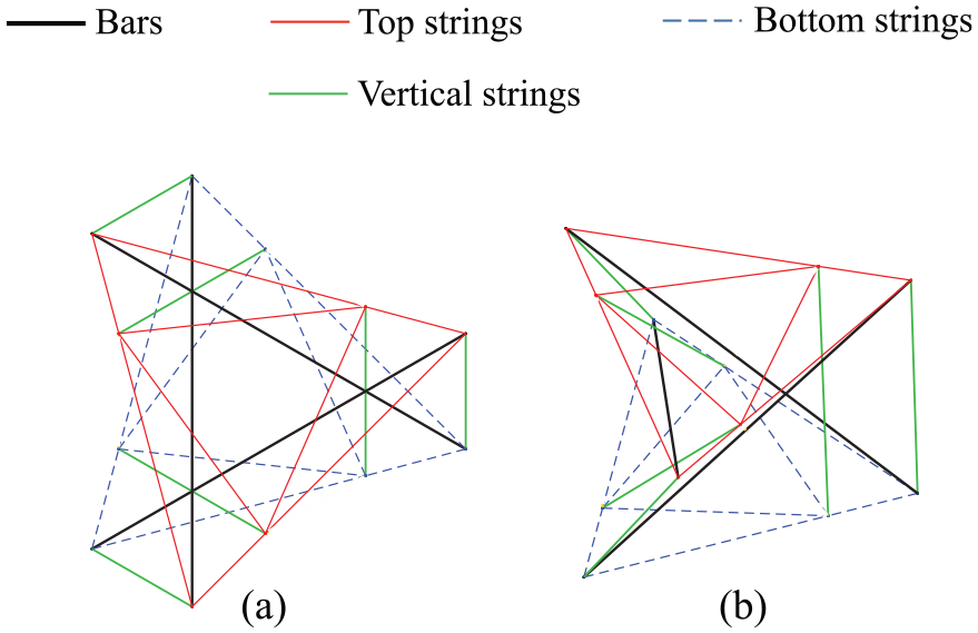
A typical portion of a tensegrity structure is illustrated in Figure 1. The bars and strings are connected at nodes. The number of nodes, bars, and strings in the structure are denoted as

Portion of a tensegrity structure showing the position vector of the ith node (
The matrices

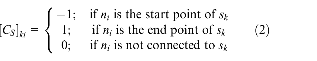
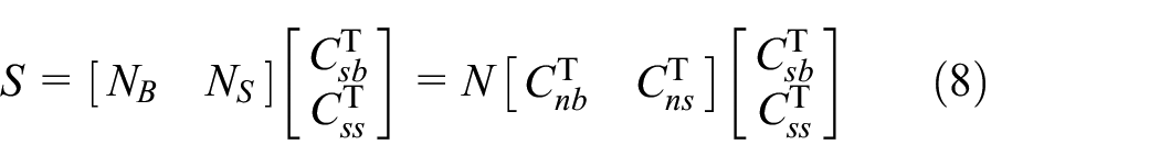
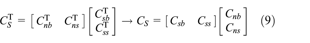
The bar and string matrices B and S are related to the node matrix N through these connectivity matrices as follows

Dynamics of tensegrity structures
The resultant vector of externally applied forces at the ith node is denoted as
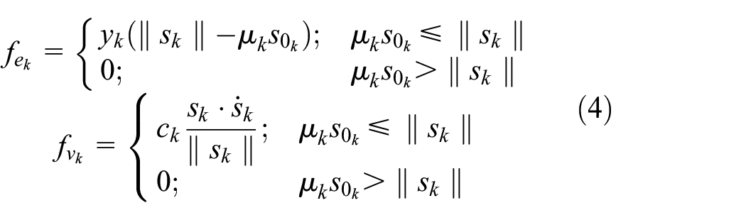
where the scalars
The diagonal matrix containing the tensile force per unit length of each string in its diagonal components is denoted
The matrix containing the position vectors of the nodes at the end points of the bars is denoted as

The bar matrix can then be obtained as follows

where

The string matrix S is obtained from
where
Having introduced the aforementioned matrices, we now proceed to summarize the equations that describe the dynamics of tensegrity structures. In the model considered here, the nodes may be subject to linear constraints

where
The node matrix N and the bar and string connectivity matrices
Node positions and connectivity matrices of tensegrity plates
The node positions and connectivity matrices required to fully define the configuration of tensegrity plates are presented here. Such data are provided for the minimal tensegrity plate and for the new extended tensegrity plate.
Minimal tensegrity plate
The tensegrity plate described in this section is formed by the repetition of a tensegrity unit known as the minimal regular 3 bar prism, which is illustrated in Figure 2. This unit has been used to form tensegrity plates,21,24,25 towers,26,27 beams,
28
and masts.
11
The unit is called minimal because it has the minimum number of strings (nine) required to form a stable pre-stressable prism with 3 bars. It is called regular because its top and bottom faces are regular polygons, which in this work are equilateral triangles. As shown in Figure 2(a), the top and bottom triangles lie in parallel planes and are contained within circumscribing circles of radii
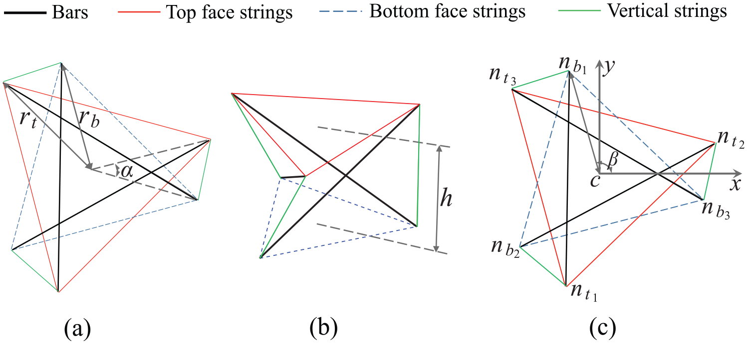
Geometry of the minimal regular 3 bar prism: (a) radii of top (
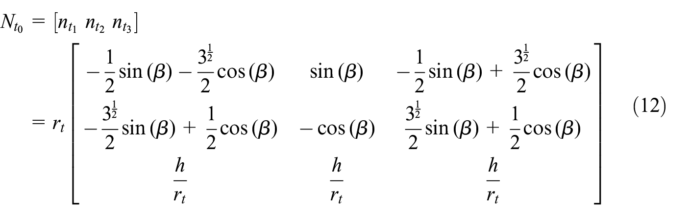
The local coordinate system illustrated in Figure 2(c) is established for the prism and its origin is located at the center of the bottom triangular face. The position vector of the origin is denoted as

where

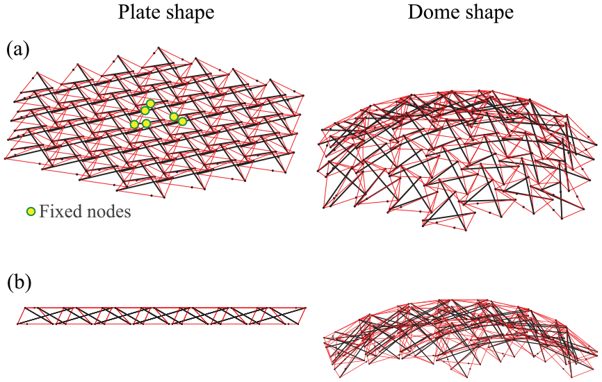
A flat tensegrity plate can be formed by assembling 3 bar prisms as shown in Figure 3(a). All the prisms comprising the plate have the same thickness h and the same top and bottom radii

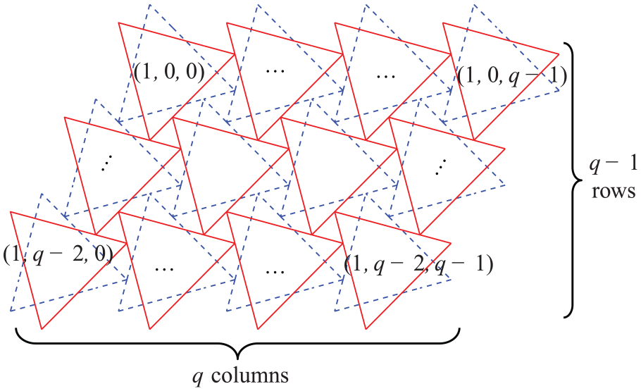
The prisms are arranged in concentric rings, where the number of rings is denoted as the complexityq of the plate. For example, the complexity of the plate in Figure 3 is 4. A plate of complexity q contains

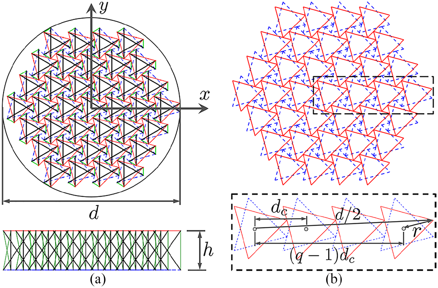
Geometry of a tensegrity plate: (a) top and side views showing the global coordinate system, plate diameter d, and thickness h and (b) prism radius r and distance between adjacent units
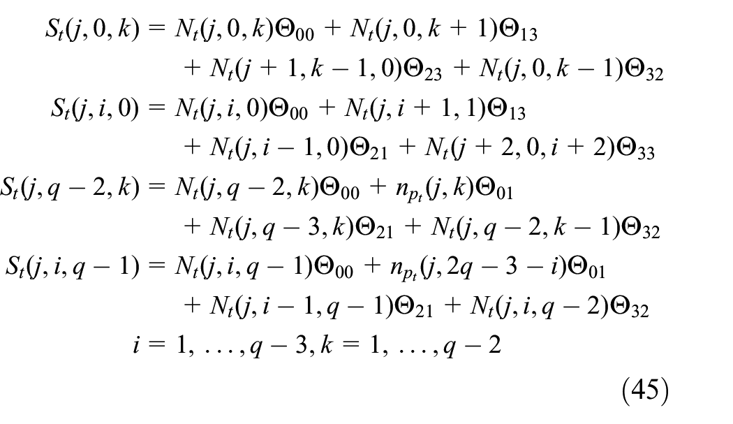
The geometry of a tensegrity plate is defined by its diameter d, thickness h, and complexity q. To establish systematic analytical formulations for the node positions and connectivity matrices, the prisms are divided into four parts as shown in Figure 4. Part 0 has only one prism, the central unit, and each of the other three parts (Parts 1, 2, and 3) have
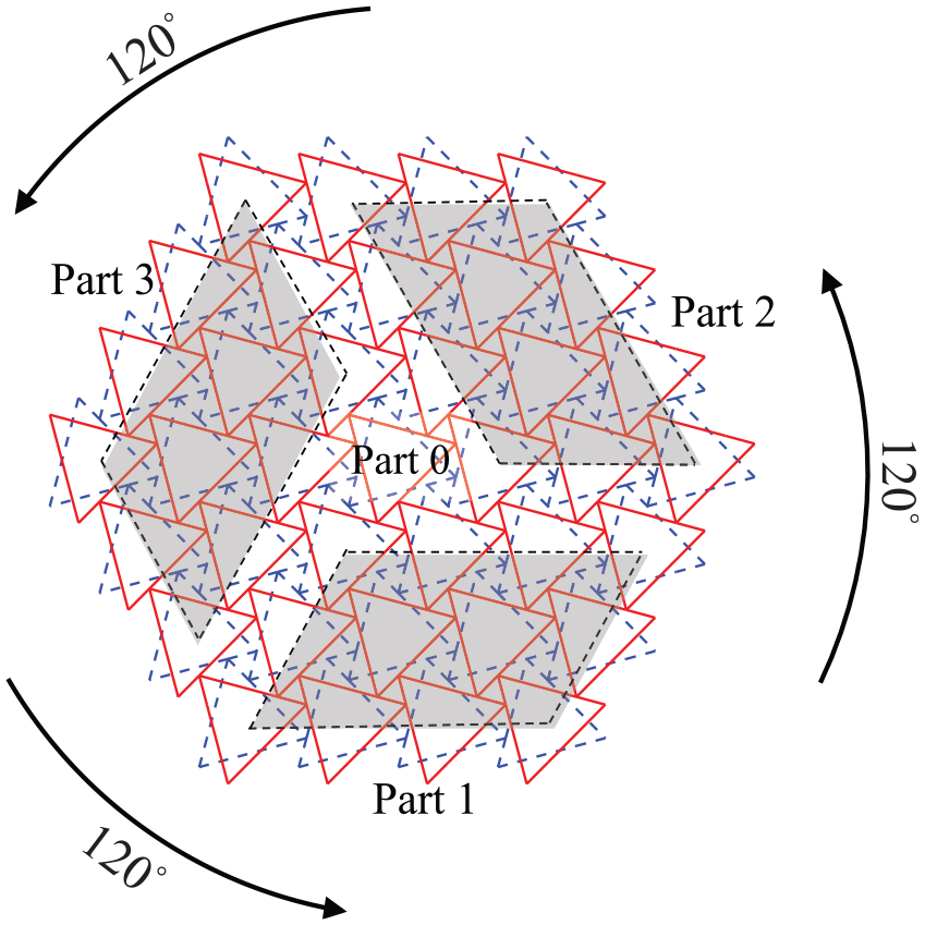
Groups of prism units forming a tensegrity plate.
Labels of prism units in Part 1 (refer to Figure 4).
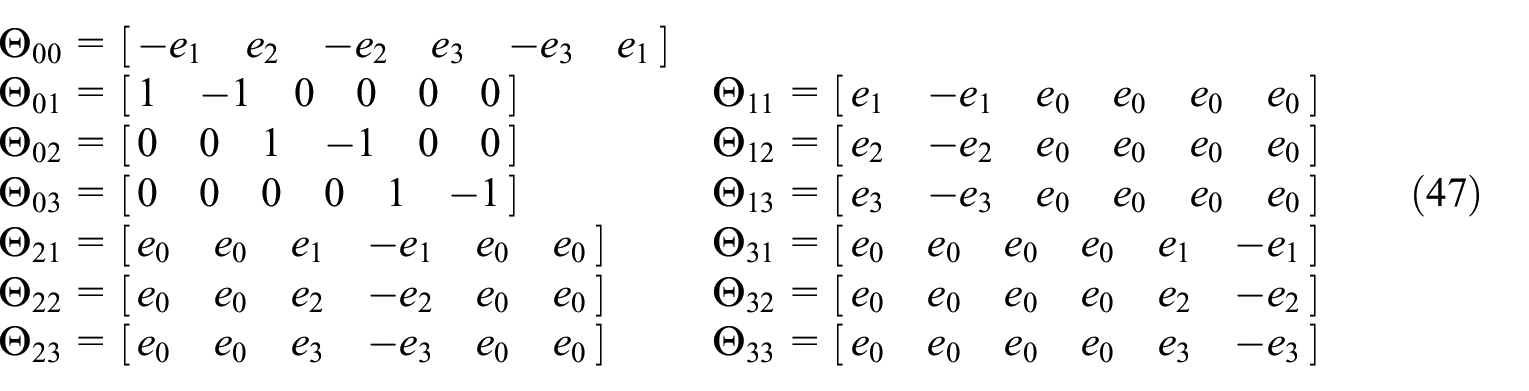
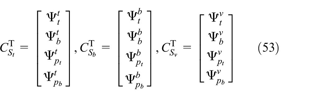
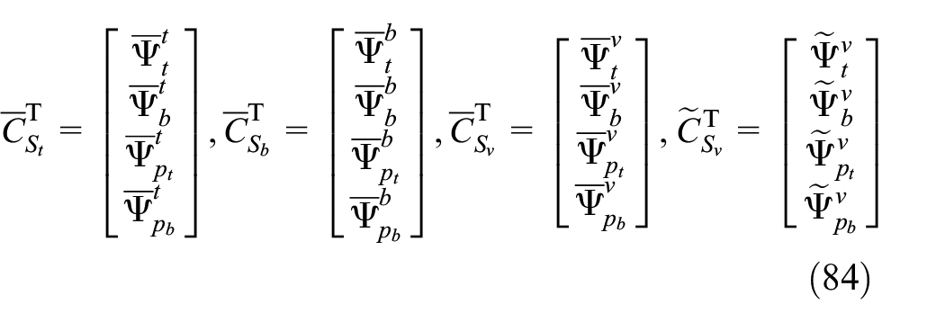
The top and bottom node matrices of a unit
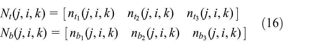
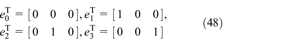
The position vectors of the top and bottom nodes of each part are placed in the matrices
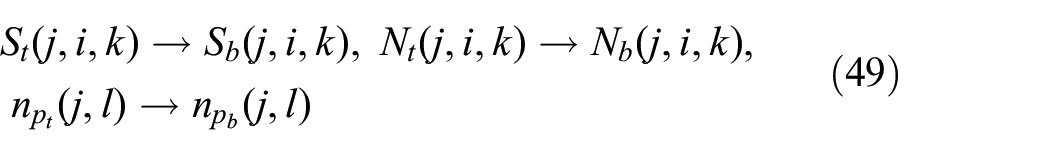
and

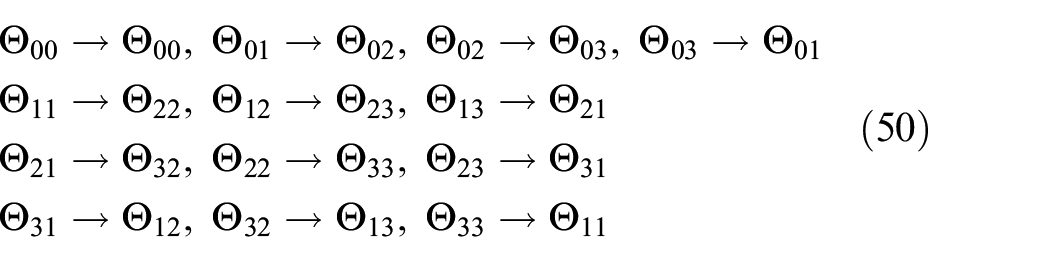
The matrix

and
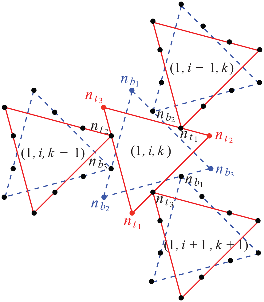
Units adjacent to prism
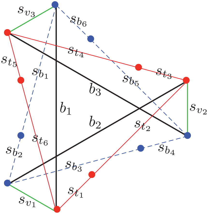
Bar and string members of a prism in a tensegrity plate.
The top, bottom, and vertical string matrices of unit (
The matrices
and
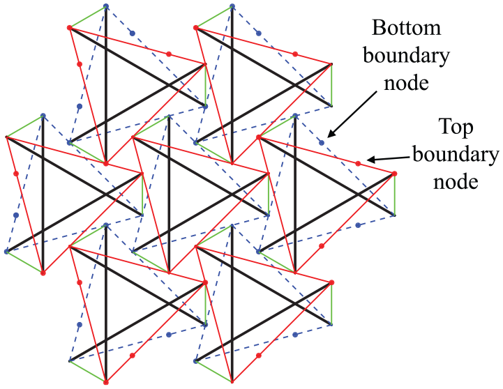
Top and bottom nodes at the boundary of a minimal plate.
The number of prism units in the plate is denoted

In total, a minimal tensegrity plate has

where

Similarly, the bar matrixB of the tensegrity plate is given as

where the matrices

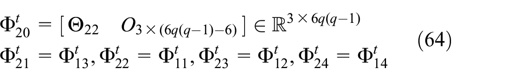
where
and the matrices
Node positions
The node positions of tensegrity plates are calculated through the four steps outlined in this section.
Step 1. Calculate the node positions of each prism in its local coordinate system. The radius r of each prism is calculated from the complexity q and plate diameter d using equation (15). The node matrices of each prism in its local coordinate system (
Step 2. Determine the location of the origin of the local coordinate systems for prisms in Parts 0 and 1 in the global coordinate system. The origin of the local coordinate system of the single unit of Part 0,

The origin of the local coordinate system of prisms in Part 1,
where
and the distance between adjacent units,
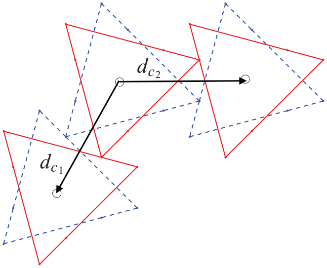
Vectors
Step 3. Determine the node positions for prisms in Parts 0 and 1. The node positions of prisms in Parts 0 and 1 are obtained as follows
where ⊗ denotes the Kronecker product,
Step 4. Determine the node positions for units in Parts 2 and 3. The node locations for prisms in Parts 2 and 3 are calculated by applying rotation transformations to the node locations of Part 1 with respect to the z-axis of the global coordinate system. First, define
It is observed in Figure 4 that the positions of the nodes in Parts 2 and 3 can be determined by rotating those of Part 1 by
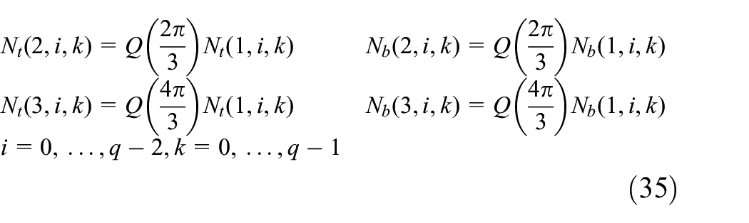
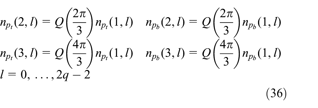
where
Connectivity matrices
The subdivision of the node matrix N in equation (24) allows us to find the matrices of nodes that connect to bars,
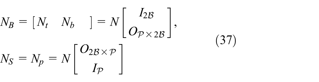
where

As shown in the node and member labels of Figures 2(c) and 7, the lth bar of a prism connects the lth bottom node and the lth top node in the same unit,

Equations (39), (37), and (26) allow us to write the relation between

Using equations (6) and (40), the matrix

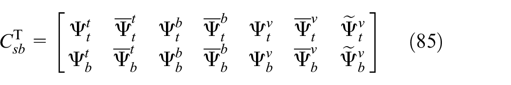
The bar connectivity matrix

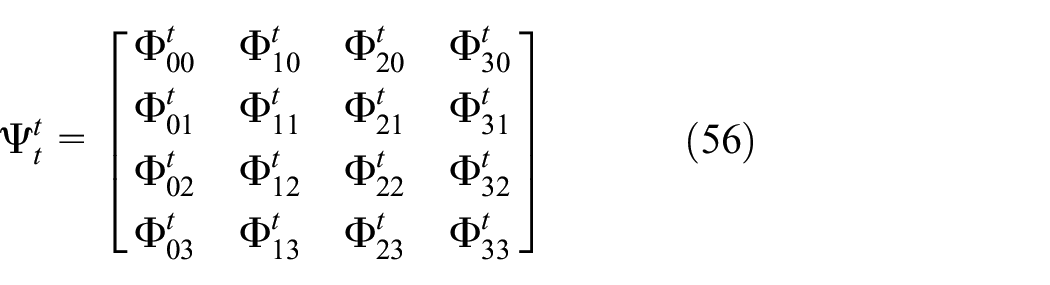
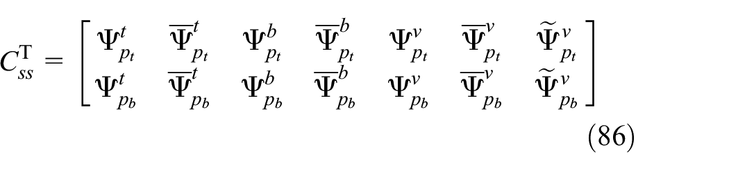
The construction of the string connectivity matrix

and the top string matrices for the corner units, boundary units, and interior units of Parts
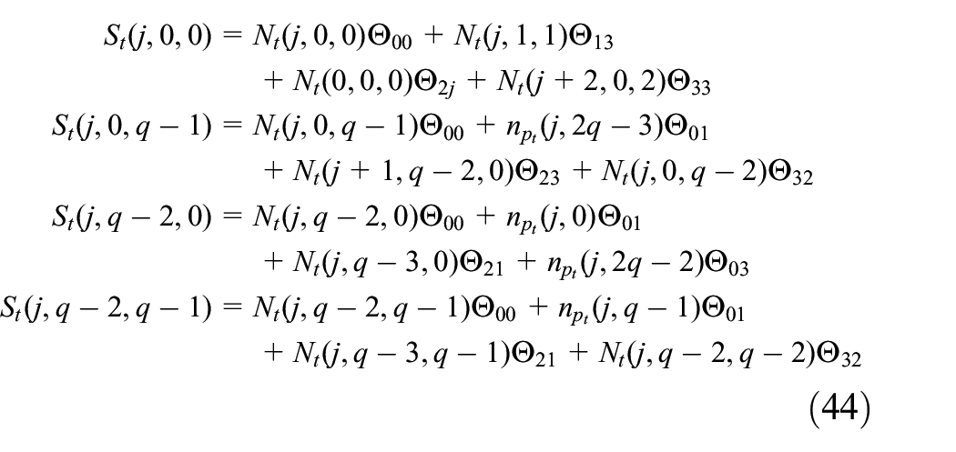

where the matrices
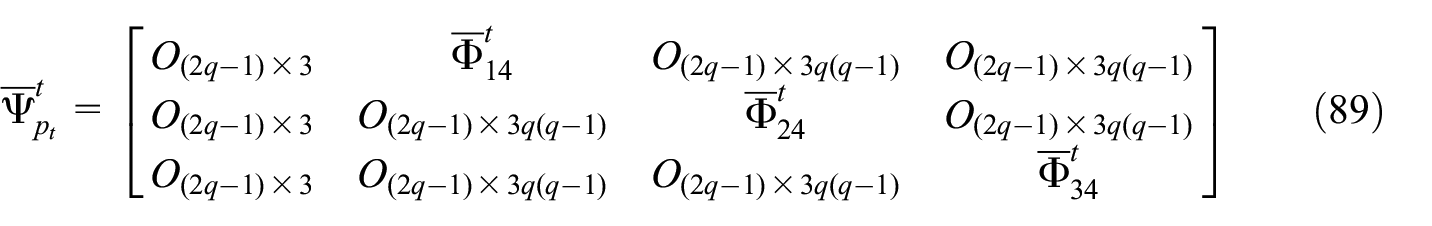
and the vectors
The bottom string matrices for all the units are obtained by making the following substitutions in equations (43)–(46)
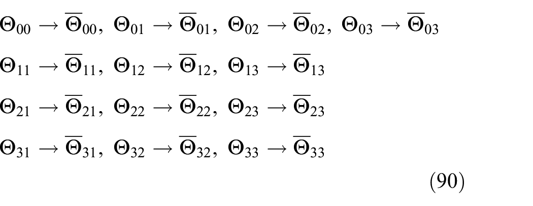
In the above equations (49) and (50), the right arrow symbol “→” is used to denote substitution. For example,
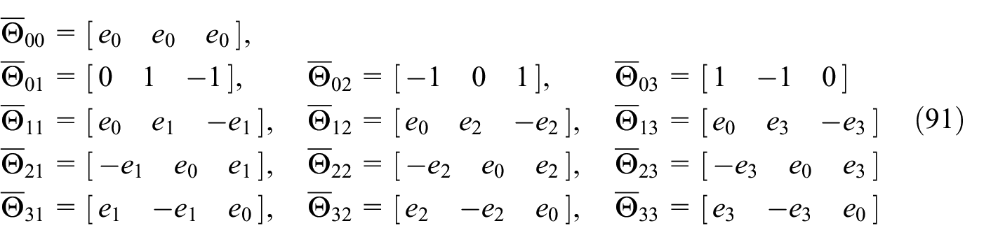
Unlike the top and bottom strings, the vertical strings are connected only to the top and bottom nodes of the same unit (see Figure 2). Therefore, the vertical string matrix is written as follows

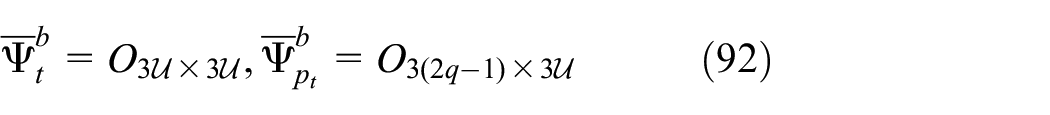
After determining the string-node connectivity for all the prisms of the plate, the next step is to use such information to formulate the string connectivity matrix

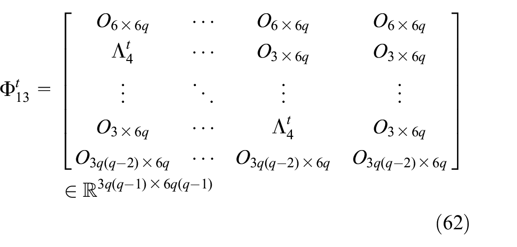
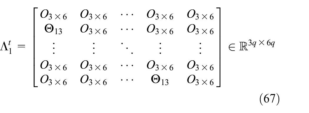
where
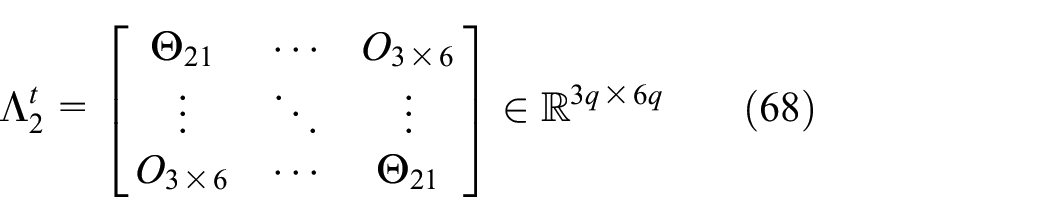
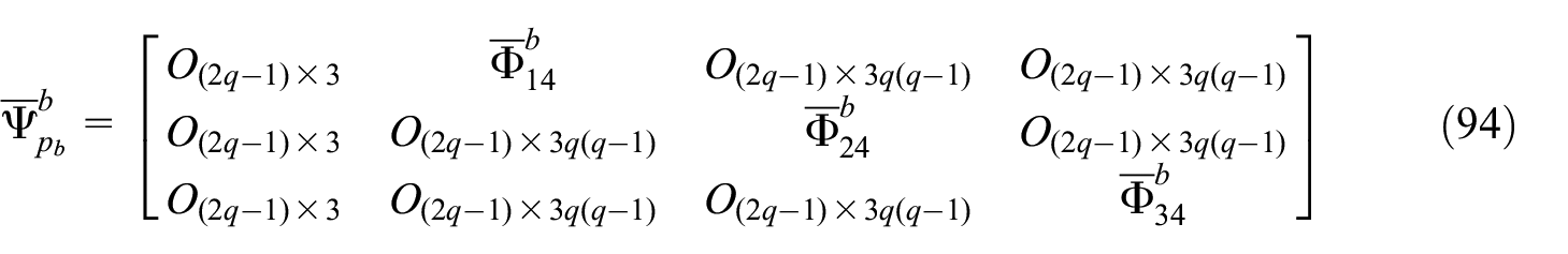
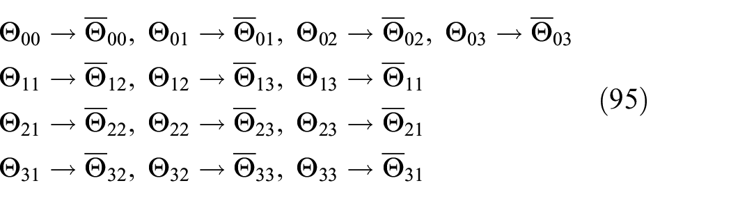
Similarly, the matrices

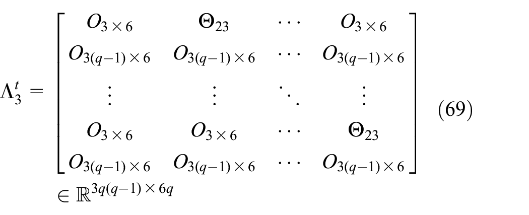
The matrices

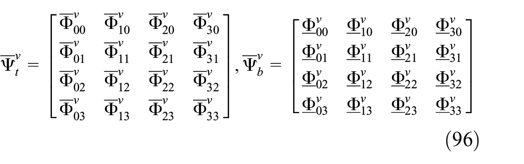
Also, using the information of equations (43)–(46), the matrices

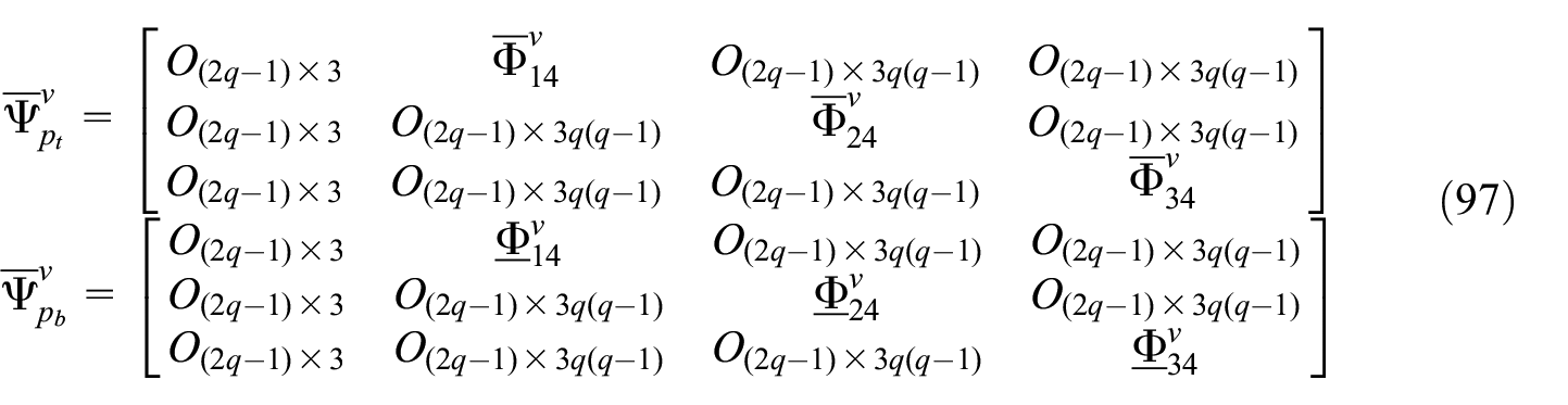
where the matrices


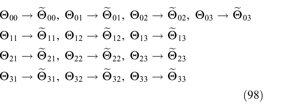
The matrices


The matrices

The matrices
The matrices

This concludes the determination of the connectivity matrices for minimal tensegrity plates of any complexity.
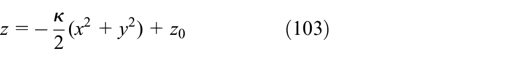
Extended tensegrity plate
A new type of plate is proposed herein on the basis of the minimal tensegrity plate. The fundamental unit of the new plate is obtained by adding three top inner strings, three bottom inner strings, and three vertical inner strings to a minimal regular 3 bar prism. This prism is denoted as extended regular 3 bar prism and is illustrated in Figure 10. The additional strings increase stiffness in directions that have large compliance in conventional minimal prisms. A directional stiffness comparison between the minimal and the new prism is not provided here but is recommended as future work. The definitions of top radius
Extended regular 3 bar prism: (a) top view and (b) perspective view.
Nodes and members of an extended 3 bar prism: (a) nodes and (b) added members. The labels of the other members are provided in Figure 7.
The extended tensegrity plate is formed by arranging extended 3 bar prisms in concentric rings as shown in Figure 12. The diameter d, distance between centers of adjacent prisms

Top view of a tensegrity plate formed by extended regular prisms.
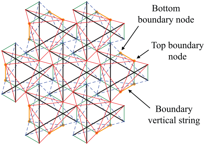
Boundary nodes and boundary vertical strings of the extended 3-bar prism plate.
The division of the plate into four parts as illustrated in Figure 4 is also employed here to define the labels of nodes and members for the 3 bar prism extended plate. The nodes and bar members of the 3 bar prism extended plate are identical to those of the minimal plate. Therefore, the node matrix N and bar matrix B of the extended 3 bar prism plate correspond to those provided in equations (24) and (26), respectively. The process for the determination of the node positions for the extended 3 bar prism plate is also the same as that outlined for the minimal plate. The string matrix S for the extended plate, however, is different than that of the minimal plate because further strings are added in the extended plate. Let

The matrices
and

The vectors along the boundary vertical strings (illustrated in Figure 13) located in Part j,

The matrix of boundary string vectors of the entire plate,
After defining the previous matrices, the string matrix

where
Connectivity matrices
As previously mentioned, the node matrix N and the bar matrix B of the extended plate are identical to those of the minimal one; therefore, the bar connectivity matrix
where
Similarly, the matrices
The matrices


The matrices
where
The matrices

The matrices
where the matrices
The matrices
and the matrices

where the matrices
The matrices

This concludes the presentation of the node positions and connectivity matrices for the minimal and extended tensegrity plates. It must be noted that rows of the connectivity matrices
Implementation example: morphing tensegrity plates into domes
This section provides a demonstration of the implementation of the node positions and connectivity matrices derived in the previous sections. The demonstration entails dynamic simulations of tensegrity plates morphing into domes. In-depth analysis of the dynamics problem, material selection, or structural optimization of the resulting domes are not performed here, but are recommended for future studies. The dynamics model for tensegrity structures used here was summarized earlier in this article. Such dynamic equations are implemented in MATLAB® using ODE4.
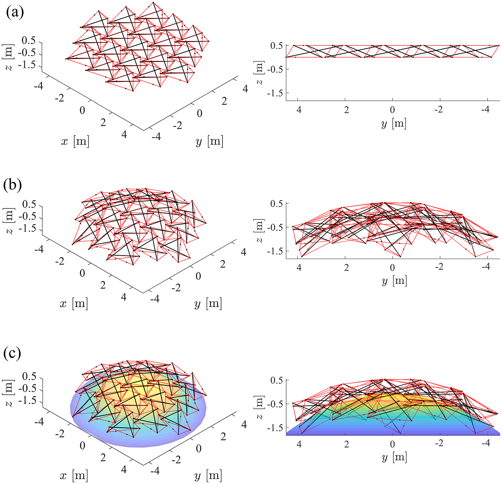
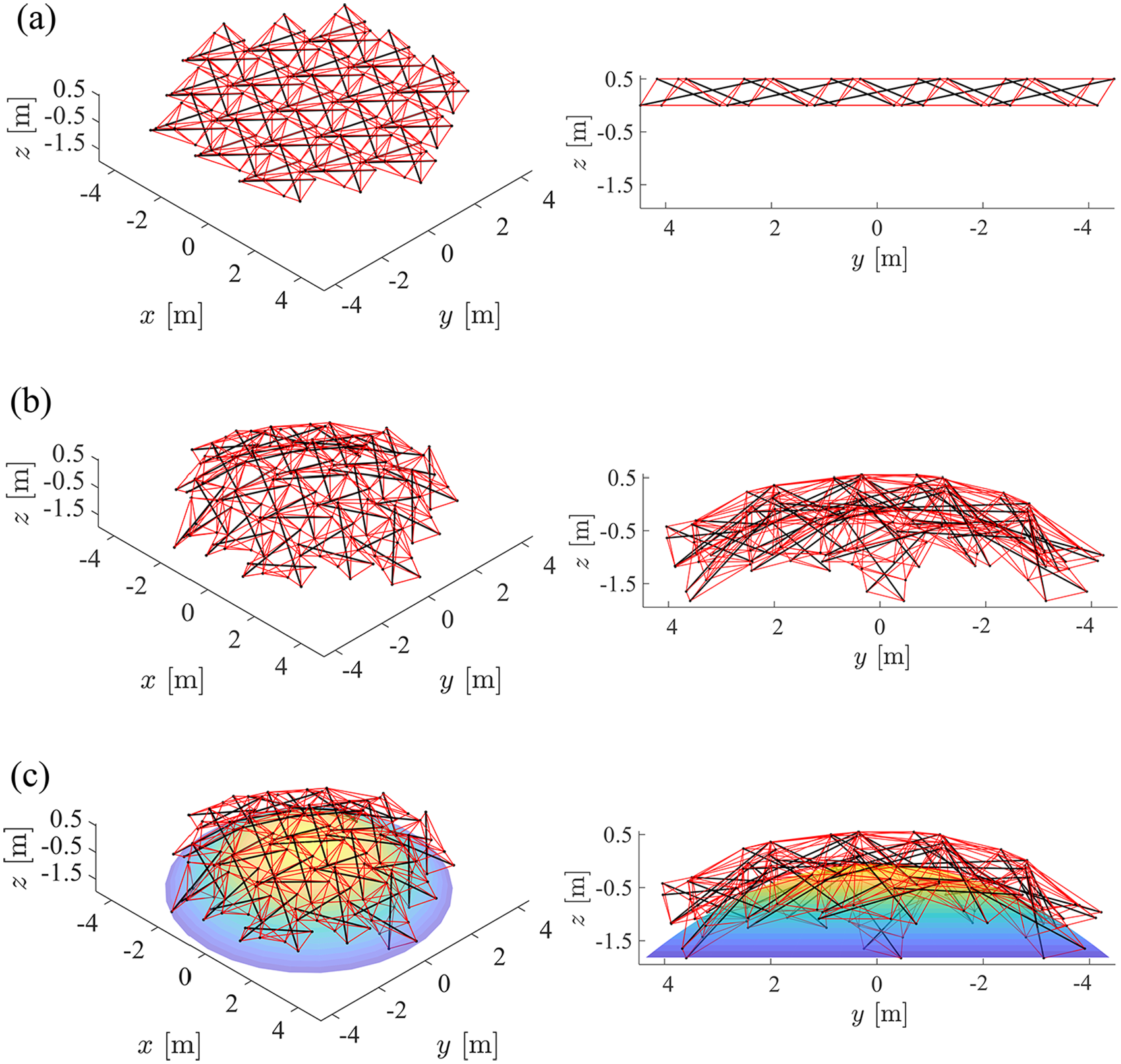
The shape of a tensegrity plate can be altered by changing the rest lengths of its strings. To transform a plate into a dome, the rest lengths of all the bottom strings are shortened simultaneously, while the rest lengths of all the top and vertical strings are kept constant throughout the transformation. The transformation of a tensegrity plate toward a dome obtained from such a strategy is illustrated in Figure 14.
Transformation of a tensegrity plate into a dome performed by shortening the rest lengths of the bottom strings of the plate: (a) perspective view and (b) side view.
The following expression for the rest length ratios
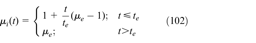
where
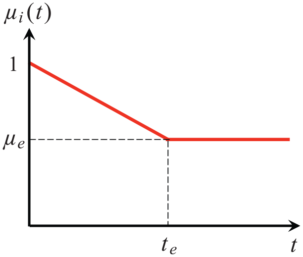
Relationship between rest length ratio
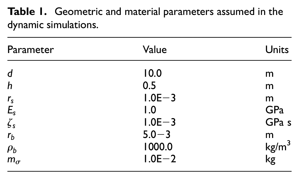
The geometric and material parameters used in the dynamic simulations are provided in Table 1. All the strings have radius
Geometric and material parameters assumed in the dynamic simulations.
To observe the influence of the string shortening rate on the dynamics of the plates/domes, we show two simulations of a dome transformed from the same initial plate configuration using the same final rest length ratio
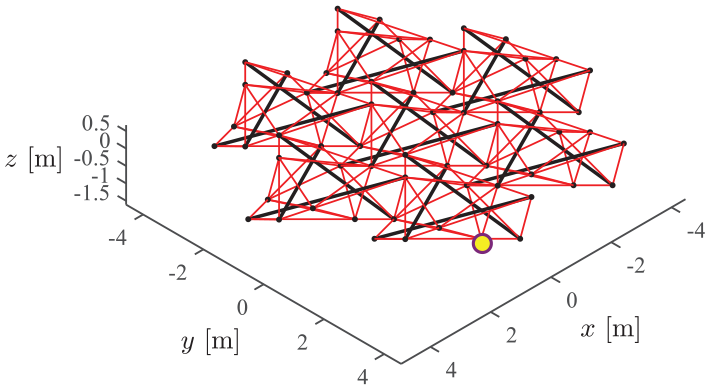
Schematic of an extended tensegrity plate of complexity
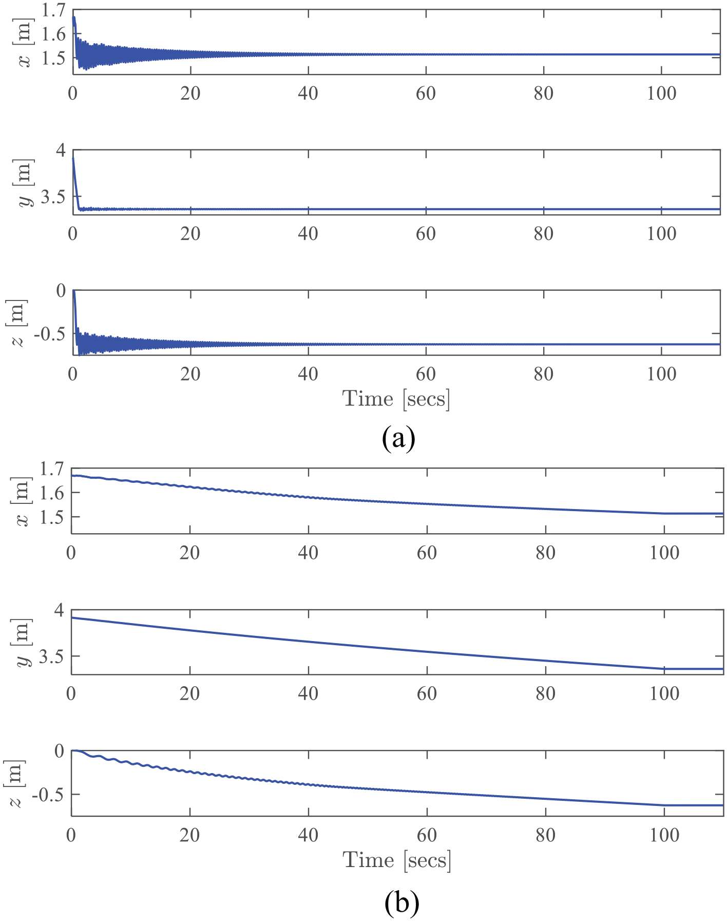
Position history of the node highlighted in Figure 16: (a) shortening time
In the next examples, the shape of the domes generated by shortening the bottom strings of the plates through equation (102) is compared with a parabola. Such a parabolic shape may be useful in potential applications such as antennas, mirrors, or civil constructions. Minimal and extended plates of complexities

Schematics of the studied plate topologies and complexities.
The final shape of the bottom face of the domes is compared against a parabola with the following formulation
where
where the matrix
and
where
Results showing
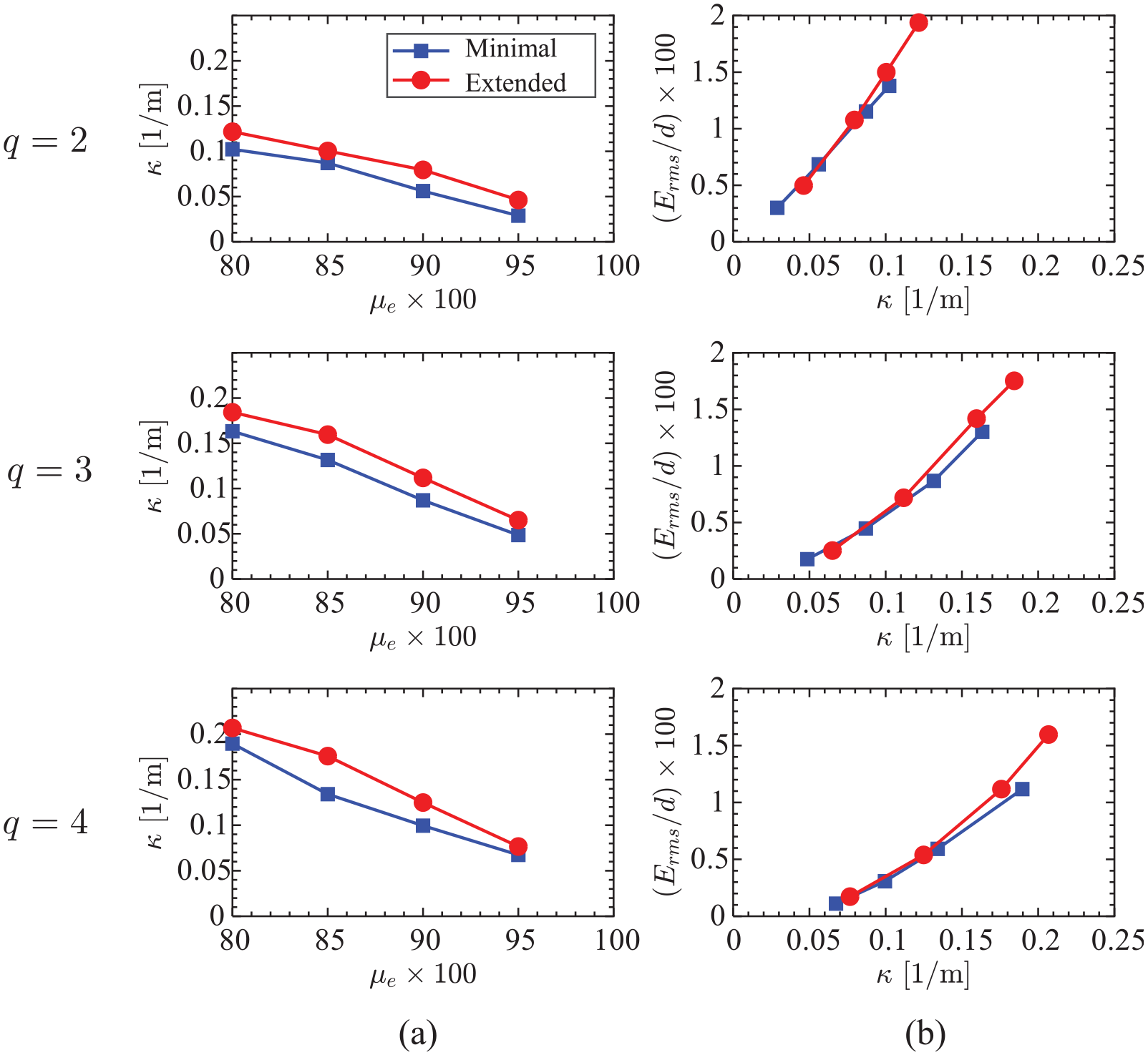
Comparison of the final dome shape of minimal and extended tensegrity plates for all the considered complexities: (a) final curvature
Schematics of curvature
Configurations of minimal and extended tensegrity plates of complexity
Configurations of a minimal tensegrity plate of complexity
Configurations of an extended tensegrity plate of complexity
Conclusion
This article presented systematic analytical equations for the node positions and connectivity matrices of tensegrity plates with two different topologies. Such node positions and connectivity matrices are the fundamental descriptors in the modeling and design of tensegrity structures. We first considered the minimal tensegrity plate formed by the repetition of a tensegrity unit known as the minimal regular 3 bar prism. The unit is called minimal because it has the minimum number of strings (nine) required to form a stable pre-stressable prism with 3 bars. The minimal tensegrity plate has been studied in the literature, but sets of analytical formulas for their node positions and connectivity matrices were not available. Such analytical formulations allow for efficient computations and would facilitate future research efforts in the analysis and design of tensegrity plates. In addition, we provided the connectivity matrices of an extended tensegrity plate. The new plate has additional strings that can potentially increase stiffness in directions that have large compliance in conventional minimal plates. A directional stiffness comparison between the minimal and the new plate is not provided here but is recommended as future work.
To derive the node positions and connectivity matrices, the prisms in the hexagonal plates were divided into four parts, where Part 0 contains only the prism at the center and the surrounding three parts have the same number of prisms and are placed in a three-fold symmetric arrangement. This division simplified the derivation of analytical formulas for the connectivity matrices and node positions. The derived formulas allow inputs such as plate diameter, thickness, and complexity (number of rings of prism units forming the plate). The Supplemental Material of this article includes MATLAB® scripts that output the derived node positions and connectivity matrices for tensegrity plates given their size parameters and complexity. Rows of the connectivity matrices can be removed to eliminate bar or string members. This adds a higher level of flexibility in the topology design of tensegrity plates using the formulation presented here. Finally, a demonstration of the implementation of the node positions and connectivity matrices in the modeling of tensegrity structures was briefly provided. The demonstration consisted of dynamic simulations of tensegrity plates morphing into domes.
Supplemental Material
extended_prism_plate – Supplemental material for Analytical equations for the connectivity matrices and node positions of minimal and extended tensegrity plates
Supplemental material, extended_prism_plate for Analytical equations for the connectivity matrices and node positions of minimal and extended tensegrity plates by Shuhui Jiang, Robert E Skelton and Edwin A Peraza Hernandez in International Journal of Space Structures
Supplemental Material
minimal_prism_plate – Supplemental material for Analytical equations for the connectivity matrices and node positions of minimal and extended tensegrity plates
Supplemental material, minimal_prism_plate for Analytical equations for the connectivity matrices and node positions of minimal and extended tensegrity plates by Shuhui Jiang, Robert E Skelton and Edwin A Peraza Hernandez in International Journal of Space Structures
Footnotes
Acknowledgements
S.J. would like to acknowledge the financial support from the National Natural Science Foundation of China (NSFC) Grant No. 51578492. Any opinions, findings, and conclusions expressed in this material are those of the authors and do not necessarily reflect those of the National Natural Science Foundation of China. E.A.P.H. acknowledges the start-up faculty support from the Department of Mechanical and Aerospace Engineering at the University of California, Irvine.
Declaration of conflicting interests
The author(s) declared no potential conflicts of interest with respect to the research, authorship, and/or publication of this article.
Funding
The author(s) received no financial support for the research, authorship, and/or publication of this article.
Supplemental material
Supplemental material for this article is available online.
References
Supplementary Material
Please find the following supplemental material available below.
For Open Access articles published under a Creative Commons License, all supplemental material carries the same license as the article it is associated with.
For non-Open Access articles published, all supplemental material carries a non-exclusive license, and permission requests for re-use of supplemental material or any part of supplemental material shall be sent directly to the copyright owner as specified in the copyright notice associated with the article.