
Abstract
This article highlights the design potentials of a recently proposed form-driven approach for bending-active tensile structures, in which the geometry of the actively bent elements can be directly defined without the recourse to a form-finding procedure. The approach is applied to the design of a lightweight sun-shading system that can be used to protect glazed building façades, and in which actively bent beams are restrained by pre-stressing strips. Other than structural requirements, the geometry of this hybrid structure is informed by functional and environmental considerations to prevent overheating and glare inside the building.
Keywords
Introduction
This article deals with the conceptual design of a static bending-active tensile structure, a fixed structure whose geometry derives from a reversible bending process applied to slender beams, which are restrained with tensile elements.1,2 This structure consists of a sun-shading façade system, which is exemplarily applied to the glass curtain wall of one of the office buildings of the ETH Science City Campus in Zurich (Switzerland), with the aim of improving the thermal and visual comfort of the building’s occupants.
The proposed sun-shading system is made of slender beams that are actively bent and a series of pre-stressed strips working in tension (Figure 1). The strips fulfil two functions: on the one hand, they shape and stabilize the actively bent beams; and on the other hand, they act as sun-louvers preventing the sun beams to hit the glazed façades (Figure 7). Each beam is anchored at its ends to the frame of the curtain wall. Its shape is dependent, on the one hand, on its bending stiffness, which varies along its axis due to a variable cross-section geometry; and on the other hand, on the restraining effect of the pre-stressing strips, which, in turn, bring additional stability and stiffness to the construction. The global geometry of the structure is informed by a solar analysis to prevent overheating and glare inside the building while maintaining appropriate internal lighting conditions (illuminance levels within an acceptable range of 100–3000 lux and reduction of the glare risk on the work plane).
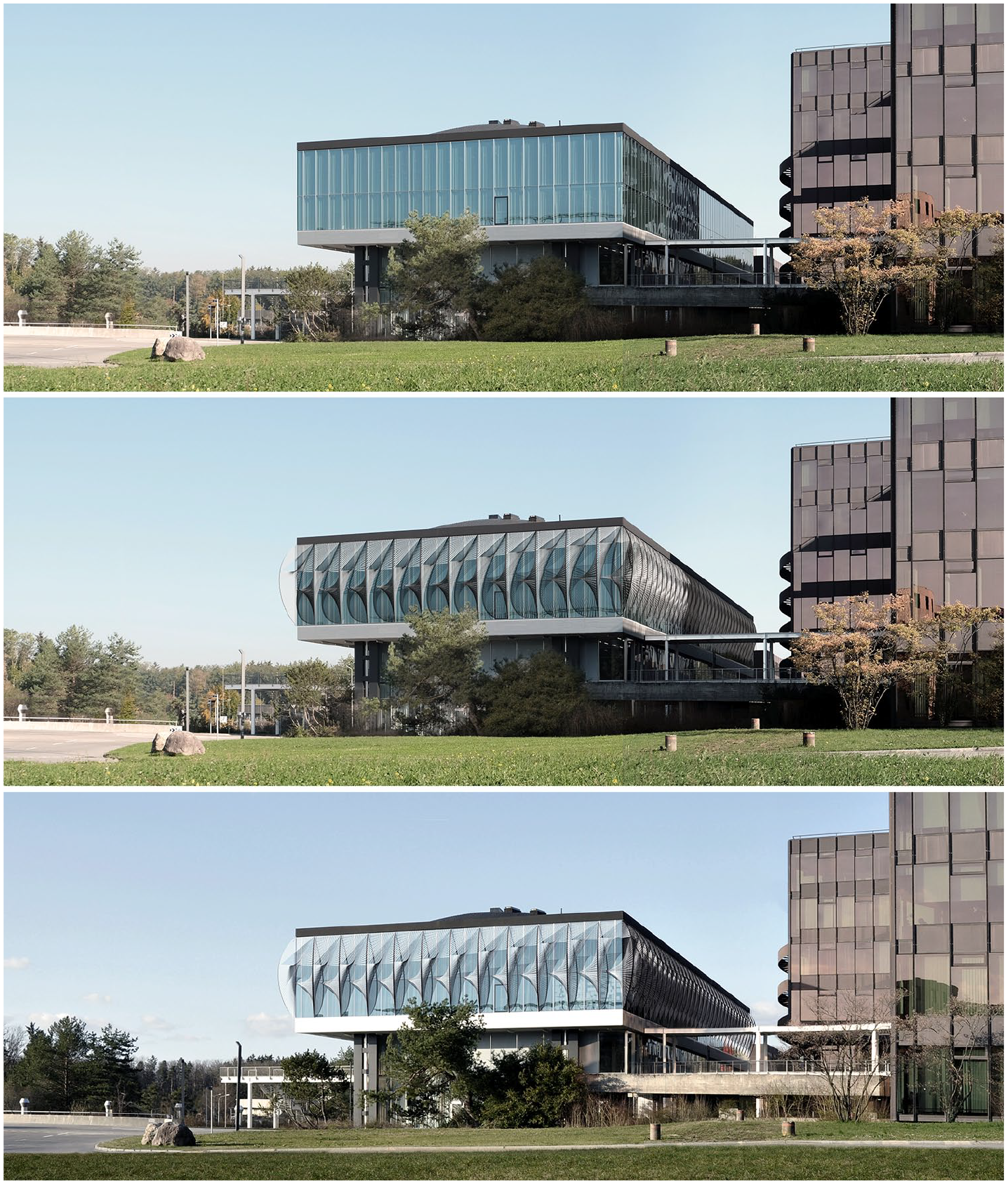
South-west façade of the HIB building at ETH Science City Campus in Zurich: photograph of the current state (top); collages with the proposed sun-shading bending-active tensile structure at two distinct times of the year: September 21 11:30 (middle) and March 21 14:30 (bottom).
In this design context, the form-driven approach to bending-active tensile structures proposed by Boulic and Schwartz 3 has been adopted. Unlike conventional form-finding approaches, in the form-driven approach, the bent equilibrium geometry of two-dimensional (2D) bending-active beams, which are restrained with a three-dimensional (3D) system of tensile elements, is the input of the design process rather than the output. The conditions for such bending-active beams to be in static equilibrium are deduced using graphic statics and they are used to define the geometry of the tensile restraining system.
Motivation
In architecture, bending-active structures can be very valuable solutions for the design of façade systems. This has been effectively demonstrated in relation to kinetic structures made of bending-active plates.4–7 Regarding static bending-active tensile structures, which is the subject of this article, various aspects motivate their use in the context of façade design. First of all, bending-active tensile structures are remarkably lightweight systems, as they take advantage of the mutual interaction between actively bent elements and tensile elements and make efficient use of the structural performance of both sub-systems. This property allows bending-active tensile structures to be used for building façade retrofitting. Second, bending-active tensile structures provide integrated solutions where both actively bent and tensile elements can perform for various functional purposes other than the structural one, such as sun-shading or more generally protection from the elements.8–10 Third, from an architectural standpoint, bending-active tensile structures are generally endowed with distinctive aesthetic connotations and are characterized by a strong formal expression.
The conventional way to design bending-active structures is through form-finding (section ‘Form-finding vs form-driven approaches’). This approach, however, does not offer a direct control over the final bent shape, which would be beneficial during the design phase as the geometry strongly influences the sun-shading performance of the structure.
Objective and contribution
The objective of this article is to highlight the strengths of the form-driven approach 3 in comparison to conventional form-finding approaches, especially for those design scenarios in which it is more convenient to consider the bent equilibrium geometry as the input rather than the output of the design process. In this regard, a self-supporting sun-shading façade system is used as a case study since both structural and sun-shading requirements, which strongly rely on the geometry of that system, have to be addressed simultaneously.
In this article, the theoretical part of the form-driven design approach presented by Boulic and Schwartz 3 has been extended. On the one hand, contrary to the original formulation, which was based on the force density method (FDM), 11 a new design procedure based only on geometric constructions of graphic statics has been introduced to define the layout of the tensile cables. On the other hand, a new methodology to take into account the specific material properties of the bending-active beams has been developed.
Through the design application of the bending-active tensile façade system, the article eventually demonstrates the potential of the from-driven approach to effectively integrate structural, functional, manufacturing and environmental requirements.
Content
The article is structured as follows. Section ‘Form-driven design of bending-active tensile structures’ synthetically describes the form-driven method that has been employed to generate the geometry of the hybrid bending-active tensile façade system presented in this article. Moreover, this section gives an overview on how the proposed integral design framework articulates the different steps of the design process. Section ‘Design of the bending-active tensile sun-shading system’ defines the indoor comfort evaluation criteria used for the visual and thermal assessment of the designed façade system. This section also outlines the iterative design process based on a thorough solar and visual analysis, which informed the geometry of the proposed sun-shading system. Section ‘Parametric models’ explains in detail the different parametric models on which the proposed integral design framework is based upon. Finally, Section ‘Material investigation and fabrication of a 1:2 scale prototype’ presents the construction of a 1:2 scale prototype of the façade, with a focus on the related material and fabrication investigations.
Form-driven design of bending-active tensile structures
Form-finding versus form-driven approaches
One of the difficulties associated with the design of bending-active structures is the description of the system in its deflected state, particularly due to the geometrical non-linearity of the physical phenomenon of bending. 1 Current methods to address such structural systems are mainly based on form-finding algorithms:
Dynamic Relaxation (DR) with 3-degree-of-freedom (DoF) beam models,12,13 with 4-DoF beam models, 14 with 6-DoF beam models, 15 in combination with the FDM 16 (a more extended review can be found in Lázaro et al.). 17
Projective Constraint-based Solver (using, e.g. the Kangaroo2 18 library by Picker developed for the CAD software Robert McNeel & Associates 19 ).20,21
Finite element method (FEM) with non-linear solvers and mesh-based 25 or iso-geometric-based 26 discretization methods.
Although effective, the above form-finding approaches have the disadvantage of offering only an indirect control over the final equilibrium geometry. This control is generally achieved by iteratively adjusting the input parameters of the form-finding algorithm. Yet, the possibility to define and adjust directly the geometry of the bent elements may appear particularly relevant in those design cases in which other geometry-related requirements are as important as structural performance. This is the case of self-supporting sun-shading façade systems whose geometry should respond at the same time to structural and sun-shading requirements.
The form-driven approach 3 used in this work for the design of bending-active tensile structures represents a complementary solution to the above form-finding approaches, as it allows gaining direct control on the geometry of the system in its deflected state. Besides, as it is based on a simple mechanical model of slender beams and on 2D equilibrium conditions, this form-driven approach offers an intuitive understanding of the mechanical behaviour of bending-active structures, together with the different parameters that rule their equilibrium.
The main difference between form-finding and form-driven approaches lies on the static problem to be solved since its formulation in the two approaches is inverted with respect to each other (Figure 2). In the form-finding approach, the goal is to find the equilibrium geometry that a given bending-active (tensile) system takes under imposed boundary constraints. On the contrary, in the form-driven approach, the aim is to define local and global conditions necessary to meet a given geometrical configuration of equilibrium of the bending-active system. That is, the length
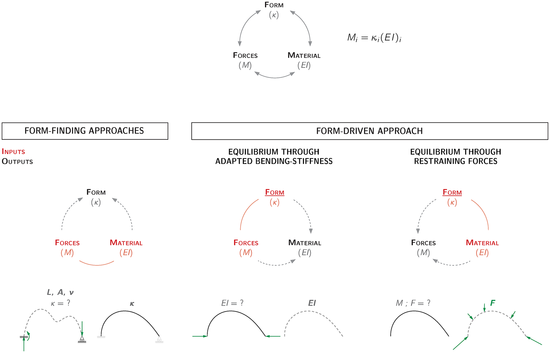
Schematic comparison between a form-finding-based approach and the proposed form-driven approach.
Approaches similar to the form-driven one proposed in this article can be found in the literature. These approaches are based on adapting the bending stiffness of a beam along its axis to control its bent equilibrium geometry under given loads using either empirical or analytical methods. Nicholas and Tamke 27 and Tamke et al. 28 have illustrated in an experimental and empirical way how adjusting the bending stiffness of flexible elements can be used to match target geometry. An analytical description of the curvature–bending stiffness relationship has been employed in this perspective by Bechert et al., 29 under the assumption of constant bending moment. A similar procedure has been used by Brütting et al. 30 to calculate local bending moments along a pinned beam.
In the form-driven approach, the bending stiffness of a bending-active beam is determined using a graphical procedure based on the manipulation of a force diagram. This procedure is valid for any support and loading conditions provided that the global and local equilibriums are fulfilled. The form-driven approach is based on two alternative strategies, which can be also combined, as follows: 3 the bent equilibrium geometry of the beams can be obtained either through adapted bending stiffness or through additional restraining forces (Figure 2).
Form-driven approach
The mechanical model employed in the form-driven approach to describe the equilibrium of a slender beam under plane bending only – that is, without any twist of the cross-sections around the beam’s centre line – has been initially introduced by Boulic and Schwartz. 31 It is based on the assumption that the axial forces in the beam are independent of the mechanical and geometric properties of the beam’s cross-sections, which is to neglect the axial deformation of the beam during bending. In this model, which is utilized to analyze the equilibrium state of a beam in a given geometric configuration, the continuous bending moment along the axis of the beam is converted into discrete pairs of opposite forces. 12 The use of graphic statics, through form and force diagrams, allows for the calculation and visualization of the conditions necessary to equilibrate a beam in a given planar deflected geometry.
As additionally shown by Boulic and Schwartz, 3 the control of the geometries of 2D actively bent elements within a 3D hybrid system can be achieved by addressing successively the equilibrium of the bending-active elements and the one of the tensile elements, provided that equilibrium conditions between the two structural sub-systems are fulfilled. In that procedure, the equilibrium of the beams was addressed with graphic methods and the equilibrium of the tensile elements was obtained through form-finding using the FDM. 11
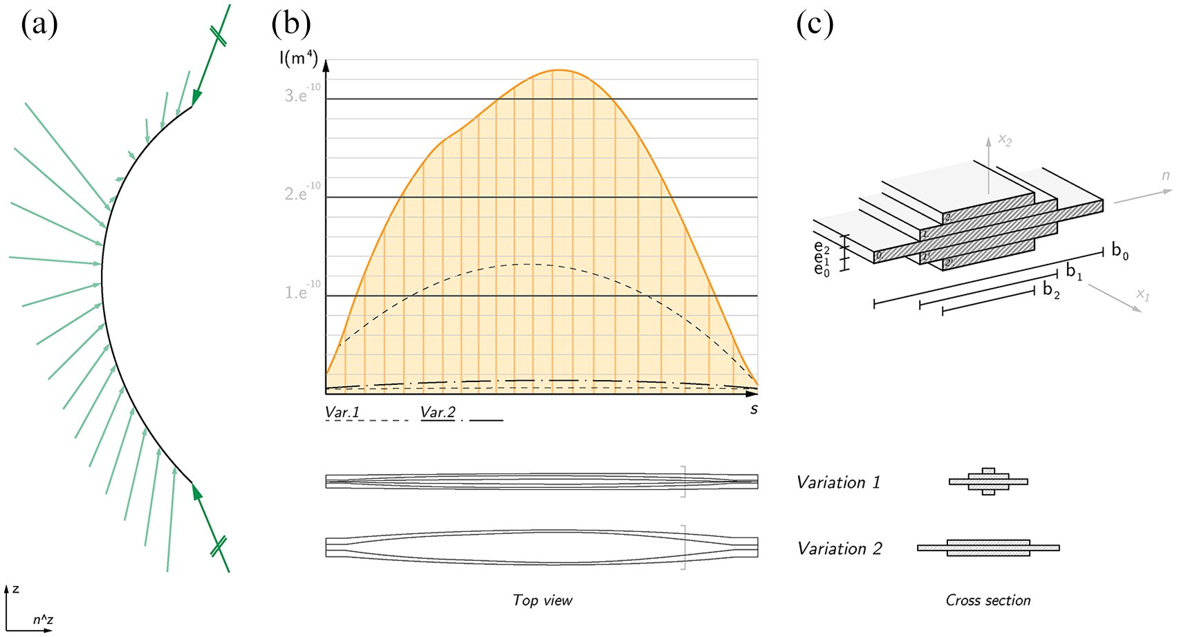
In this article, the bent equilibrium geometry of the beams is obtained through the strategy of adapted bending stiffness (section ‘Form-finding vs form-driven approaches’) as illustrated in Figure 3. In the first step (Figure 3(a)), the desired curved target equilibrium geometry of each of the 2D bending-active beams is defined, considering various aspects, such as structural, functional, and environmental criteria. In the second step (Figure 3(b) and (c)), a compatible set of pre-stressing elements is generated, in such a way that these tensile elements apply a series of forces
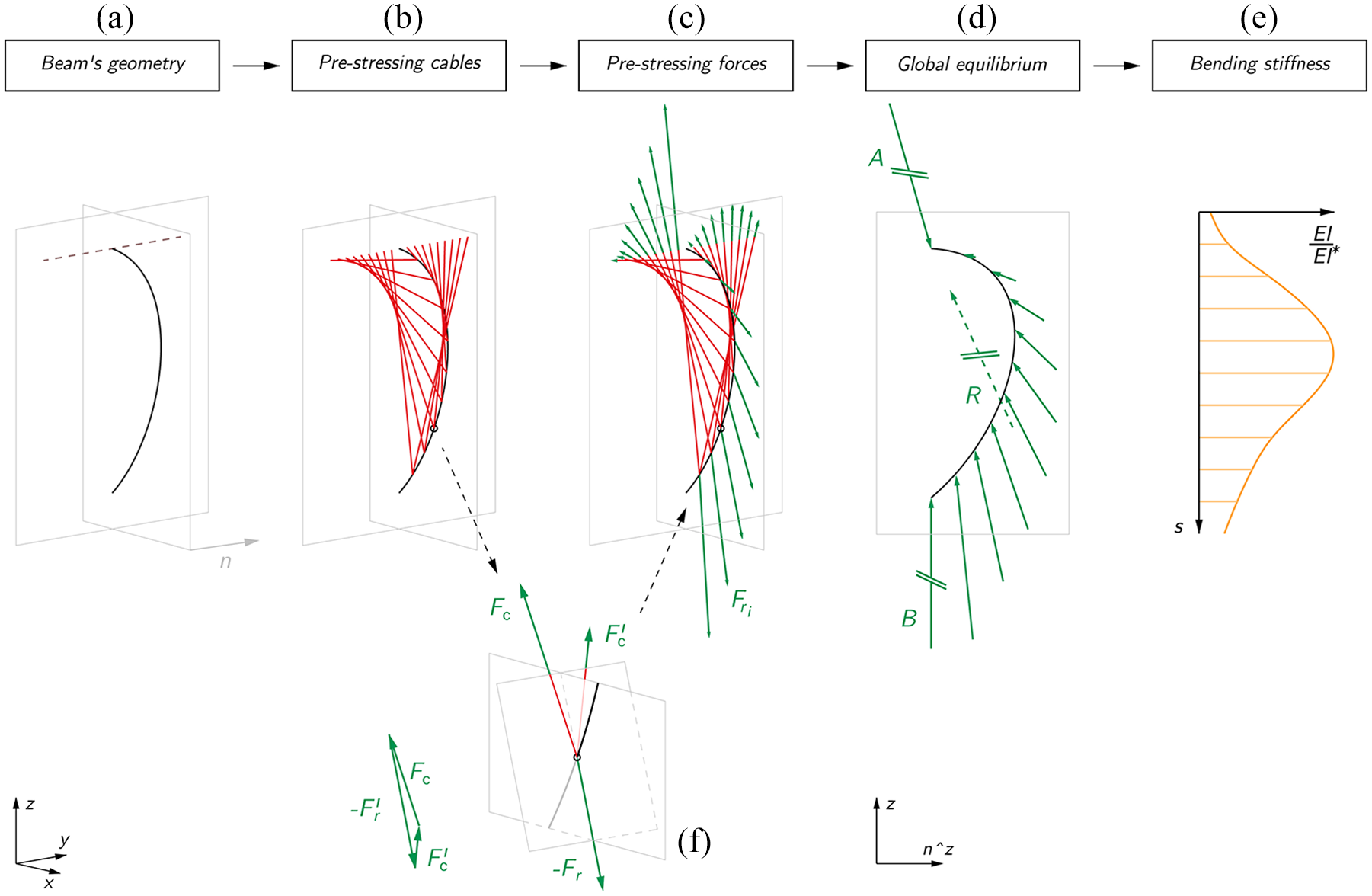
Design process based on the form-driven approach to bending-active tensile systems: (a) definition of the beam’s geometry as planar curve, (b) generation of a compatible prestressing cables, (c) definition of the pre-stressing-forces, (d) evaluation of the beam’s global equilibrium and (e) bending stiffness distribution along the beam’s axis.
Based on the new geometric procedure introduced in this article, for each node of the beam to be restrained, two straight pre-stressing cables are introduced that connect the actively bent beam to their neighbouring beams or to the system’s boundaries (Figure 3(b) and (c)). The pre-stressing forces

where
As a result, the form-driven design approach, strengthened by additional geometrical rules on the tensile elements, creates a design framework that allows the geometrical exploration of multiple hybrid systems.
Integral design framework
Within its scope of applicability, the form-driven approach as described above allows decoupling the generation of the geometry of a bending-active tensile system from the assessment of its static equilibrium. This makes it possible to first focus on the generation of feasible hybrid structures whose shape can be easily controlled and adjusted according to geometry-dependent criteria, before integrating further structural and manufacturing aspects into the design. Figure 4 summarizes the integral design framework described above, which relies on the use of a parametric model. This is made of three different sub-models: the first one (geometric parametric model – section ‘Parametric geometric model’) defines the geometry of the bending-active tensile system, the second one (structural parametric model – section ‘Parametric structural model’) performs the structural evaluation and the last one (manufacturing parametric model – section ‘Parametric manufacturing model’) addresses questions related to fabrication.
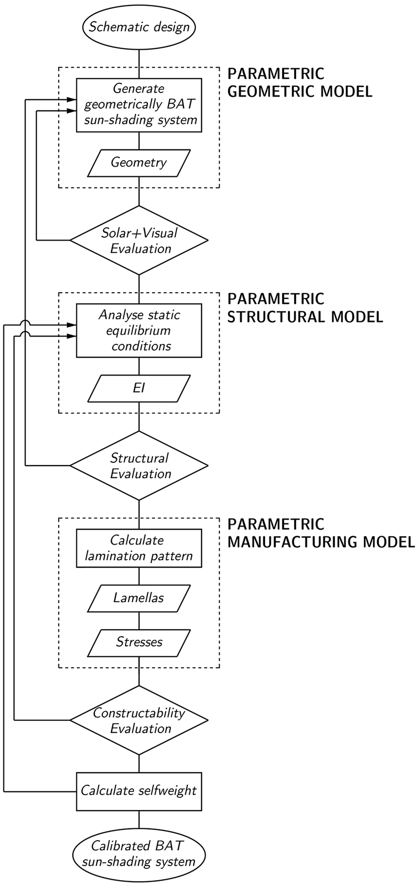
Integral design framework based on three different parametric models.
Design of the bending-active tensile sun-shading system
The design of a sun-shading system that protects a glazed building façade should respond to sometimes contradictory requirements for the thermal and visual comfort of the building’s occupants. On the one hand, the solar gain through direct sun exposure of the façade should be reduced during summer and to a less extent, over spring and autumn, to prevent the internal overheating of the building and to reduce the energy consumption of active cooling systems. Moreover, during winter, daylight glare discomfort of the building’s occupants caused by the low position of the sun in the sky should be eliminated. On the other hand, the visual comfort of the building’s occupants should be satisfied throughout the year, by preserving as much as possible suitable lighting conditions as well as the views to the outside offered by the glazed façade.
Description of the case study and definition of the indoor comfort evaluation criteria
The sun-shading façade system used as a case study in this work has been designed for an office building located in Zurich (Switzerland) at the ETH Science City Campus. The building consists of a main volume containing office spaces, sitting on top of a smaller volume with workshops and technical rooms. At present, the building lacks an external sun-shading system. Considering the orientation of the building and the fact that the surrounding buildings naturally generate shadow, the most exposed façades of the building that require sun protection are the south-west façade and part of the south-east one (Figure 5). The indoor zones located behind the exposed façades are distributed on two floors and consist of one circulation space and two different workspaces (Figure 6).
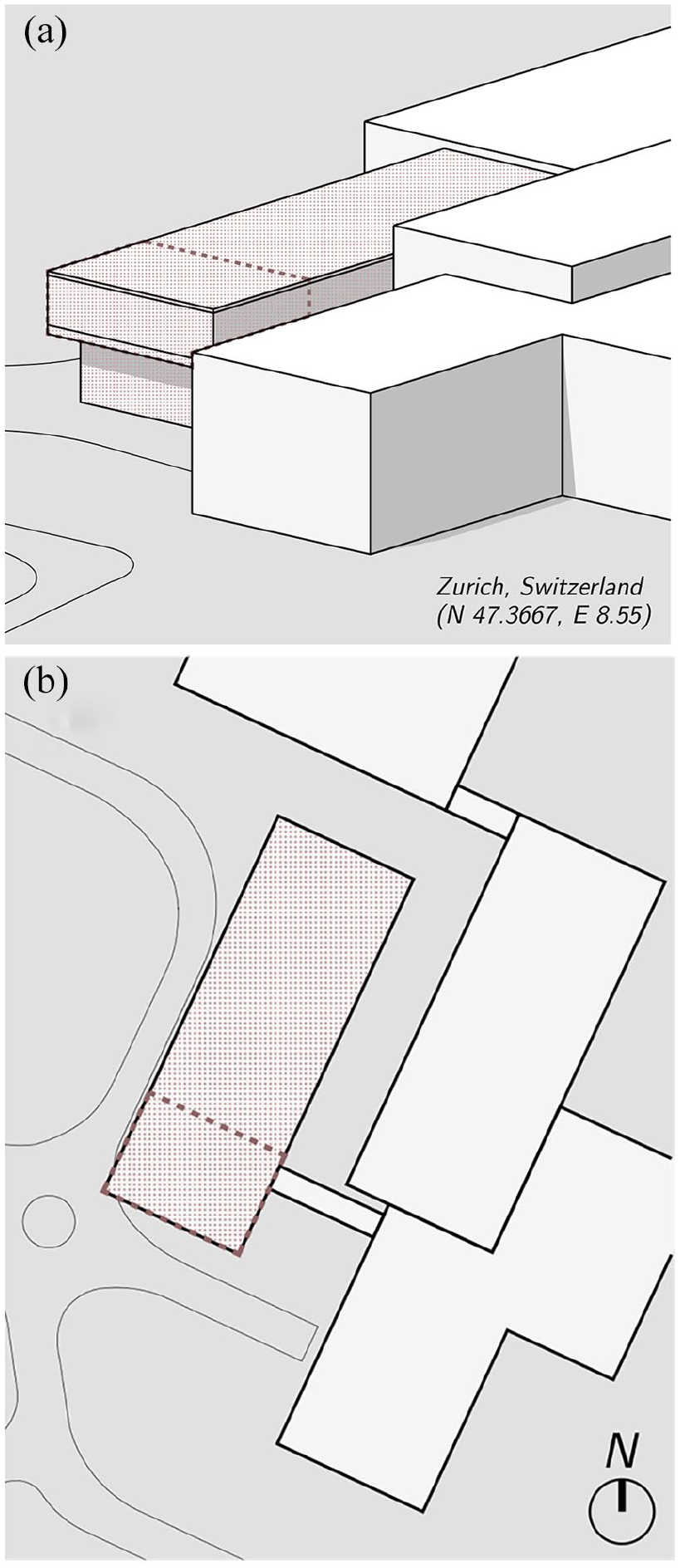
Situation of the office building chosen as a case study: (a) axonometric view and (b) top view.

Solar and visual analysis and design development: current state (case 0) and design variations (cases 1.b to 3.d).
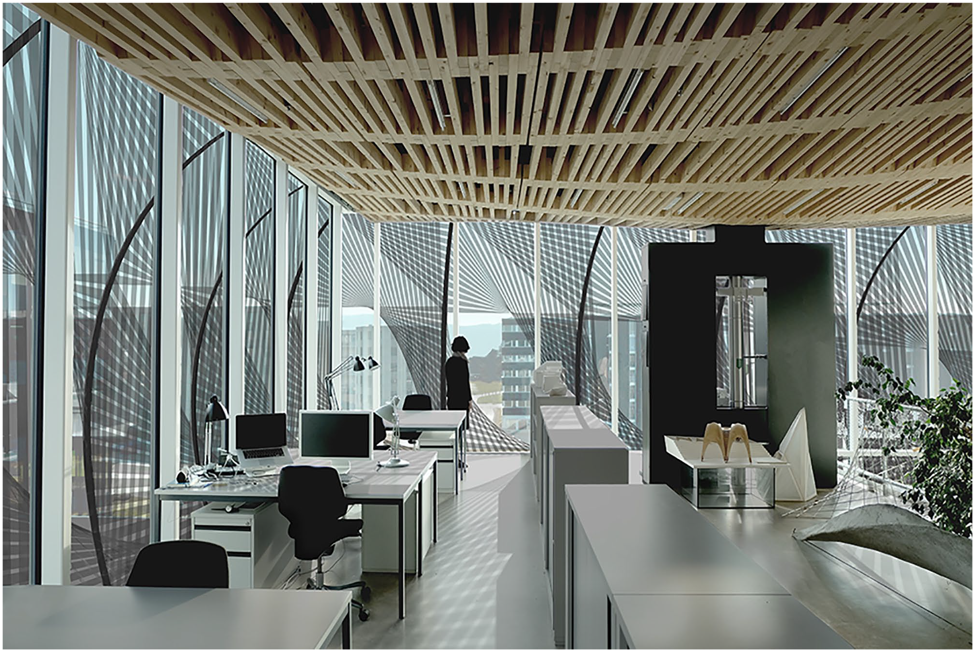
Interior view of the office with the proposed sun-shading system applied on the façade.
To evaluate the indoor comfort of the building’s occupants, several evaluation criteria were defined in relation to thermal, lighting and visual connectivity aspects. Since the thermal comfort in an indoor space strongly depends on the amount of solar radiation that enters the building through its façades, the related metric which was considered is the following:
Solar radiation (kWh): The total incident direct solar radiation received by the glazed façades over a day.
Regarding the indoor visual comfort, three different aspects were considered: the illuminance level, the risk of glare and the visual connection to the outside. They are, respectively, evaluated according to the following metrics:
Illuminance level (h): The average time of a working day (9am–6pm) for which the illuminance value (lux) of an ideal horizontal work plane, positioned at 0.9 m above the floor, remains within the acceptable range of 100–3000 lux; 32
Glare level (h): The average time of a working day (9am–6pm) for which an ideal horizontal work plane, positioned at 0.9 m above the floor, is under direct sunlight. This measure is directly related to the glare risk;
Visual occlusion level (%): The percentage of visual occlusion of the horizon surface from a grid of points inside the building located 1.2 m above the floor, which corresponds to an ideal eye height when sitting.
The metrics were assessed for the different indoor zones with the Grasshopper’s 33 plug-in, Ladybug 34 in the Rhinoceros CAD environment 19 (Figure presents the average values over the calculation 6 presents the average values over the calculation area). The solar analysis of the building in its current configuration – without sun-shading system – allowed clarifying the needs of the building in terms of solar protection, and in particular, to identify the most critical times of the year and of the day when major indoor discomfort occurs. It helped to initialize the step-by-step design development presented below. Above all, it served as a reference to weigh the benefits brought by the distinct sun-shading systems explored below in relation to the considered metrics.
Design development
The shape of the bending-active tensile sun-shading structure to retrofit the previously described building has been obtained through successive transformations of a generic sun-shading system, considering the above thermal and lighting criteria. Through this progressive geometric definition, starting from simple configurations, the complexity of the structure has been gradually increased in iterative steps and new geometric parameters have been introduced (Figure 6). The following paragraphs offer an overview of this parametric study, while a complete description of the parametric model used in Step 3 is presented in section ‘Parametric geometric model’.
Step 1: combination of horizontal and vertical brise-soleils
In the first step, different modular configurations, combining conventional vertical and horizontal rectangular brise-soleils, were explored to assess the general dimensions of the structure – that is, the relative spacing, depth and orientation of the sun-shading elements (Figure 6, cases 1.a and 1.b).
Step 2: introduction of curved sun-shading elements in place of the vertical brise-soleils
In the second step, the vertical brise-soleils were replaced by curved sun-shading elements. The upper horizontal sun-shading elements were then adjusted accordingly. An investigation was conducted to determine the geometry of the curved elements that contribute the greatest to the reduction of the solar radiation on the façade and the risk of glare (Figure 6, cases 2.a and 2.b).
Step 3: transition to a bending-active tensile system
In the third step, the geometry resulting from the previous step was modelled in the form of a bending-active tensile structure following the rules presented in section ‘Design of the bending-active tensile sun-shading system’. To simplify the calculations, the tensile elements were replaced with a continuous ruled surface. Multiple parameters were used to describe the geometry of the sun-shading structure (section ‘Parametric geometric model’), and different variations of these parameters were tested to produce various spatial configurations, such as those ones in Figure 6. At last, additional parameters were introduced to enable the top-down control of the global geometry of the sun-shading structure at the building scale, and thus break the modularity of the structure. This additional differentiation of the system allowed for a better negotiation of the different design requirements. Moreover, the above continuous ruled surfaces were replaced with wide strips, whose widths were adjusted to balance the conflicting requirements for sun protection and internal illuminance level.
Design outcome
Through geometric variations along the two façades of the building, the designed bending-active tensile sun-shading façade system offers a global solution to a time-dependent issue. The different requirements in terms of visual and thermal comfort, which are sometimes conflicting over time, are negotiated through an appropriate geometry of the system. In particular, the proposed structure is more open at the level of the workspaces to maximize the visual connection of the occupants to the outside while preventing the risk of glare. On the contrary, in other parts of the façade, particularly on the south-western side where the corridors are located, the structure is more closed. From a structural standpoint, neighbouring beams are interconnected with the sun-shading strips that work in tension, overall generating a continuous system along the façades.
In relation to the considered indoor comfort evaluation criteria, the designed sun-shading façade system performs in a similar manner as conventional sun-shading configurations (as case 1.a and 1.b). However, in the proposed system, unlike in conventional systems, the structure and the sun-shading function are fully integrated. The sun-shading tensile strips unfolding on either side of the beams are structurally active and offer an integrated solution for wind bracing, while the resort to discrete cables decreases the system’s windage. The resort to active bending allows to activate thin sections of material.
Parametric models
As explained in section ‘Integral design framework’, the integral design framework involves three different parametric models, which are detailed below.
Parametric geometric model
In accordance with section ‘Form-driven approach’, each actively bent beam and the related tensile elements (beam-cables cluster) are defined geometrically one after the other and can be adjusted any of the two at any time.
Figure 8(a) shows the different geometric parameters involved in the generation of the bending-active beams. The planes where the beams’ axes are located are oriented with an angle
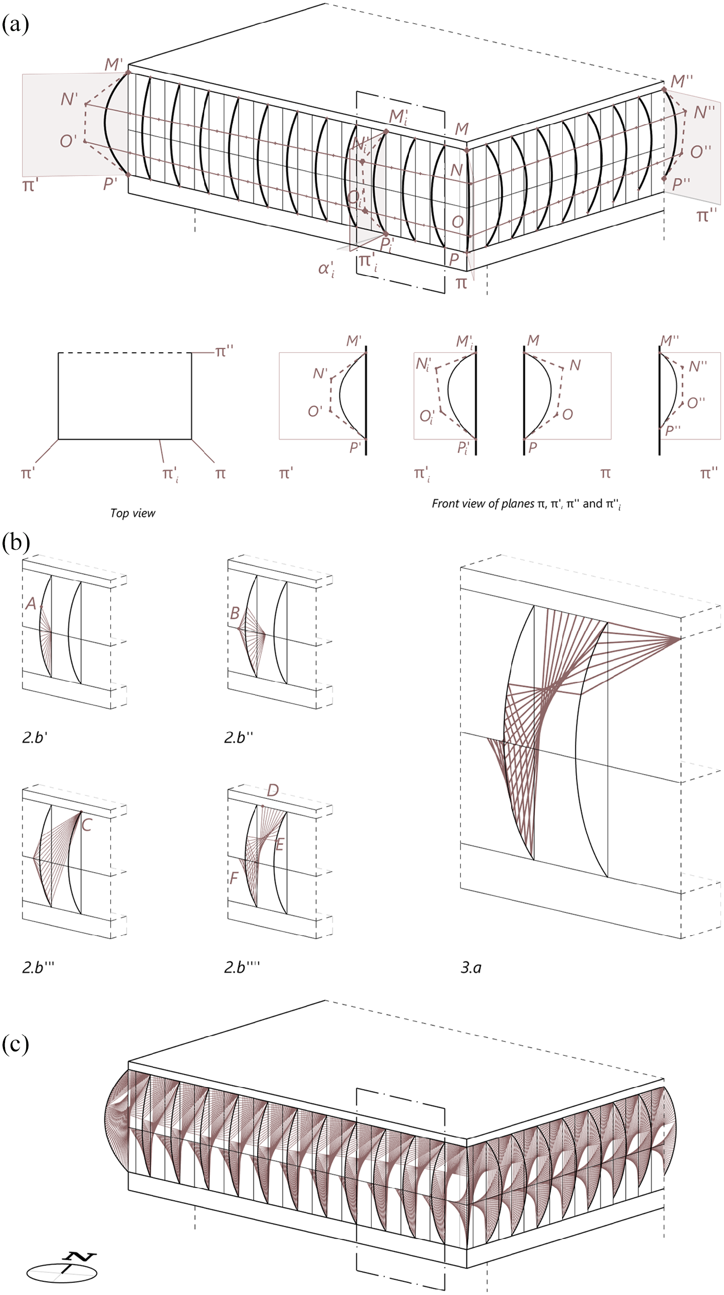
Parametric geometric model. (a) Parametric definition of the actively bent beams as NURBS curves. (b) Generation of the parametric volumetric tensile sun-shading sub-system, from a planar configuration and preserving the planar static equilibrium of the beams. (c) Final geometry of the bending-active tensile sun-shading structure obtained thanks to the global parametric geometric model.
As for the straight cables, they are geometrically arranged in space to reproduce the global geometrical features of sun-shading configuration 2.b, as it was found to be a satisfying solution with regards to the considered thermal and lighting metrics. The spatial layout of the cables emerges from the progressive transformation of a simple planar system consisting of a beam restrained with radial cables as detailed in Figure 8(b) while preserving the conditions for a 2D equilibrium of the beams. For each cluster, the position of points
Finally, the parameters related to both the beams and the cable layouts are integrated, resulting in the complete geometric model of the sun-shading structure (Figure 8(c)). Global and local parametric variations can then be implemented.
Parametric structural model
Once the overall system geometry is established, pre-stressing forces are assigned to the cables. Given the relation of equilibrium (1), for each two cables connected to a node of the beam, a pre-stressing force
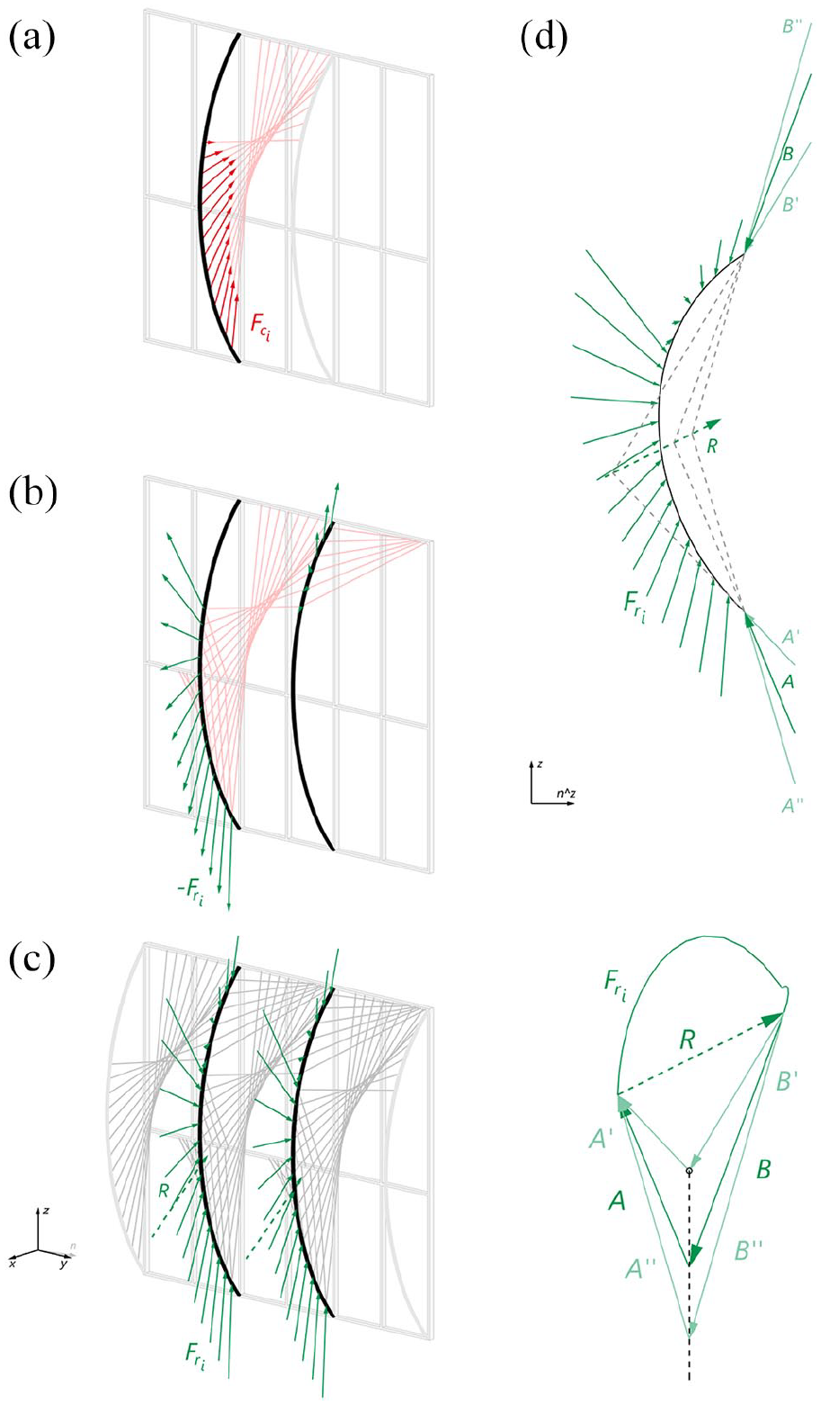
Structural evaluation of the hybrid system. (a) Assignment of pre-stressing forces in the cables. (b)–(c) Calculation of restraining forces. (d) Solving of global equilibrium through reaction forces.
Finally, for each beam, a non-constant bending stiffness is determined according to the graphical method proposed by Boulic and Schwartz, 3 in such a way that the beam bends into the previously defined equilibrium geometry under the action of the previously defined pre-stressing loads (Figure 10(b)).
Manufacturing parametric model – parametric generation of lamination patterns for producing beams with variable bending stiffness along their axis: (a) external forces applied to the beam, (b) bending stiffness distribution along the beam’s axis and (c) possible beam’s cross sections based on different lamination patterns.
Parametric manufacturing model
The calculated bending stiffness EI is not constant and varies along the axis of the beam. Since a differentiation of the elastic modulus E along the beam is rather difficult to implement even if possible, 29 such variations are obtained here by tailoring the geometry of its cross-section and thus the moment of inertia I along the bending axis. One possible way to produce beams with variable cross-sectional areas is to laminate the beams out of individual elastic lamellas, with variable width and length but constant mechanical properties. To keep the position of the main axis of inertia constant, the lamellas are assembled symmetrically with respect to the axis of the beam. For example, in the case of a section composed of five symmetrical layers (Figure 10(c)), the quadratic moment is given by the following formula

where

Different lamination configurations can produce the same quadratic moment of inertia because for a given number of lamellas of known thickness, there is infinity of widths
Material investigation and fabrication of a 1:2 scale prototype
Structural prototype
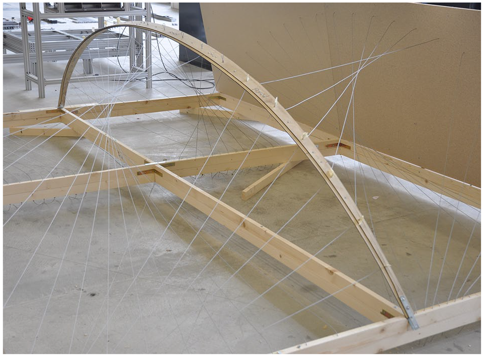
A prototype of the sun-shading structure was built at 1:2 scale to provide a qualitative validation of the design method and the structural model and to check its applicability to a real construction. A representative portion of the entire bending-active tensile structure, which was made of four actively bent beams, was built (Figure 14). The beams at the sides of the prototype have been materialized in the form of rigid frames.
Fabrication of beams with variable bending stiffness
Plywood lamellas
A 1-mm thick birch plywood made of three plies was chosen for the lamellas in the laminated beams. Due to its high flexural strength and its moderate stiffness, plywood is an ideal material to resist large elastic displacements without failing, 35 thus appropriate for the realization of bending-active structures.29,36–40
The mechanical characteristics of the chosen 1-mm thick birch plywood have been estimated by simple mechanical tests. A series of plywood lamellas (width b: 40 mm, length l: 1000 mm, thickness e: 1 mm), with their longitudinal axis aligned with the grain direction of the outer plies, were bent with a cable into different Elastica, and the corresponding buckling force was measured. From these measures and based on the theoretical values of the buckling force/bending stiffness ratio,
41
the average elastic modulus

Simple physical tests to characterize the mechanical properties of 1-mm thick birch plywood lamella. (a) Estimation of the modulus of elasticity. (b) Estimation of the yield strength. (c) Additional converging 3-point bending test to estimate the modulus of elasticity.
Fabrication of laminated beams
With regard to the manufacturing of the different lamellas, there were laser cut from panels of the above 1-mm thick plywood. Due to the limited bed size of the laser cutter, the lamellas had to be segmented into shorter elements, which were subsequently glued and mechanically connected (Figure 12(a)). Joints with a dovetail geometry were used to ensure the transfer of tensile forces within the bent beams, while the transfer of compressive forces was ensured by contact between the lamellas’ segments. The behaviour of the joints as a function of their geometry and their distribution in the beam was studied through a series of physical tests. From one lamella to another, the discontinuities caused by the joints were shifted to avoid the generation of mechanical weakness along the beam (Figure 12(a)). The use of mechanical fasteners prevented the delamination of the lamellas in the most critical areas, whether under compression or tension.

Laminated beams. (a) Assembly logic of a laminated beam from segmented lamellas. (b) Laminated beam cross-section.(c) Pattern of the constituting lamellas.
Steel cables
In the prototype, the tensile elements, representing the sun-shading strips, were materialized as steel cables. In addition, at this stage of the design process, the elongation of metal cables was negligible, whereas the use of a textile material, for example, would require a more in-depth knowledge of its mechanical properties. The length of the cables was controlled by shaft collars.
Calibration of restraining forces and lamellas pattern according to mechanical properties
The calibration of the internal forces within the structure has been carried out over four successive steps as depicted in the flow chart of Figure 4 (analysis of structural equilibrium, calculation of number of lamellas in the beam, generation of lamination pattern and integration of self-weight in the calculation) and has involved both material and fabrication-related parameters.
Pre-stressing forces and reaction forces were adjusted in such a way that the cables were stretched evenly, the internal stresses remained within the allowed values and the shape of the different lamellas satisfied the fabrication requirements.
Regarding the determination of the number of lamellas constituting each of the different beams, this value has been calculated so that the axial stress in the beam reaches at maximum 75% of the material maximal capacity. In this way, the beam gains enough stiffness through the pre-stressing effect of active bending without risking material failure. Given a beam under pure flexural bending in the

The normal stress acting on the beam’s cross-section is given by
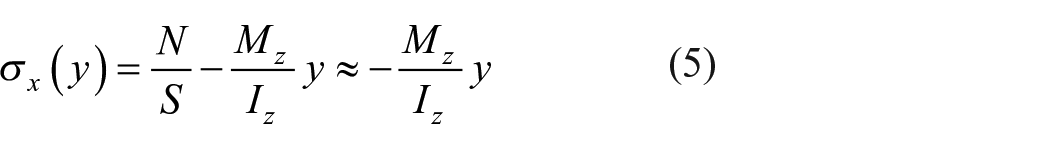
After substitution, it simplifies to

which leads to the maximal value of the normal stress in the beam

The thickness of each beam, therefore the number of lamellae which are layered, is calculated as such
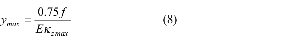
In the case of the two beams of the prototype, this gives, respectively, a beam height of 9.5 and 9.9 mm that correspond in both beams to 9 lamellas of 1 mm of thickness (Figure 12(b)).
Finally, the self-weight of the beam was introduced in the calculation based on a material density of the plywood lamellas of 650 kg/m3. The four above steps were repeated until the dimensions of the beam cross-section converge to a unique configuration (Figure 13). Ultimately, the lamination pattern of each beam could be produced and the lamellas laser cut (Figure 12(c)).

Integration of self-weight effect in the beam’s bending stiffness calculation.
Prototype assembly
A timber frame was first built to replicate the curtain wall of the façade. Once manufactured according to the lamination patterns, the two beams were progressively and slowly bent until their extremes could be connected to the frame on free rotating supports. As the deflection was increasing, water was spread several times onto the stretched face of the beams to release stresses and prevent failure. Afterward, all the cables have been connected loosely to the beams and the frame, and the cables providing the strongest restraining forces were adjusted first (Figure 15). Iteratively, the length of all the cables was adjusted until the required pre-stressing force was achieved. The staggered positioning of the joints within the different laminates of the beams allowed for a smooth curvature of the bent elements (Figure 16).
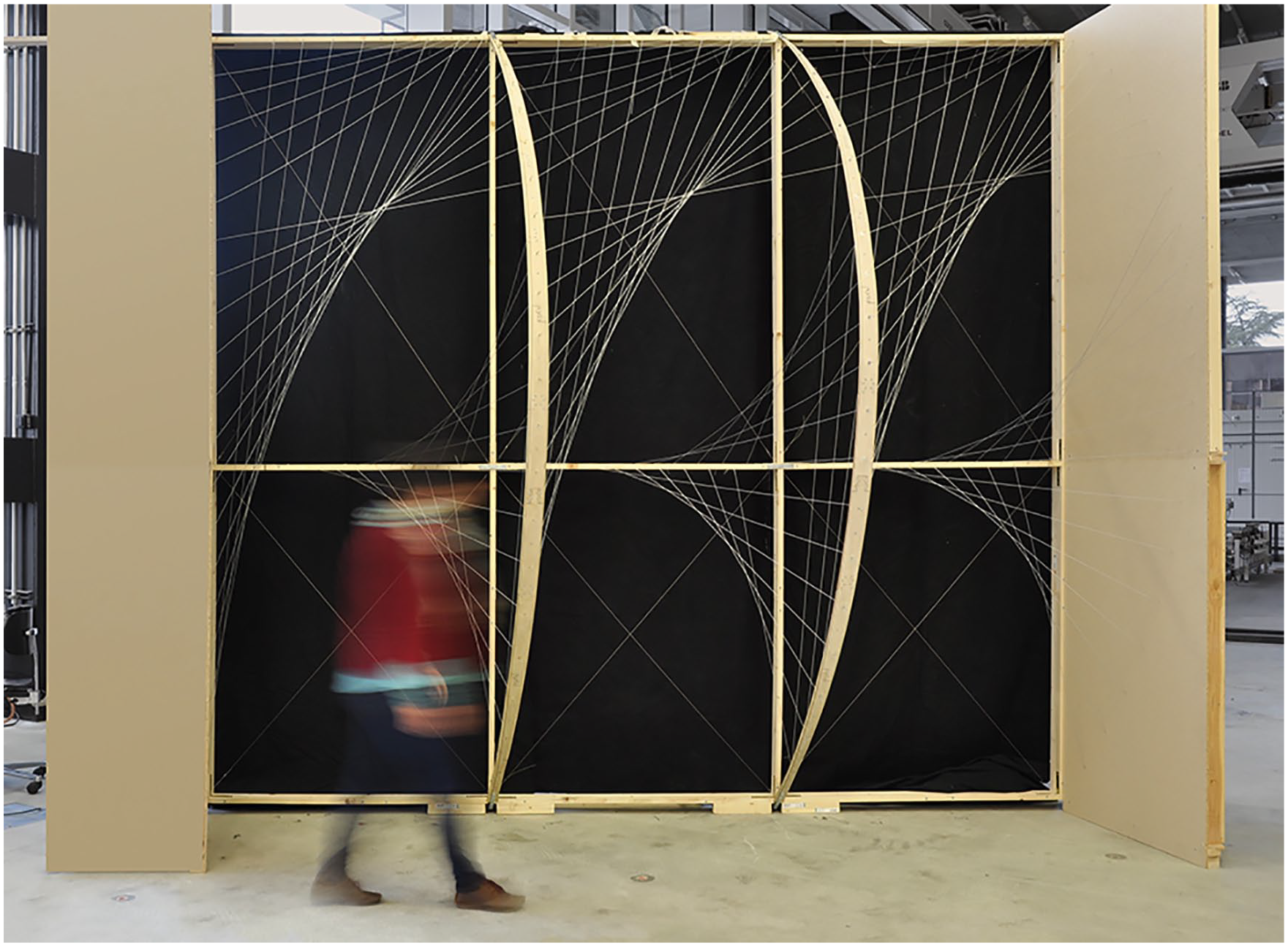
1:2-scale structural prototype of a representative portion of the sun-shading structure.
Assembly process.
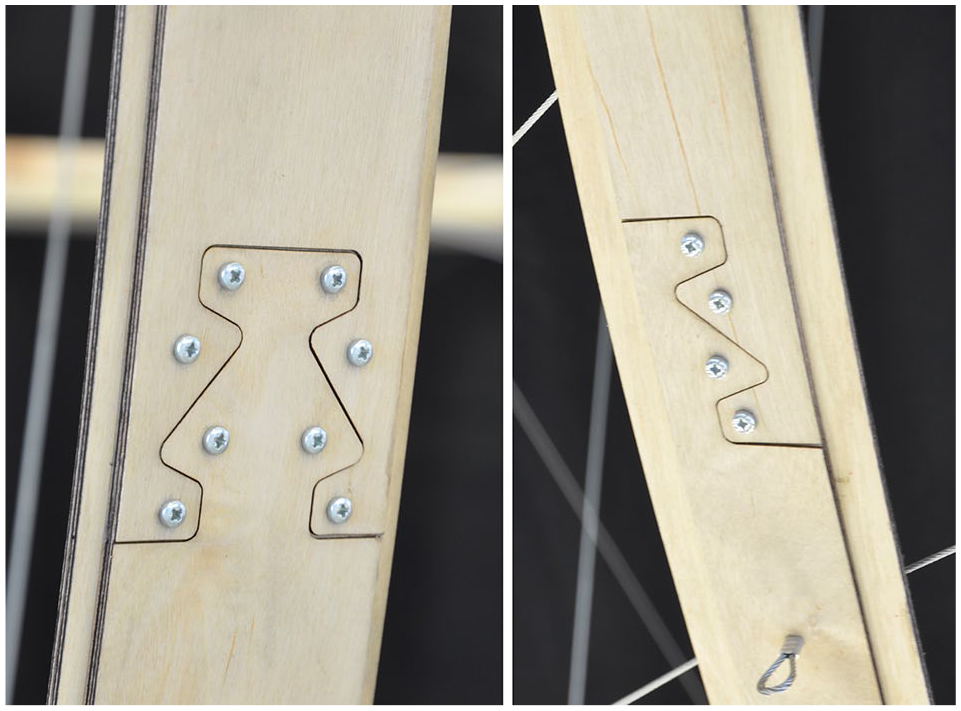
Details of the joints between the segmented lamellas.
Discussion and conclusion
Through the exemplary design of a façade sun-shading system, it has been demonstrated how the proposed form-driven approach to bending-active tensile systems, 3 unlike conventional form-finding methods, allows having explicit control over the equilibrium geometry of the hybrid system. Such direct geometric control is particularly beneficial in those design applications in which structure is not the only parameters to be considered but also architectural, environmental and manufacturing considerations are at stake. Thanks to the form-driven approach, an integral design framework which includes all these aspects has been proposed based on a parametric geometry-based definition of the bending-active tensile structure. Eventually, through the variation of the system’s geometry along the façades and the variation of the beams’ bending stiffness along their axis, a negotiation between all the parameters that influence the geometry of the system has been possible.
Further considerations can be made in relation to the effectiveness of the design process. In particular, throughout the process, various parameters were adjusted manually. One could imagine an automation of the process to refine the distribution of pre-stressing forces and internal stresses in the system and to consider manufacturing constraints. Besides, finite element analysis would be helpful in assessing the behaviour of the system more thoroughly, after its geometry has been designed using the form-driven approach.
The structural prototype established a first step towards the development of a complete façade system, and it provided valuable information regarding the forces calibration procedure. The fabrication of the prototype gave a first qualitative validation of the theoretical digital model, although a more thorough assessment of the physical model would be required to draw a deeper conclusion.
With regards to the fabrication itself, further developments should be implemented. On the one hand, the current pre-stressing steel cables, which are supposed to work as sun-louvers, should be substituted by tensile strips, such as coated fabric strips. The possibility to slightly stretch the material would facilitate the tensioning of the tensile elements. On the other hand, further research is required to defined a proper material system that can be effectively used for the manufacturing of the beams at full scale. Composite materials and industrial lamination manufacturing processes could be explored to improve the fabrication of beams with non-constant bending stiffness along their length and avoid the resort to mechanical joints and fasteners.
Footnotes
Acknowledgements
The authors thank Alessandro Tellini and Denizay Apusoglu from the Rapid Prototype Laboratory (Raplab) at ETH Zürich, who provided support during the development of the experiments and the manufacturing of the prototype, and Artai Sanchez for his help with the visualizations.
Authors’ Note
LB, PD, FB received salaries from ETH Zurich and JJC received salary from Rice University.
Declaration of conflicting interests
The author(s) declared no potential conflicts of interest with respect to the research, authorship, and/or publication of this article.
Funding
The author(s) received no financial support for the research, authorship, and/or publication of this article.