
Abstract
Mesh reflectors are always a preferable option for large size deployable antenna reflector over solid surface reflectors due to their flexibility of adjustment in minimum possible space and ability to get deployed to full configuration in space. Maintaining surface properties and accuracy are two important requirements in the design of the mesh reflector for the performance of cable network antenna reflectors. The present work considers the various design approaches for cable mesh configuration of space deployable antenna reflectors. The equal force density shape forming criteria such is applied for obtaining the desired parabolic curvature of the mesh configuration. The ring structure for the deployable mechanism is considered as rigid linkages for designing mesh configuration. A generalized numbering scheme for nodes and cable mesh link is formulated for carrying forward various shapes forming criteria which help in making an algorithm. The algorithm for a better understanding of these methods is developed using MATLAB with nodal coordinates and its connection. Mesh configuration is developed with a different number of divisions. A study is also carried out for finding the required number of divisions for a highly accurate parabolic profile for a particular band frequency. A demonstration model is developed and a comparison of the coordinates of the prototype is made with those arrived at using the model.
Introduction
The deployable mesh antenna reflectors have their applications in a wide area such as remote sensing, satellite communication, earth observation, etc. A mesh antenna uses a reflective mesh surface to reflect electromagnetic radiation. 1 Space mesh reflectors are made of the metallic mesh. The mesh reflector antenna should meet the requirements of the microwave electrical property, the mechanical property, the anti-bulking property and the wrinkle resistance property. There are some challenges to the cable mesh antenna such as the accuracy of reflecting surface, the precision of deployment, dimensional stability of material and structure. Many factors affect the microwave electrical properties of the cable mesh, such as material properties and woven structural openings. Mesh materials generally used worldwide are molybdenum, stainless steel, and tungsten with a nickel-plated or gold-plated surface. 2 A cable network for an astromesh deployable antenna reflector is considered for investigation which consists of a front net, rear net, reflective mesh, tension ties, and supporting truss. 3 The front and rear nets are attached to the deployable ring truss. The front net plays the role of supporting the metal RF reflective mesh and the rear net is used to balance the tension. The tension ties can be adjusted to control the shape of the metal reflecting surface.
For concentrating radio frequency (RF) radiation, the working surface of the cable network antenna reflector needs to maintain a perfect paraboloid shape, which is determined by the mesh shape of the cable network antenna reflector. The performance of the cable network antenna reflector highly depends on the well-designed mesh configuration. In recent years, various researchers have proposed the design of a feasible mesh configuration of the cable network antenna. Yang et al. 4 proposed a meshing procedure in which the aperture plane of a paraboloid is divided into six equal parts to form a hexagon and further subdivided into an equal triangle. Liu et al. 5 presented a different method for the division of the surface of the mesh reflector such as cyclosymmetry method, sub-region division method and topological mapping method. The cyclosymmetry method is explored with a triangular faceted configuration to get maximum fill factor. Tibert 6 presented an optimal design approach to generate minimal length mesh configurations for tension truss antennas. The author presented several methods for form finding of mesh reflectors such as a force density method, nonlinear finite element method, and two-step form finding method. The main objective of this study was to investigate a simple and practical method for the mesh design of cable-network antenna reflectors. Xiaofei et al. 7 presented various methods for form finding such as force density and nonlinear finite element method. Liu et al. 8 proposed an approach that includes standard FEM with the conventional force density method in which elastic deformation of ring truss was included. This method can produce an exact parabolic shape which can satisfy the requirement that all free nodes are located on the parabolic surface. Yang and Yang 9 presented a novel method in which initially the front net is designed with the combination of force density and surface stress density method from which they get uniform cable tension and membrane stress of the front net. Scialino et al. 10 offered a numerical model based on a condensed simplification of a mesh element by using springs and nodes for simulating the structural behavior of the mesh. Datashvili and Baier 11 proposed the shell-membrane technology based on carbon fiber reinforced silicone composite material which has a high potential for mass and cost efficient solutions.
Configuration approaches
Among various mesh configurations of deployable antenna reflectors available in the literature, astromesh configuration is taken into consideration for investigating mesh design. Though, it would be equally applicable to other design configurations also. The astromesh configuration consists of two parabola front and rear nets connected with variable tension ties for controlling the shape of a paraboloid for maximum RF gain. To formulate a parabolic profile over mesh configuration, force density and equal force density methods 12 are explored. The front net and the rear net of the cable-network antenna reflector are identical, the shape-forming procedure can be performed simply on the spatial mesh of the front net, while the vertical forces applied by the tension ties can be treated as the external loads directly exerting on the cable mesh.
Force density criteria
The force density method was first proposed by Wang, 13 which is frequently used for form finding of cable and membrane structures. The key feature of this method is that it converts the nonlinear nodal equilibrium equation into linear by varying force densities. Force density is a ratio of force to element length. The force density method provides the geometric configuration with tension distribution and nodal displacement. The cable network structure has fixed nodes that are connected to supporting truss and free nodes which are not constrained as shown in Figure 1.
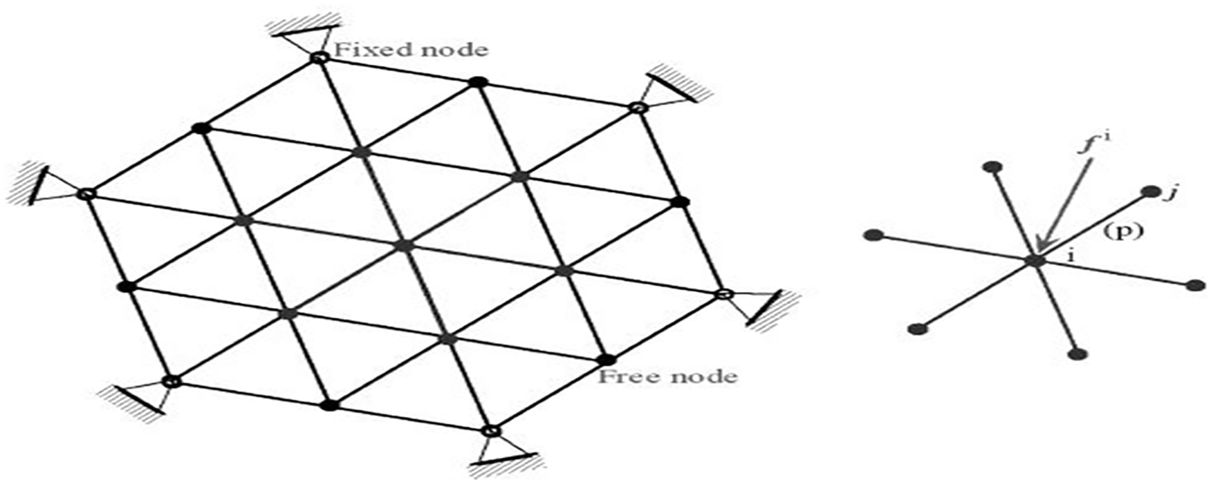
Typical cable network structure with fixed and free nodes.
If in cable structure, the total number of cables are m, free nodes are
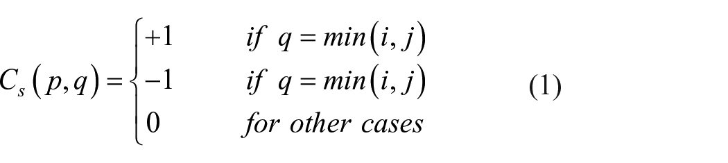
where element p matches with node i and node j.
For simplicity, free nodes can be inserted at starting while fixed nodes can be inserted at the end so topological matrix can be rewritten as:
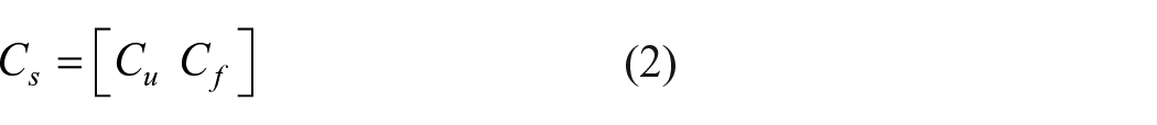
where
For an arbitrary node i equilibrium equation for this node can be given as:
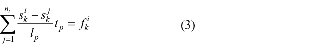
where
Equation (3) is nonlinear because length

where
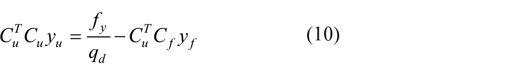
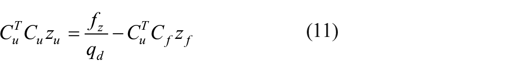
The general formulas of the force density method to calculate free node coordinate are given by:


where,
The cable network antenna has a paraboloid reflective surface so all the free nodes can be located on a paraboloid by the following equation:
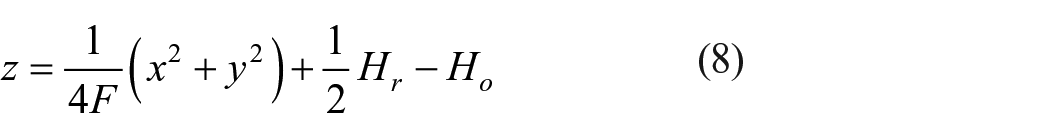
where F is the focal length,
The tension of vertical cables is considered as external forces which are applied on the cable net. So in equations (5) to (8)
Equal force density criteria
If all the cables in cable network have equal force density ratio

Methodology for determination of configuration
The numbering scheme, surface error and configuration of the large deployable antenna are presented in this section.
Numbering scheme proposed
Numbering Scheme for cables and nodes defined for force density method in the literature are in random order. In the present study, the numbering scheme is proposed in a sequential and systematic order which reduces programming efforts of recording nodal coordinates and reducing computational time. All cables and nodes are numbered in a counterclockwise direction from inner to outer. The numbering scheme for the N = 3 division is shown in Figure 2.
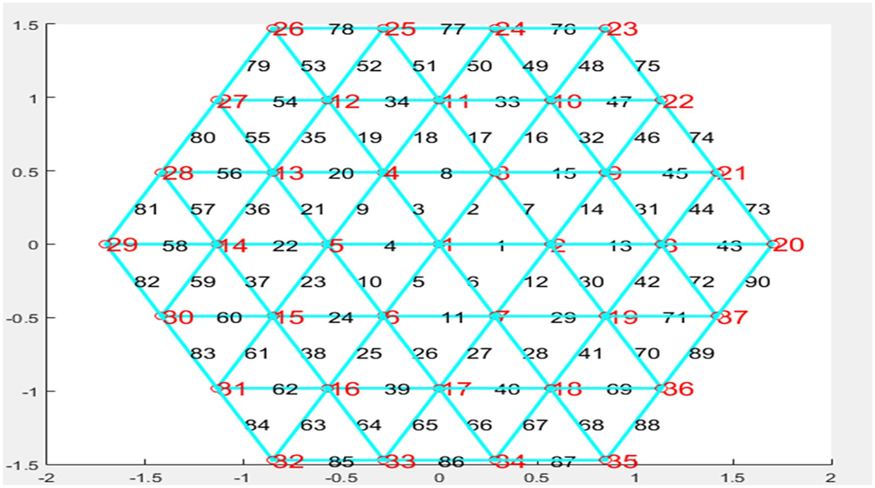
Numbering scheme for N = 3 division.
The assembled matrix, in both cases that is random numbering order and sequential and systematic numbering order is symmetric. Thus, the demands on computer storage can be substantially reduced by storing only the elements involved in half bandwidth instead of storing the whole matrix. All the nonzero coefficients in case of sequential and systematic numbering order are clustered around the leading diagonal, while nonzero coefficients are all well spread out in case of random numbering order. At the time of implementation of typical Gauss elimination to solve the matrices, most of zero coefficients remain zero throughout the solution process in case of sequential and systematic numbering order. Thus there is no reason to even store them, which saves further valuable computer memory. It is usually a simple computer program that relates these coefficients to their appropriate locations in the full or global matrix. Node numbering, therefore, has a significant effect on the distribution of zero and nonzero coefficients in the global matrix, and efficient node numbering schemes are an integral part of any pre-processor used for complex real-life problems.
Prediction of surface contour
The surface of the cable-network reflector is approximated by interconnected polygonal facets for making the paraboloid shape. The shape of the realizing mesh reflector would cater to a certain deviation from the ideal parabolic surface due to present an approximation of polygonal facets. The deviation, caused by the faceting design, is called the geometrical faceting error. The surface deviation can be found by equation (12).
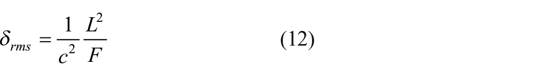
where L is a length of the side of polygon facet, F is a focal length and c is a constant equal to 7.872 for the triangular faceted mesh. 14
Astromesh antenna 3.4 m configuration
Feasibility study of the concept is applied to an astromesh concept of 3.4 m diameter size with 12 polygon ring truss which is shown in Figure 3.

Mesh configuration of 12-bay, 3.4 m antenna reflector.
The specifications of the antenna reflector used for numerical simulation are as follows:
Antenna maximum aperture: 3.4 m
Focal length: 1.72 m
Height of reflector: 0.4200 m
Antenna operating frequency: S-band
Number of ring truss: 12
Mesh facet type: Triangular
Shape design criterion: Force density and equal force density
Design value of surface accuracy: 3 mm
Triangular faceted mesh configuration
The triangular faceted mesh configuration is generally used because it gives a good distribution of mesh compared to other quadrangle and hexagonal faceted mesh configuration. Quadrangle and hexagonal mesh configuration give inferior tension distribution compared to triangular faceted mesh configuration.
13
Here, the design approach is applied to generate triangular faceted mesh configuration in numerical simulation. By applying various shape design criteria, a specific mesh configuration is obtained using MATLAB. By applying force density criteria for a given configuration of deployable space antenna reflector a paraboloid mesh configuration, various parameters such as the number of division, number of cables, maximum and minimum tension, mean length of cables and faceting error are derived which are presented in Table 1. Force distribution for N = 3 in cables due to tension tie load is shown in Figure 4. Similarly, equal force density criteria are applied for 3.4 m astromesh antenna with force density
Results of triangular faceted mesh configuration with force density criteria.

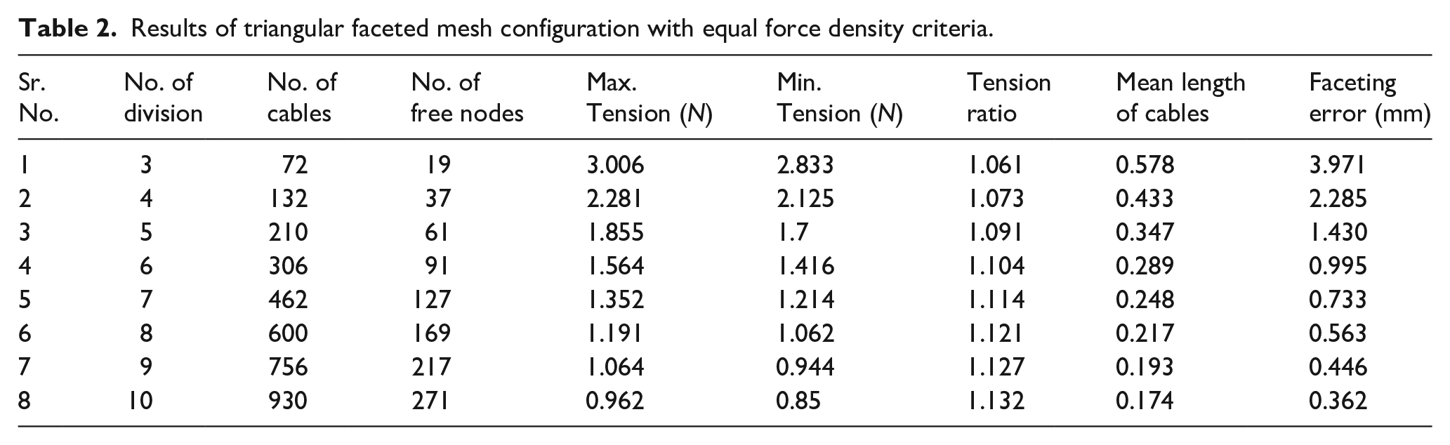
Results of triangular faceted mesh configuration with equal force density criteria.

Force distribution in cables due to tension tie loads with force density criteria for N = 3.
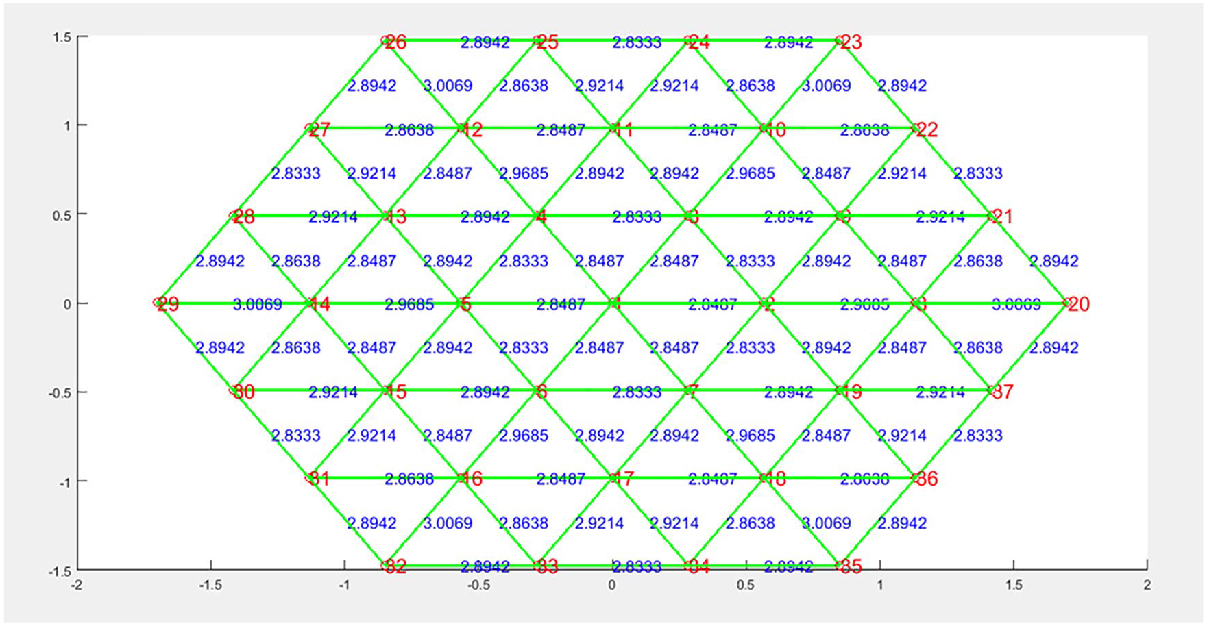
Force distribution in cables due to tension tie loads with equal force density criteria for N = 3.
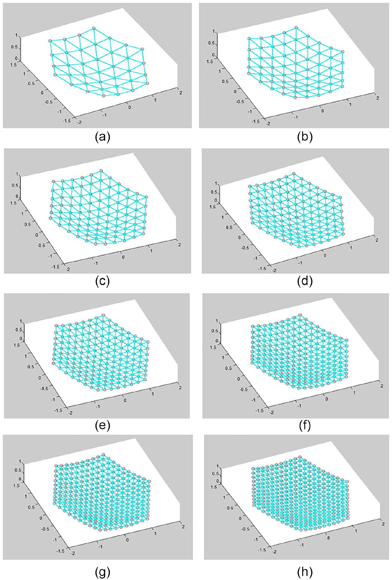
Triangle faceted mesh configuration with equal force density criteria. (a) N = 3. (b) N = 4. (c) N = 5. (d) N = 6. (e) N = 7. (f) N = 8. (g) N = 9. (h) N = 10.
Development of demonstration model
To verify the feasibility of the concept, a small scale prototype model of 1 m diameter is developed. In order to form a paraboloid shape, a nodal connector is used to connect horizontal and vertical tension ties. The nodal connector has a provision of a thread at the center to adjust the length of tension ties. From a single nodal connector, six horizontal cords and one vertical cord are passing. The small scale prototype model is shown in Figure 7.
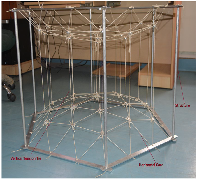
Demonstration model on scaled prototype.
The developed scaled model has been checked for numerous characteristics which make it particularly suitable for use on large deployable reflectors. The RF reflectivity in the S-band frequency for the developed model has been verified. The mesh should have a low coefficient of thermal expansion to handle the wide thermal variations as well as resistance to corrosion for the scaled model. The mesh of the scaled model has been tested for the wrinkle-free situation after being stowed for a longer period of time. Moreover, the condition of mesh that is, the formation of the crease of plastically deformation and maintaining surface integrity has been confirmed during repeated deployment and stowing cycle for the scaled model. The mesh of the large deployable reflector is made by single or multiple gold plated molybdenum or tungsten wires, as well as carbon fiber, reinforced silicon (CFRS) materials.
Theoretically calculated coordinates and measured coordinates of the prototype
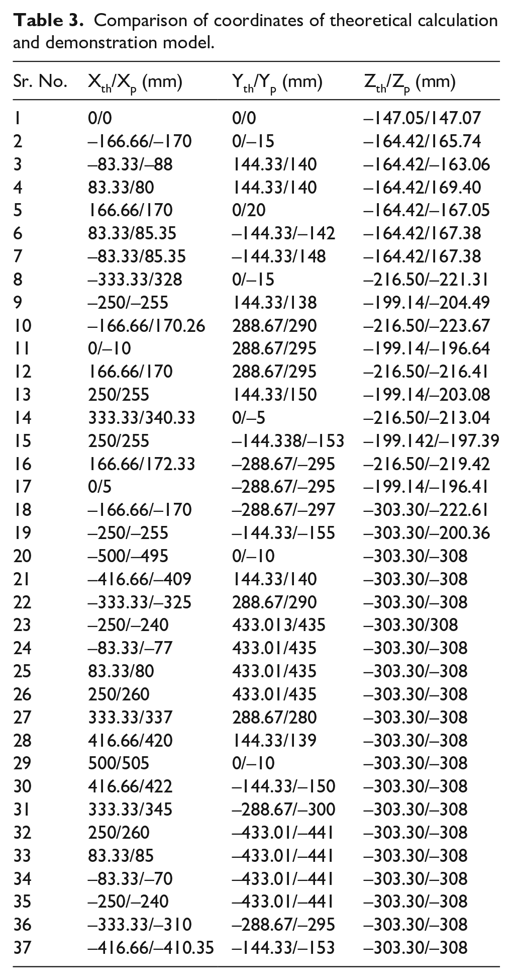
The coordinates of the front net and rear net along with tension ties are determined using force density and equal force density criteria for 1 m diameter scaled prototype using programming in MATLAB. The coordinates of the scaled prototype are measured with reference (origin) at the center of mesh configuration. The comparison of theoretically calculated coordinates with those of demonstration prototype is indicated in Table 3 wherein suffix “th” denoted theoretical prediction whereas suffix “p” denotes prototype. The difference between theoretically predicted data and actual measured data which is the root mean square errors are calculated for X, Y and Z directions. The RMS in the X direction is 7.36 mm, in the Y direction is 7.87 mm and in the Z direction is 4.29 mm.
Comparison of coordinates of theoretical calculation and demonstration model.
The provision for accommodate horizontal and vertical ties to achieve the paraboloid shape of the reflector surface has been kept in the scaled prototype model. The hexagonal structure of the scaled prototype has provision for mounting front cable net, rear cable net, and tension ties. In this scaled prototype all the outer nodes of the cable net are considered as fixed nodes.
Conclusion
By using the force density method the shape forming procedure implemented on the front net of the mesh reflector antenna for the proposed configuration. A methodology for the numbering of nodes and cables in mesh reflector is presented. Based on the force density and equal force density criteria a MATLAB code is generated for the different number of divisions of the aperture plane to find out the number of cables, the number of free nodes, maximum and minimum tension, mean length of cables, and faceting error. It is concluded that with the increase in the number of divisions gives a denser mesh and surface error varies from 3.97 mm to 0.36 mm as the number of triangular facets increases from 3 to 10. Higher surface accuracy can be achieved with increment in the number of triangular facets but it is not feasible to employ a too large number of triangular facets in the engineering application because it includes a complex manufacturing process. Force distribution is calculated using force density and equal force density method. The equal force density method gives a uniform distribution of force in each cable. The comparison of the coordinates of the prototype and those of theoretical calculation reveals that the results of the two methods are in close proximity.
Footnotes
Appendix
Declaration of conflicting interests
The author(s) declared no potential conflicts of interest with respect to the research, authorship, and/or publication of this article.
Funding
The author(s) disclosed receipt of the following financial support for the research, authorship, and/or publication of this article: The development of cable mesh deployable antenna reflector was carried out at Space Applications Centre, Indian Space Research Organization, Ahmedabad, India.