
Abstract
According to the architectural requirements, the roof structure of a large-span gymnasium adopts the suspen-dome structure. In the scheme selection stage of the pre-stressed cable-strut system at the bottom part of the suspen-dome structure, a Levy-type scheme and a Loop-free scheme are established. The finite element models are established, and the static analysis under the design loads, the whole process analysis of load-displacement, and the dynamic response analysis after accidental cable break are carried out. The architectural expression of the two schemes are discussed. The component material consumption, the structural stiffness, the tension distribution characteristics, and the static bearing capacity of the two schemes are discussed. The failure mode and the progressive collapse resistance of the two schemes after accidental cable break are also discussed. The results show that the Loop-free scheme requires significantly less in terms of component material consumption than the Levy-type scheme. The static failure mode of the two schemes is strength failure, but the Loop-free scheme has greater bearing capacity. The Loop-free scheme has greater structural stiffness, lower cable forces, and uniformly distributed cable forces in each layer, and lower stress on the top reticulated shell members. Neither of the two schemes experience progressive collapse after accidental cable break. Due to the rupture in the loop cable of the Levy-type scheme, the rigidity of the rear region decreases greatly, and the cable force loss is large. On the contrary, internal force redistribution occurs in the Loop-free cable scheme and the cable force loss is not obvious, hence the progressive collapse resistance is better than that of the Levy-type scheme.
Introduction
A gymnasium located in Zhejiang Province, China uses the suspen-dome structure. The architectural appearance of the gymnasium is shown in Figure 1. The gymnasium has 8000 seats, a construction area of about 22,600 m2, an elliptical plane projection, and the outermost outline size in the two main axis directions is 116 m × 109 m. The roof shape has a rise height of 9.5 m, and the roof plane projection diameter is 100.6 m.
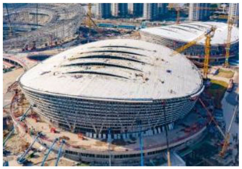
Aerial view of the gymnasium.
The substructure of the gymnasium is a reinforced concrete frame, and the roof structure adopts a suspen-dome structure. The suspen-dome structure is mainly composed of a top single-layer reticulated shell and the bottom is a pre-stressed cable-strut system. This design was first proposed by Professor Kawaguchi et al. 1 and has been applied to more than 20 long-span roofs.2–4
The pre-stressed cable-strut systems of existing suspen-dome structures mainly include the Geiger-type scheme 5 and the Levy-type scheme, 6 as shown in Figure 2. The Geiger-type scheme is in the shape of a wheel-spoke, composed of loop cables and radial cables. The form is simple and the construction difficulty is low. The Levy-type scheme is an improvement of the Geiger-type scheme. It is composed of loop cables and diagonal cables. Compared with the Geiger-type scheme, the stability of the Levy-type scheme is significantly improved and the construction difficulty is not changed much. Therefore, most of the suspen-dome structures built in recent years have adopted the Levy-type scheme.

Cable-strut systems in suspen-dome structures. (a) the Geiger-type, (b) the Levy-type.
Figure 2 shows that both the Geiger-type scheme and the Levy-type scheme use loop cables. In addition to having advantages, schemes with loop cables also have disadvantages including large tension in the loop cables and low redundancy. Scholars keep exploring new schemes for the suspen-dome structures while applying current schemes. Xue et al.7–9 developed a Loop-free scheme, as shown in Figure 3. In this scheme, the cables are straight on a plane projection, and slightly curved in the vertical direction. Hence, the space turning angle of every cable is small, and the force of the cable is directly transmitted to supports. The two ends of each cable are directly connected to the reticulated shell or the peripheral support bearings. Loop cables are not used in this scheme. Therefore, the cables are independent of each other, which helps prevent progressive collapse after an accidental cable break. Figure 3 shows that the cables in the same layer cross each other, and form a cable network, so that the integrity of the Loop-free scheme is good. Liu et al. 10 verified that the Loop-free suspen-dome structure had good static stability, and Li et al. 11 verified that the Loop-free suspen-dome structure had good progressive collapse resistance. The Loop-free scheme generally arranges vertical struts at the position where the cables cross. Liu et al. 10 paid attention to the problem of the dense arrangement of struts in the Loop-free scheme in some cases, and gave an optimal arrangement method for strut arrangement. Current studies have only demonstrated the feasibility of the Loop-free suspen-dome structure in terms of its mechanical properties and progressive collapse resistance. However, the advantages, disadvantages, and differences between the Loop-free scheme and the Levy-type scheme in terms of architectural expression, component material consumption, mechanical properties, and progressive collapse resistance are still unclear. It is necessary to conduct a comprehensive discussion about different schemes with the aim to provide a reference for determining the best pre-stressed cable-strut system for suspen-dome structures.
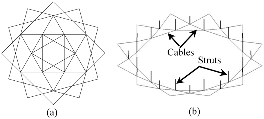
The Loop-free cable-strut system. (a) the plane projection, (b) the 3-D view of a layer.
In preliminary design stage of the gymnasium roof structure in Zhejiang Province, China, both the Loop-free scheme and the Levy-type scheme are tried for the suspen-dome structure, under the same reticulated shell. Architectural expression, component material consumption, structural stiffness, cable tension distribution, static bearing capacity, and progressive collapse resistance are compared and discussed.
Structural model information
Value of main loads
The weight of the structure members and connections is included. The roof system is 0.55 kN/m2, the equipment hanging is 0.25 kN/m2, and the gantry is 1.0 kN/m. Characteristic value of roof live load is 0.5 kN/m2. The basic snow pressure is 0.4 kN/m2 based on the recurrence period of 100 years, and the quasi-permanent value coefficient is divided into zone III. The GB 50011-2010 (2016 Edition) was used for seismic design. 12 The seismic fortification intensity is 6°, the basic design acceleration value is 0.05g, the design earthquake group is the first group, and the site category is IV. The temperature difference of the structure is ±25°C.
This project takes the envelope value of the equivalent wind load measured in the wind tunnel test and the wind load value calculated according to the GB 50009-2012 12 as the structural design wind load value. When calculating the wind load value according to the GB 50009-2012, the basic wind pressure is taken as 0.70 kN/m2 according to the recurrence period of 100 years, and the wind load carrier type coefficient is simplified calculation according to the closed arched roof in table 8.3.1 of the GB50009-2012. The vibration coefficient is taken as 2.0, and the wind pressure height variation coefficient is taken as 1.39 at a height of 30 m. According to the wind direction angle of the roof when the wind load is large provided by the wind tunnel test report, select the wind direction angles at 0°, 50°, 90°, 130°, 180°, 210°, 270°, and 340°. Overall, the wind load on the roof is dominated by wind suction, but when the wind direction angle is 130° and 180°, there is a non-negligible wind pressure on the roof.
Load combinations and roof deflection limit
According to GB 50068-2018, 13 GB 50009-2012 and GB 50011-2010 (2016 Edition), 14 in the static performance analysis of the structure, the serviceability limit state load combinations and the ultimate limit state load combinations are considered. Refer to the JGJ 257-2012, 15 the pre-stressed state of the cable after the tensioning construction is completed is taken as the initial state of displacement analysis. According to the JGJ 7-2010, 16 the roof deflection limit of this project under the combined action of dead loads and the roof live loads is taken as 1/400 of the span. The roof deflection limit under the effect of the roof live load alone is 1/500 of the span. The roof deflection limit under the most unfavorable conditions is 1/250 of the span. According to the GB 50011-2010 (2016 Edition), the deflection limit of the vertical seismic action is taken as 1/300 of the span.
Support conditions
The overall analysis model includes the suspen-dome structure, reinforced concrete ring beams, reinforced concrete columns, and V shaped columns, as shown in Figure 4. Reinforced concrete ring beams and reinforced concrete columns are the main supporting members of the suspen-dome structure. Steel friction pendulum bearings are set between the suspen-dome structure and the reinforced concrete ring beams. The bearings can slide along the radial direction but the other direction is fixed, the sliding distance is ±150 mm, which can effectively release the deformation of the roof under temperature change and cable pretension variation.

Overall analysis model.
The V shaped columns are the secondary supporting members of the roof structure. Due to the need for architectural shape, the top single-layer reticulated shell structure has a certain cantilever to the outside. There are 48 V shaped columns on the periphery to support the cantilevered part of the reticulated shell.
Component design
Except for the different cable-strut system schemes of the two suspen-dome structures, cross-sections, materials, and dimensions of members in other parts are the same. Reinforced concrete ring beams and columns are made of concrete C30, struts and V shaped columns are made of steel Q355B, and the stable stress ratio is limited within 0.85. The reinforced concrete ring beams adopt a rectangular solid cross-section, the concrete columns adopt a circular solid cross-section, and the struts and V shaped columns adopt circular pipes. When determining the cross-section form of the reticulated shell members, the requirements of the architect for the appearance of the members and connections are respected, and the large cross-sectional size of the reticulated shell members, the variety of types, and the difficulty of procurement are also considered. As a result, the box cross-section is adopted for the reticulated shell members. Figure 13 shows that the reticulated shell is a combination of a three-way pattern and a rib-ring pattern. The rib-ring pattern is the main pattern, and the small area in the center of the reticulated shell adopts the three-way pattern. In the rib-ring arrangement, the hoop members and the radial members of the reticulated shell are perpendicular to each other, hence, it is more feasible to use a box cross-section than other types.
Table 1 shows that there are seven kinds of box cross-section specifications of the reticulated shell members. The steel types used for different members are Q355B and Q390D, respectively. The total weight of the reticulated shell members including the cantilevered part is 767.6 t. The plane projection area of the top reticulated shell including the cantilevered part is about 9925 m2, and the steel consumption for the reticulated shell is about 77.34 kg/m2.
Cross-sections of the reticulated shell members.
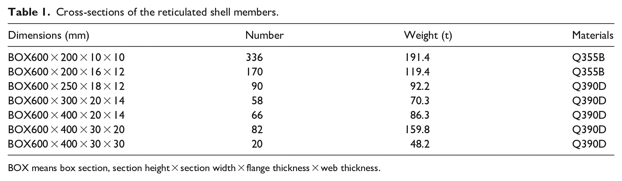
BOX means box section, section height × section width × flange thickness × web thickness.
Galfan-coated steel cables are used, the characteristic value of the ultimate tensile strength is 1670 N/mm2, and the elastic modulus is 1.6 × 10⁵ N/mm2. According to JGJ 257-2012, the partial coefficient of the cable should be 2.0, that is, the design value of the tensile strength of the cable is 835 N/mm2.
Cable-strut system schemes
Optimization method of cable-strut systems
The states of the suspen-dome structure in the process of design, production, construction, and service mainly includes the zero state, the pre-stressed state, and the load state. The deflection limit of the roof under the serviceability limit state load combination and the stress ratio limit of the ultimate limit state load combination is taken as the control condition for optimization. The minimum displacement of the reticulated shell under the pre-stressed state is taken as the optimization objective. Under the premise that the top reticulated shell structure is completely the same for the two schemes, finite element analysis is performed through ANSYS APDL language programming for form-finding analysis, and the optimal geometric dimensions, strut height, strut cross-section, cable cross-section, and cable pretension are obtained for the two schemes, respectively.
Layout of the Levy-type scheme
The layout of the optimized Levy-type scheme is shown in Figure 5. The number of cable loops of the built suspen-dome structures is generally 3–6 loops. Figure 5 shows that the number of cable loops in the Levy-type scheme in this project is four loops, and the dotted line represents loop cables. Figure 5 shows the spacing of the loops, the plane arrangement of the diagonal cables and the struts. The radius of the Levy-type scheme is 50.3 m, with 144 diagonal cables and 72 struts. The cross-sections, materials, and pretension of each loop cable, diagonal cable, and strut in the Levy-type scheme are listed in Table 2, where the negative sign indicates compression. The pretension of the loop cable in the first layer is the largest, and the pretension value of the loop cable in different layers decreases inward. The pretension of the diagonal cables and struts in the third layer are higher than those of the diagonal cables and struts in the second layer, mainly because the number of diagonal cables and struts in the third layer is only half of that of the second layer.

Layout of the Levy-type scheme.
Component information of the Levy-type scheme.

Layout of the Loop-free scheme
The optimized layout of the Loop-free scheme is shown in Figure 6. The number of layers of the Loop-free scheme in this project is three layers. In order to clearly show the spacing of the plane projections of each layer, a dotted line is drawn. The dotted line here represents the circumscribed circle of the polygon formed by the inner edge of each ring, which is not an actual component. The thick line, medium thick line, and thin line in Figure 6 represent the first layer cable, the second layer cable, and the third layer cable, respectively. The struts are arranged at the position where the cables cross. The first layer contains two loops of struts, and the second and third layer of cables contain only one loop of struts. The component information of the Loop-free scheme is listed in Table 3. The pretension of the cables and struts in each layer decrease inward.
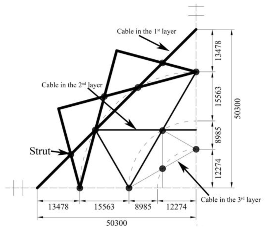
Layout of the Loop-free scheme.
Component information of the Loop-free scheme.

Results and discussion
Discussion on architectural expression
The architectural expression of the two schemes has their own characteristics, enriching the choices of architects. The Levy-type scheme is a traditional cable-strut system. The loop cables and diagonal cables are arranged in a regular manner. The appearance is sunflower-shaped, which demonstrates the concise and regular architectural expression that fits well with the rib-ring pattern of the top reticulated shell. The Loop-free scheme is a new-type cable-strut system. The cables are regularly cross-woven to show a cross shape similar to the roof structure of the Bird’s Nest Stadium in Beijing. It has strong artistic expression and demonstrates a novel and cross-rhythmic architectural expression.
Discussion on material consumption
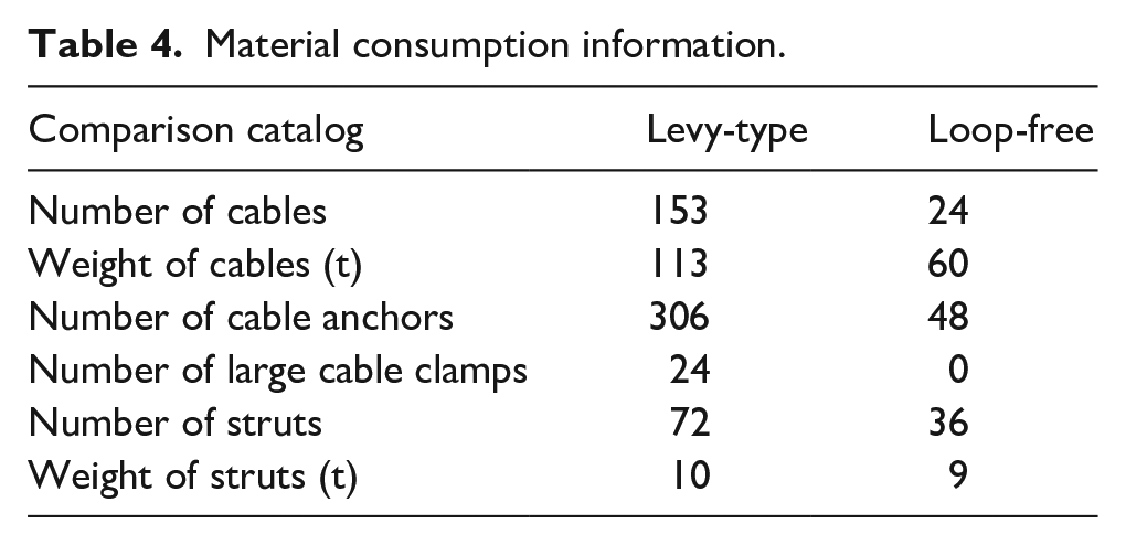
The consumption of cables, struts, and connections for the two schemes are shown in Table 4. The outermost loop cable of the Levy-type scheme is a cable bundle composed of three cables. The outermost loop cable has a circumference of about 258 m. Since the maximum length of the cable with a nominal diameter of 115 mm is about 100 m, the outermost loop cable must be spliced in two segments. The rest of the loop cables are less than 100 m in length, so there is no need to splice in segments. Integrating loop cables and diagonal cables, the Levy-type scheme requires a total of 153 cables. The Loop-free scheme has 24 cables. The total weight of the cables is calculated based on the cable length and section dimensions. The total weight of the cables is 113 t for the Levy-type scheme and 60 t for the Loop-free scheme. The Levy-type scheme requires 24 large cable clamps for connecting the diagonal cables and the loop cable in the outermost layer, while the Loop-free scheme does not require a large cable clamp. Each cable requires two anchors. According to the number of cables, the Levy-type scheme requires 306 cable anchors, and the Loop-free scheme requires 48 sets of anchors. In terms of struts, the number of struts in the Loop-free scheme is more than that in the Levy-type scheme, but the weight of struts of the Loop-free scheme is less. In short, the number of cables, weight of cables, number of cable anchors, and weight of struts required for the Loop-free scheme are less than those of the Levy-type scheme. Especially noteworthy, the Loop-free scheme does not require large cable clamps which are usually expensive. Therefore, the Loop-free scheme has advantages in terms of component material consumption.
Material consumption information.
Discussion on the stress of reticulated shell
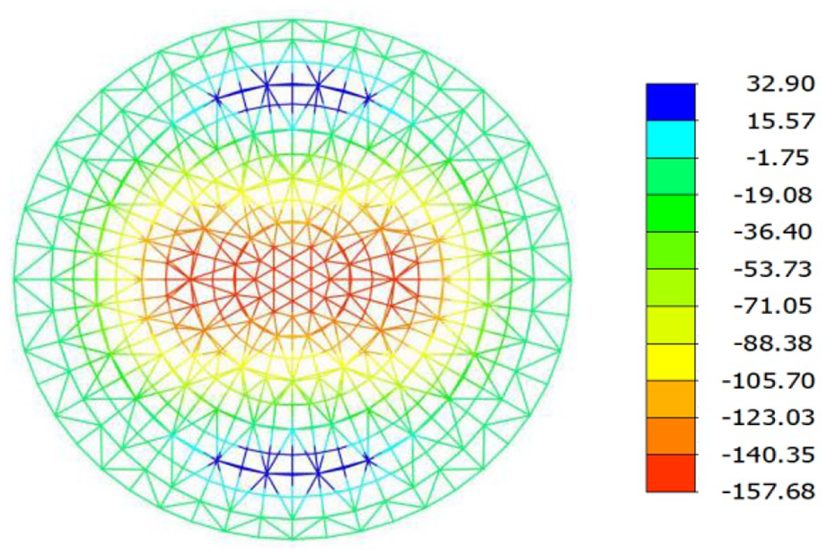
Figures 7 and 8 show the resultant stresses of the top reticulated shell members of the Levy-type scheme and the Loop-free scheme in a pre-stressed state, respectively. The maximum tensile stress and the maximum compressive stress of the shell members of the Levy-type scheme are 132 and −168 MPa, respectively. The maximum tensile stress and the maximum compressive stress of the shell members of the Loop-free scheme are 81 and −72 MPa, respectively. In short, in a pre-stressed state, the stress of the shell members of the Loop-free scheme is smaller.

The envelope resultant stresses of the Levy-type scheme in pre-stressed state (MPa).

The envelope resultant stresses of the Loop-free scheme in pre-stressed state (MPa).
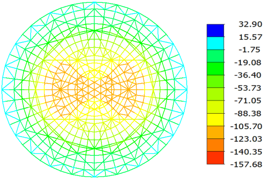
Under the action of the ultimate limit state load combinations, the envelope resultant stresses of the shell members of the Levy-type scheme and the Loop-free scheme are shown in Figures 9 and 10, respectively. The maximum tensile stress and maximum compressive stress of the shell members of the Levy-type scheme are 127 and −264 MPa, respectively. The maximum tensile stress and the maximum compressive stress of the shell members of the Loop-free scheme are 108 and −189 MPa, respectively. In a word, under the action of the ultimate limit state load combinations the stress of the reticulated shell members of the Loop-free scheme is smaller.
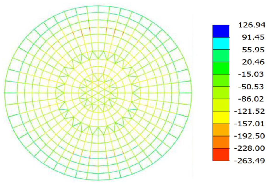
The envelope resultant stresses of the Levy-type scheme in loaded state (MPa).

The envelope resultant stresses of the Loop-free scheme in loaded state (MPa).
Discussion on structural stiffness
Under the action of the serviceability limit state load combinations, the envelope vertical displacements of the two schemes are shown in Figures 11 and 12, respectively. Figure 11 shows that the maximum envelope vertical downward displacement of the Levy-type scheme is −157 mm, which is located in the center of the roof.
Envelope vertical downward displacements of the Levy-type scheme (mm).
Envelope vertical downward displacements of the Loop-free scheme (mm).
Figure 12 shows that of the Loop-free scheme is −120 mm, which appears in the center of the roof. In short, under the same load combinations, the deflection of the Loop-free scheme is smaller, which indicates that a structure using the Loop-free scheme is more rigid. The reason is that the plane projection of the cables in the Loop-free scheme are straight lines, so that the force transmission is direct, the cables cross each other, hence the integrity is better, improving the support effect of the cable system.
Discussion on cable tensions
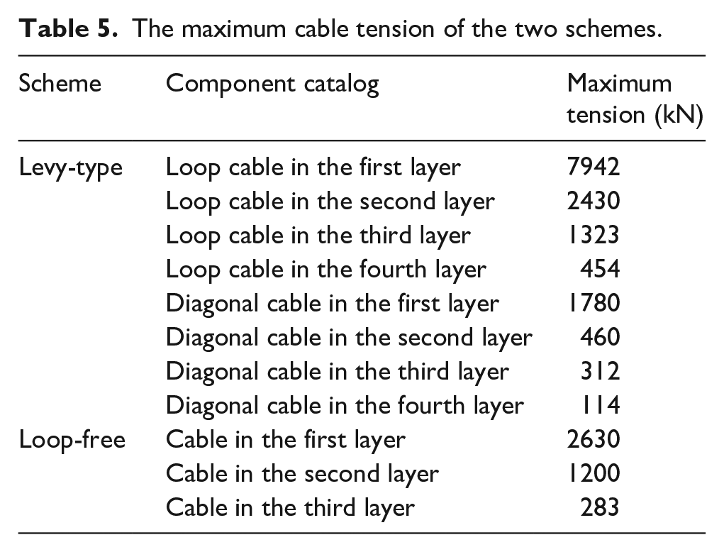
Under the action of the ultimate limit state load combinations, envelope values of cable tensions of the two schemes are shown in Figures 13 and 14, respectively. Both the Levy-type scheme and the Loop-free scheme show a decreasing trend of cable tensions inwards. The maximum cable tension of the two schemes is listed in Table 5. The ratio of the loop cable tension to the diagonal cable tension in each layer of the Levy-type scheme exceeds 4.0. It indicates that the cable tension distribution of the Levy-type scheme is not uniform. This is determined by the angle between the cables. The angle between adjacent cable segments of the loop cable is obtuse and close to a flat angle, while the angle between the diagonal cables is an acute angle. As a result, the loop cable needs a greater tension to balance tension in the diagonal cables. Figure 14 shows that envelope cable tension of the outermost layer of the Loop-free scheme is between 2420 and 2640 kN, the second layer is between 990 and 1200 kN, and the innermost layer is between 243 and 282 kN. The ratio of the maximum cable tension to the minimum cable tension in each layer of the Loop-free scheme is less than 1.2. It indicates that the cable tension is uniformly distributed in the Loop-free scheme. The maximum cable tension of the Levy-type scheme is 7942 kN, while that of the Loop-free scheme is 2630 kN. In short, under the same load the Loop-free scheme has less cable tension and more uniform distribution of cable tension than the Levy-type scheme.
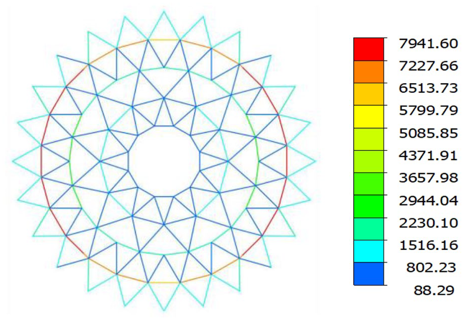
The envelope cable tensions of the Levy-type scheme (kN).
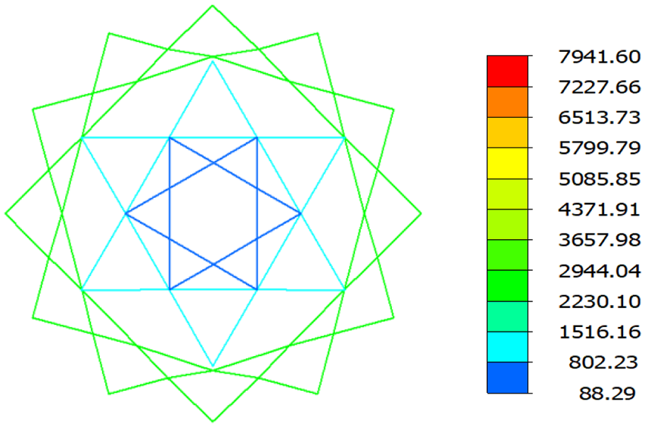
The envelope cable tensions of the Loop-free scheme (kN).
The maximum cable tension of the two schemes.
Static bearing capacity and failure mode
Stability analysis is an important part of the structural design of the suspen-dome structure. The arc length method is used to analyze the stability. Taking the standard load combination as the reference load value, the load-displacement process curve is obtained as shown in Figure 15. The JGJ 7-2010 recommends that the load value corresponding to the first drop of the load-displacement curve is taken as the structural bearing capacity, and the ratio of the bearing capacity to the standard load combination is used as the safety factor. The safety factors of the Levy-type scheme and the Loop-free scheme are 3.16 and 3.41, respectively. The Loop-free scheme is 8% higher than the Levy-type scheme. In addition, the load-displacement curve of the two schemes does not drop significantly after reaching the highest point, but continues to deform while maintaining high bearing capacity, showing the strength failure mode.

The load-displacement curve of the two schemes.
Progressive collapse resistance
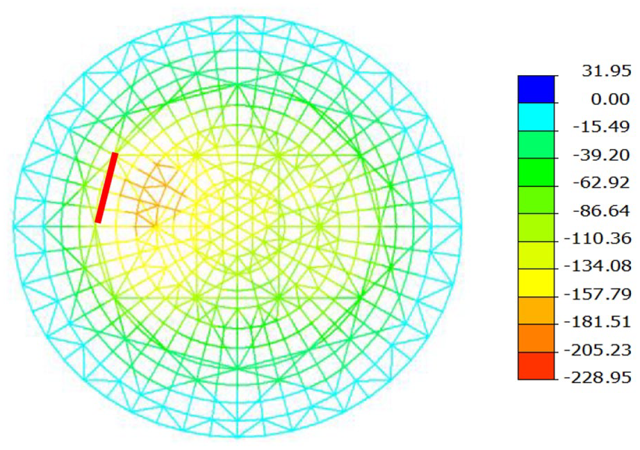
Due to the low redundancy in the pre-stressed cable-strut system, the suspen-dome structure is sensitive to cable failure. It is necessary to analyze the progressive collapse resistance after an accidental cable break. The displacements and cable tensions after the cable is broken are shown in Figures 16 to 19. The results show that the two schemes do not collapse after breaking one of the most unfavorable cables, and both meet the requirements of progressive collapse resistance.

The envelope vertical displacements of the Levy-type scheme after accidental cable break (mm).
The envelope vertical displacements of the Loop-free scheme after accidental cable break (mm).
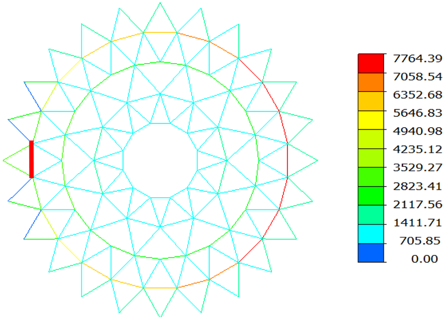
The envelope cable tensions of the Levy-type scheme after accidental cable break (kN).

The envelope cable tensions of the Loop-free scheme after accidental cable break (kN).
Figure 16 shows that after the cable is broken, the maximum vertical displacement of the Levy-type scheme under the serviceability limit state load combinations is −229 mm, which is an increase of 72 mm compared to that before the cable is broken. Figure 17 shows that the maximum vertical displacement of the Loop-free scheme is −172 mm, which is an increase of 50 mm compared to that before the cable is broken. It shows that the degree of structural stiffness degradation of the Loop-free scheme is smaller. This phenomenon can be explained by the change of the cable tensions after the cable is broken. Figure 18 shows that the cables lose tension significantly in the Levy-type scheme, while Figure 19 shows that only the cables on the same line with the broken cable lose tension. The tension of the remaining cables is almost unchanged. In the Loop-free scheme, the cables are relatively independent, and the rest of the cables remain stressed after a cable segment breaks. The cables are crossed and woven into a whole. After the cables are partially broken, the cables that intersect with them serve as backup load transfer paths and prevent the spread of initial damage. In short, the Loop-free scheme is more robust and has good resistance to progressive collapse after an accidental cable break.
Conclusion
The artistic design of the two schemes have their own characteristics, enriching the choices of architects. The Levy-type scheme is a traditional cable-strut system. The loop cables and diagonal cables are arranged in a regular manner. The Loop-free scheme is a new-type cable-strut system. It has strong artistic expression and demonstrates a novel and cross-rhythmic architectural expression.
In terms of material consumption, the Loop-free scheme has more advantages. The number of cables, the weight of the cables, the number of cable anchors, and the weight of the struts required by the Loop-free scheme are significantly less than those of the Levy-type scheme. The Loop-free scheme also does not require large cable clamps.
The Loop-free scheme obtains greater structural stiffness, larger bearing capacity, and better progressive collapse resistance. Cable tensions of the Loop-free scheme are smaller than that of the Levy-type scheme. Cable tensions of the Loop-free scheme also are more uniformly distributed in each layer.
Footnotes
Declaration of conflicting interests
The author(s) declared no potential conflicts of interest with respect to the research, authorship, and/or publication of this article.
Funding
The authors disclosed receipt of the following financial support for the research, authorship, and/or publication of this article: This study was funded by the Natural Science Foundation of Shandong (ZR201911030049).