
Abstract
This paper provides a review of early development studies on structures carried out by NASA and US aerospace contractors between 1975 and 1985 before and during the initiation of the Space Station programme. The studies envisioned very large structures built in orbit using the Space Shuttle, then in the process of entering service. Their original purpose was to function as solar power, antenna and communications platforms. The studies explored the application of automatically-fabricated trusses, then preassembled deployable trusses, and then astronaut-assembled erectable trusses. By the time of the Station’s go-ahead in 1984, a large erectable truss structure formed the backbone of the Station’s design. Erectable trusses were successfully tested on a Space Shuttle mission in 1985 but later abandoned after the Shuttle Challenger disaster in 1986. Taken together, the 1975–1985 development studies have much historical significance as the first generation of ideas about large engineered structures for extraterrestrial applications.
The United States began work on the development of the Space Shuttle in 1968 as the Apollo programme approached operational status with the first landing on the Moon just a year away. 1 By 1971, the basic design of the Shuttle system had emerged with a vertically-launched, winged spaceplane mounted on a large liquid fuel tank flanked by solid booster rockets. The spaceplane would have a bus-sized cargo bay capable of delivering a wide range of payloads to orbit for both civilian and military purposes. President Richard Nixon approved the project in 1972. 2 The decision to develop what would be a space delivery truck opened up the prospect of building major structures in space.
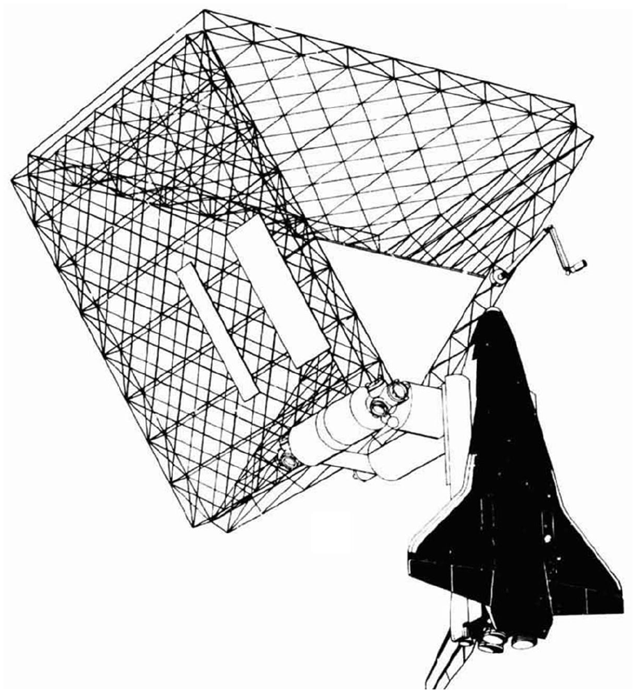
From the late-1960s, long before a station emerged as the leading project for the US human spaceflight programme, NASA and its aerospace contractors were already exploring the feasibility of building very large structures in orbit, such as solar power generation and communications platforms. The structures were to be very lightweight with overall dimensions in the hundreds of metres. From the mid-1970s onwards, these studies began to focus on the forthcoming Space Shuttle as the delivery vehicle. Figure 1 shows an illustration of a typical concept taken from a contractor report at the time. 3 A series of triangular prism trusses projected out to port and starboard of the Shuttle. Manufacturing of the trusses would occur in space supported by central machinery rotated out at right-angles from the payload bay.

Concept for a large space structure, 1978.
During these years, three types of structure emerged as candidates for delivery to orbit in the Shuttle’s payload bay. First were manufactured structures produced automatically by purpose-designed machines that used raw material stock and forming tools integrated into the machine itself. Second were deployed structures that unfolded and extended from hinged and jointed frames stowed in stacks for launch. Third were erected structures assembled by astronauts or machines from individual struts and nodes packed in batches for launch. Two contractors that carried out parallel studies for manufactured structures at the time were Grumman Aerospace Corporation and General Dynamics. ‘Beam builder’ was the name given to the machines that would manufacture the structures. In 1978, Grumman built a fully operational prototype of a beam builder that produced aluminium trusses, 4 shown in Figure 2. General Dynamics developed a design for a beam builder producing composite trusses that did not reach prototype stage. Grumman’s beam builder was of ingenious design and ranks as the first large manufacturing tool designed to work in space. It produced a triangular prism truss made of aluminium with a 1 m side diameter and 1.5 m bay length. In Figure 2, the enclosing framework (white) was a substantial structure designed to withstand the Shuttle’s launch loads of 3 g. The machine formed the three longerons using a sequence of seven rolling mill stations with each mill progressively bending the open-triangle longeron shape from 162 mm × 0.4 mm flat stock wound into reels. Each reel held 300 m of flat stock and was replaceable. Stored in magazines (yellow) were preformed vertical and diagonal bracing struts made of the same stock. The machine fed these at precise intervals onto the longerons according to the truss’s bay pattern. A carriage mechanism placed each strut against a longeron at each fastening position where a block clamped it and spot-welded it at six points at each end. Meanwhile the carriage mechanism retracted to prepare for the next cycle. Attached first were the vertical struts, followed by the diagonal struts. Each magazine contained 200 bracing struts which were enough to produce a 300 m long truss. Three guillotines trimmed each longeron to the desired length. 5 Controlling the beam builder was a computer and workstation that monitored all the manufacturing functions, cycle by cycle. The beam builder prototype produced several trusses of this type. Successfully tested was a 40 m long truss of 26 bays under a combined bending and axial load that passed the ultimate design load of 571 kg.

Prototype of an automated beam builder, 1978.
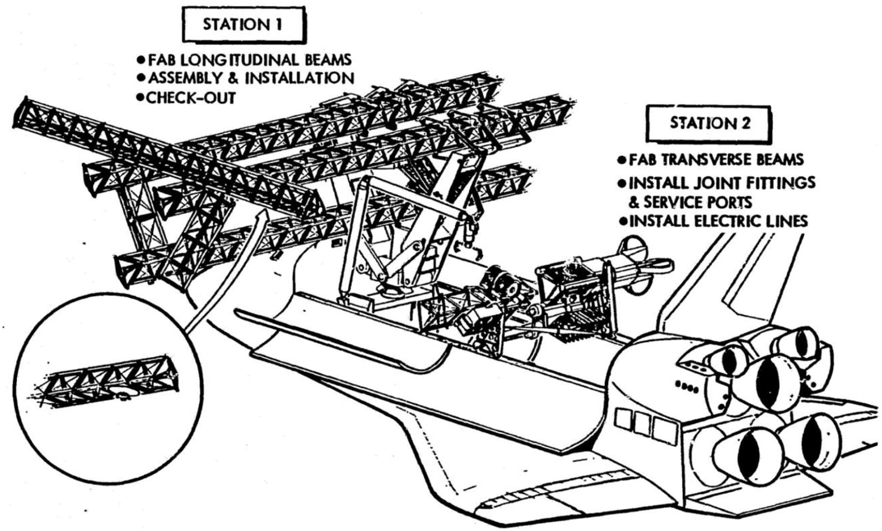
NASA’s review of the beam builder tests was favourable, anticipating that it could be used to build a wide range of very large structures. 6 The list covered reflector antennas, microwave radiometer antennas, radar astronomy telescopes, solar thermal power systems, photovoltaic solar power systems, microwave power transmission antennas, communications systems and crewed space stations. This was an early instance where NASA had mentioned a space station in the context of active hardware development. Parallel to beam builder development was an analysis for NASA by Rockwell International that evaluated the activities, techniques, equipment and Shuttle provisions required to construct a large candidate structure in orbit based on beam builder construction. 7 The structure was to function as a platform for testing a 4000 sq.m solar power array as well as multi-beam communications antenna technologies. Rockwell concluded that it was possible to build such structures using automation but there were major challenges. Advanced robotic arm and spacesuit technologies would be essential and uncertainties in the construction process, such as the installation of electrical systems and accessories, should be tested in flight experiments. Figure 3 shows an illustration of the candidate structure. The manufactured trusses functioned as three longitudinal beams arranged to form a scaled-up, open-sided triangular prism around 100 m long. Connecting the beams at right-angles were braces on their upper sides and booms on the underside that extended out to port and starboard, all fabricated from the same truss material. At one end were propulsion modules and at the other a solar power array. Figure 4 shows the proposed method of construction in orbit from the Shuttle’s open payload bay. Raised out of the centre of the bay to starboard was the beam builder, shown manufacturing a piece of truss that rolled out to port. Forward of this was a sill-height platform supporting a hinged crane that held the assembled structure and a robotic arm that manipulated completed trusses into position.
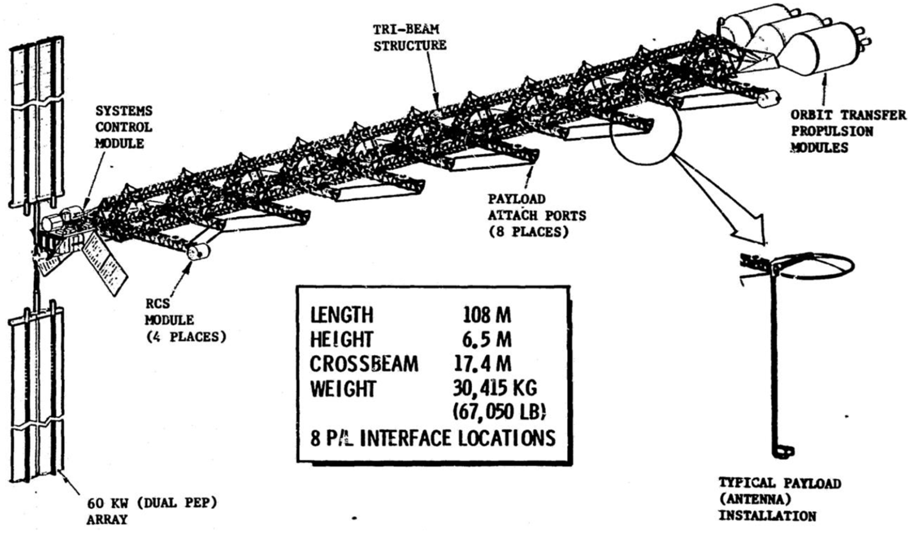
Large candidate structure for prospective beam builder construction, 1980.
Using the shuttle as an automated construction platform, 1980.
In early 1980, NASA awarded parallel studies to Boeing and McDonnell Douglas to develop competing designs for a permanently-occupied orbital facility. McDonnell Douglas avoided the use of large structure in a design called an Evolutionary Space Platform. Boeing featured it in a design called a Space Operations Centre, shown in Figures 5 and 6. Boeing utilised large structures as part of a complex design that functioned as an orbital assembly site for crewed and automatic spacecraft, a construction and check-out facility for large orbital platforms, a satellite servicing and repair garage, and a permanently-occupied base. NASA did not call it a space station and it did not yet include any research capabilities. It was an operations centre, not a scientific one. In the left foreground in Figure 5 was a construction platform with a beam builder manufacturing a series of trusses. The platform was berthed to the end of a service tunnel that acted as a spine and supported two pressurised habitation modules, a pressurised robotic operations module and an external assembly framework. Projecting out to port and starboard were solar arrays and radiator panels mounted on long booms. 8 Figure 6 shows an evolved version of the same design. The module configuration to the right was broadly the same as before, but the beam builder, finished producing trusses, was now parked on the near end of the construction platform.

Concept for a space operations centre, 1980.

Concept for a space operations centre, 1981.
12 April 1981 saw the inaugural flight of the Space Shuttle when NASA launched the Orbiter Columbia into orbit. 9 The Space Shuttle era had begun and design work on a space station now gathered pace. NASA appointed a space station task force that awarded eight contracts in 1982 to US aerospace companies to pursue designs based on sets of criteria that they would draw up themselves. NASA’s study title was the Space Station Needs, Attributes and Architectural Options Study. 10 Covered were mission requirements, design configurations, mission operations, market research, benefits to society and cost-value analyses. Contracts went to Boeing, Rockwell, Lockheed, McDonnell Douglas, General Dynamics, Martin Marietta, TRW and Hughes Aircraft. In the final designs, large structure was mostly absent and what structure there was generally had a secondary role. The focus was on clusters of pressurised modules linked in different configurations. There were laboratory modules for physical sciences, life sciences and materials processing and day and night habitation modules for the crews. 11 Driving the new shift towards scientific research as a priority were the market surveys that the contractors had carried out as one of their tasks. Figure 7 shows two examples of designs from General Dynamics and Martin Marietta. General Dynamics featured a length of large-bay truss supporting two cylindrical hangars and a propellant storage module. Martin Marietta featured two slender trusses projecting out like booms that supported pallets at one end and materials modules at the other. Work on large structures continued. In 1982, Rockwell again and Vought Corporation carried out parallel studies in which the emphasis had moved away from structures fabricated in orbit by a beam builder to self-deploying structures with hinged joints that folded into compact stacks for launch, complete with integrated utility systems, and then expanded to their final shape once in orbit. NASA had added a study requirement for deployable volumes that referred to space hangars for spacecraft known as orbital transfer vehicles and modules for a space station, by then beginning to emerge as a major project. NASA still anticipated that the structures would fulfil an emerging need for space platforms that would perform various functions. By now, NASA had decided to proceed with deployable structures because of the difficulties of joining machine-made structures and installing utility systems and accessories in space. 12 There were too many unknowns and uncertainties with the beam builder approach and the amount of extra effort needed to complete the structures. Rockwell and Vought focussed on systems of struts and hinged joints that formed into rectangular box trusses and triangular prism trusses. The structures arrived in orbit as folded stacks, rather like packs of interconnected playing cards, stowed inside cage frameworks that restrained them during launch and helped to control their automatic deployment.
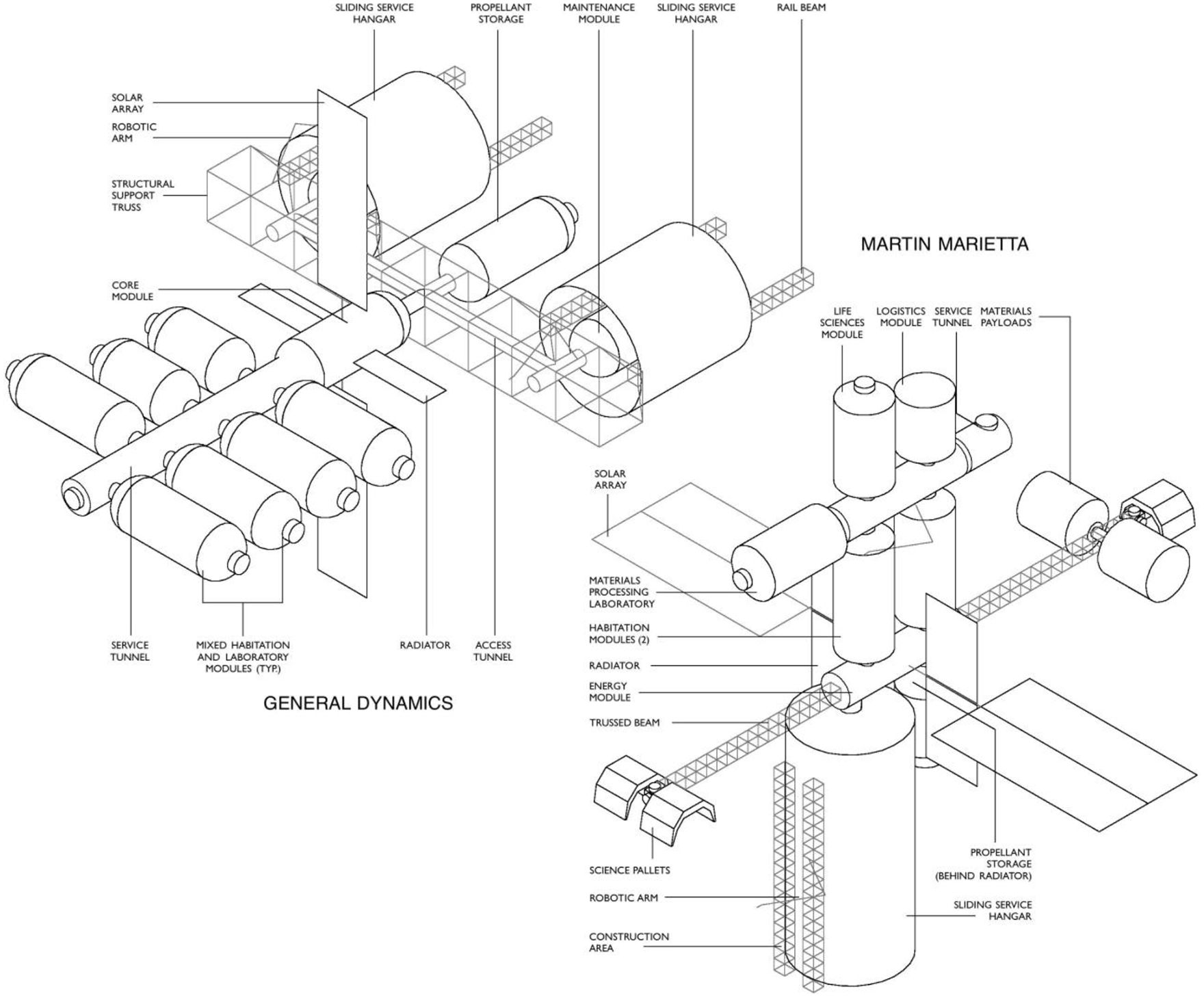
Two examples of approaches to the space station design, 1982.
Figure 8 shows an illustration of one of Rockwell concepts. The four longerons were round tubes hinged at their mid-points enabling them to stow flat within the thickness of the quasi-bulkhead frames of four rigid struts. The truss had a side dimension of 1.4 m. The diagonals were telescopic tubes. The stacked structure unfolded from its cage guided by tracks that supported each bay while its struts unfolded and its joints locked, after which it could cantilever outwards in weightlessness. Added later was a sophisticated and complex mechanical deployment and retraction methodology. 13 The proposed material was graphite composite. Vought examined trusses with different folding methodologies and selected a double-fold truss that expanded on two axes during the unfolding sequence as a candidate for a ground test. 14 The biaxial double-fold truss had a side dimension of 3 m. Figure 9 shows a ground-test scale model of Vought’s design partially deployed (left) and fully deployed (right). The first unfold in the longitudinal direction was an accordion type with top and bottom hinged joints connecting the longerons as they pushed outwards to form straight lines. Synchronised with the first unfold was the second unfold that extended the perpendicular and diagonal bracing struts on hinged joints to form the truss sides. The double-fold method was feasible for both single trusses and multi-truss platforms.

Deployment methodology for a rectangular box truss, 1982.
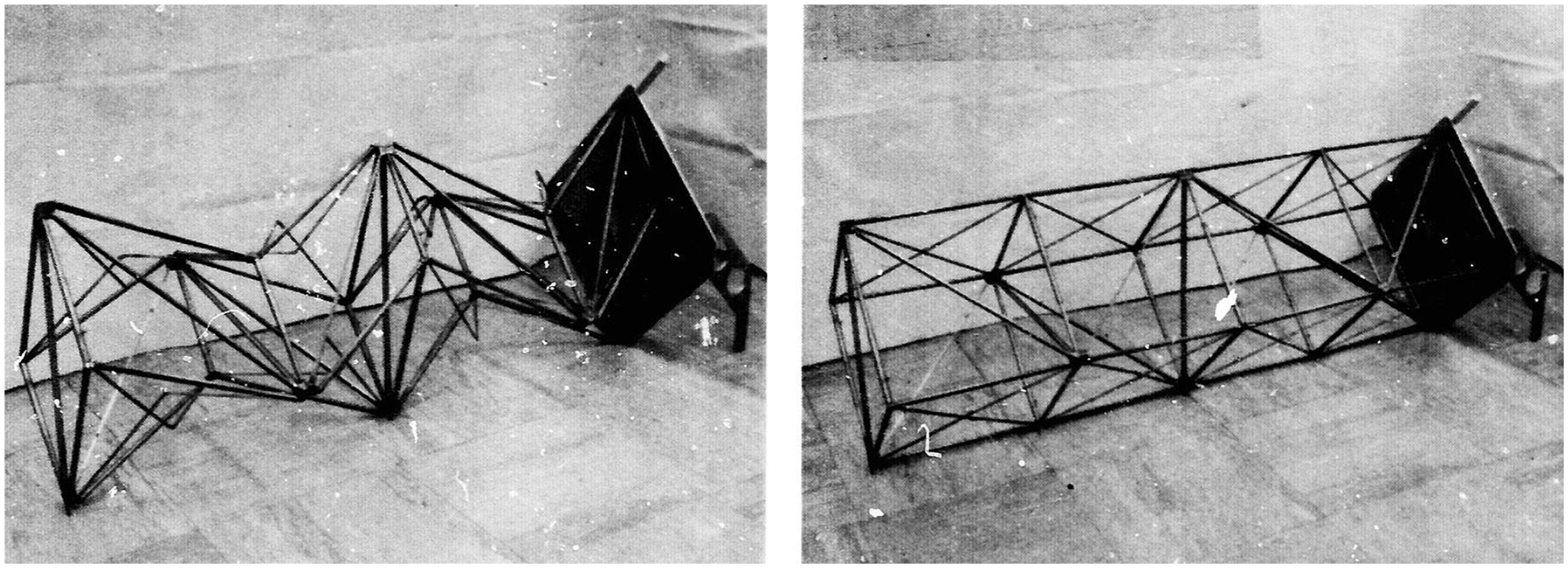
Prototype of a deployable double-fold box truss, 1982.
Both the Rockwell and Vought designs were clever solutions to the challenge of building structures in orbit but they had deficiencies and posed risks. Though debris and meteoroid protection was of supreme importance to the integrity of pressurised crew modules as they recognised, it was also important to the integrity of structural frames. A major fracture of a longeron by a piece of space debris impacting at a relative velocity of several kilometres a second may not necessarily lead to catastrophic failure of a four-longeron truss in weightlessness but it would reduce the truss’s strength, stiffness and ability to function properly before it was repaired. Severely weakened would be compression, bending and torsion resistance. If the truss was performing a vital role, such as providing power from solar arrays to a cluster of pressurised modules, a failure of any sort would pose an unacceptable danger to the crew. Then there was the potential difficulty that spacesuited astronauts would experience in accessing and repairing these intricate structures with their hinged joints. At this point, NASA had no test experience of any kind in building or repairing structures in space. There was no mention of risks to and repairs of the truss structures. If a deployable structure was to feature as a major element of the forthcoming space station, flight testing of prototypes by astronauts on a Shuttle mission would be an essential step.
Towards the end of 1983, NASA itself carried out a study of potential space station designs. Entitled the Conceptual Design and Evaluation of Selected Space Station Concepts, 15 the study, led by Johnson Space Centre working for NASA headquarters, had a vision that was far more ambitious than the recent studies by the contractors. NASA called it a special emphasis study to define new concepts to meet new requirements. It resulted in three distinct structures of which two – entitled the ‘Delta’ and the ‘Big-T’ – were monumental-scale designs. The third design was an evolved version of the earlier Space Operations Centre. Figure 10 shows the Delta design. It comprised a very large triangular prism with three sides made from deployable structures. The prism’s interior was hollow and intended as a giant spacecraft hangar. Mounted along its bottom edge was a cluster of pressurised modules. Solar arrays covered one side and utilities, experiments and payloads covered the other two. NASA went as far as patenting the Delta design. 16 Figure 11 shows the Big-T design. A vertical deployable structure formed the plane of the T’s mast. Attached to the top of this was another deployable structure that formed the plane of the T’s crossbar. Attached at the base was a module cluster, hangars and a work platform. Mounted on top of the crossbar were solar arrays, antennas and astronomy instruments. NASA estimated that just six or seven Space Shuttle missions would be able to launch the initial version of either design. Drawings showed that this included one long module, four short modules, a connecting tunnel, a hangar and other equipment. These elements would need at least four flights, leaving at the most three flights for the structure. For the Delta design, three flights equated to the delivery of one whole prism side on each flight. This was optimistic given the scale and complexity of the structures involved.
The ‘Delta’ Space Station Concept, 1982.

The ‘Big-T’ Space Station Concept, 1982.
President Ronald Reagan gave the go-ahead to a Space Station, as it was now officially named, in January 1984. 17 Directing the project was the Space Station Programme Office at NASA headquarters in Washington D.C. It was now urgent to produce a single feasible design for the Space Station out of all the concepts studied since the 1970s. NASA had selected five candidates for final evaluation: the Delta, the Big-T, a ‘Planar’ design distilled from the eight projects in the 1982 Space Station Needs, Attributes and Architectural Options Study, a rotating ‘Spinner’ station that had been Hughes Aircraft Company’s 1982 entry, and a new design called the ‘Power Tower’. It was the Power Tower that NASA chose and unveiled in August 1984. 18
Figure 12 shows the Power Tower’s design. It resembled a giant cross. Assembled from rectangular box trusses were a 121 m high vertical mast and a 80.5 m wide horizontal crossbar. Each side of the crossbar supported solar arrays and radiators. At the top of the mast pointing out into space was a short crossbar supporting astronomy and astrophysics instruments and antennas. Mounted on the sides of the mast were hangars and satellite bays. At the base of the mast pointing down to Earth were the habitation, laboratory and logistics modules. NASA, in another optimistic assessment, thought that the Shuttle could deliver all the Power Tower’s building blocks to orbit in just seven missions. Evaluated were three different designs for the mast and crossbar structures: first, deployable single-fold trusses; second, deployable double-fold trusses; third, erectable trusses. Each had advantages and disadvantages. The erectable truss with a 4.6 m side dimension had the fewest component parts, the lowest mass and greatest stiffness but would need a lot of astronaut assembly time in space. By contrast, the 2.7 m deployable single-fold truss would require minimum astronaut attention in orbit and ground assembly could be verified before launch, but NASA still had no space experience of any kind with deployable structures. 19

The ‘Power Tower’ Space Station Reference Design, 1984.
The Power Tower design, however, had a serious design fault that emerged a few months later, rendering it useless for scientific research. The fault lay in locating the laboratory modules at the base of the mast where they would experience both a gravity gradient and induced vibrations. A gravity gradient is a small but quantifiable variation in a gravitational force as one moves away from the centre of mass of a spacecraft. The centre of mass of the Power Tower was close to the crossbar and high above the laboratory modules. They would experience a slight gravitational force as a result as well as structural vibrations from crew movement in the modules that the mast structure would tend to amplify. 20 The Station’s declared purpose was to carry out scientific research in as near a perfect weightless environment as was possible. Disturbances to that weightlessness, however slight, were unacceptable to the scientists. NASA had failed to consult the scientific community before producing the Power Tower design and scrapped it, and by mid-1985 had replaced it with a revised design named the ‘Dual Keel’ shown in Figure 13. 21 Gone was the tall mast, replaced by a rectangular trussed frame resembling a giant keel with the long sides vertical and the crossbar passing through its midpoint. The laboratory modules were now close to the centre of mass.

The ‘Dual Keel’ Space Station Design, 1985.
With a new Station design, the time had arrived to make a decision on the type of truss to be used for the Station’s structure. A new analysis examined four truss structure options. 22 They comprised a 2.7 m deployable single-fold truss, a 3 m deployable double-fold truss, a 5 m erectable truss, and a new design called a Pactruss. NASA concluded that the 5 m erectable truss offered the most potential. It would enable growth simply by adding more struts and nodes, it had plenty of capacity for attaching payloads. It was lower in mass with a lower number of component parts than the other trusses. Most importantly, another new analysis showed that with one longeron damaged or missing, the 5 m truss would retain adequate structural stiffness and load carrying capability. 23 Erectable structures would now be tested in space. In November 1985, Space Shuttle mission STS-61B launched to orbit carrying two full-scale structures experiments called ACCESS and EASE that the crew would test-assemble in the open payload bay. Figures 14 and 15 respectively show the EASE and ACCESS experiments in orbit. ACCESS stood for Assembly Concept for Construction of Erectable Space Structures and EASE for Experimental Assembly of Structures in Extravehicular Activity. The two experiments proved to be highly successful. They gave astronauts hands-on experience of assembling structures in space for the first time, indicated where improvements could be made to the design and performance of erectable structures, and enabled comparisons with test assembly procedures on the ground. 24 Two astronauts assembled the structures by snapping the components together without tools and they then took them apart. The tests indicated that the larger EASE structure would be the best solution for the Space Station. Indicating a need for caution, however, an extrapolation of the work effort and time taken from the tests suggested that it would take seven Shuttle missions and 116 astronaut hours just to build the Station’s 5 m truss structure as then designed. 25 Confirming the reasons for the final choice of the 5 m rectangular box structure, NASA summarised its advantages as greater stiffness, lower mass, lower number of components, lower cost, better growth potential and more payload accommodation. 26
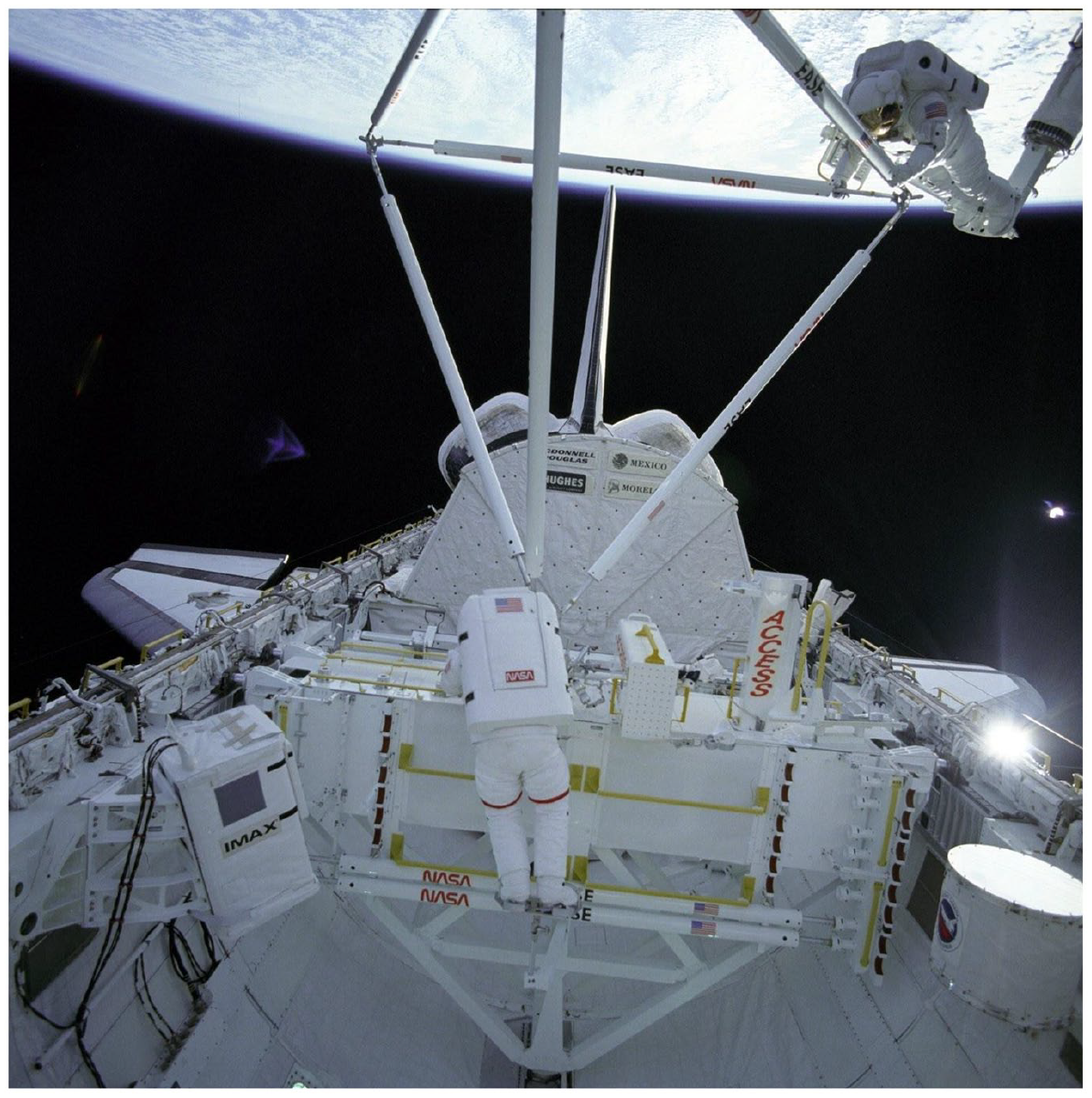
The ‘Ease’ Space structure experiment on STS-61B, 1985.

The ‘Access’ Space structure experiment on STS-61B, 1985.
On the morning of 28 January 1986, Space Shuttle mission 51-L exploded after launch with the loss of the crew on board the Orbiter Challenger. That disaster, fully chronicled by the commission that investigated its causes, 27 had a profound impact on the course of the Space Station’s subsequent design and development. It resulted in the abandonment of the 5 m erectable truss structure and its replacement with a rigid structural frame fully prefabricated on the ground and lofted into orbit, piece by piece. Discussion of this later structure that today forms a major part of what is now the International Space Station 28 is beyond the scope of this paper which has focussed on structures development work between 1975 and 1985.
Conclusion
The large orbiting structures reviewed in this paper emerged during a decade of design and engineering studies that began in the mid-1970s with the introduction of the Space Shuttle as a transportation vehicle and ended in the mid-1980s with the finalisation of the Space Station’s truss design. The designs were inventive and innovative solutions to the problem of delivering ambitious structures to orbit in a physically efficient and economical manner. Taken together, they have much historical significance as the first generation of ideas about large engineered structures for extraterrestrial applications. The International Space Station’s lifespan has now passed the halfway mark and it is beginning to suffer problems of wear and tear. At the time of writing, NASA has launched a competitive commercial initiative 29 to replace it with one or more privately built and operated stations from around 2030 onwards, the likely termination year of present International Space Station operations according to NASA’s Administrator. 30 NASA’s commercial initiative is limited to the United States and will avoid an international partnership of the type that developed the present Station. Initial images released by the competitors show designs based on clusters of modules similar to the Station but no major truss structure is yet evident. The commercial emphasis of the designs in which hardware costs must be closely controlled to limit pre-revenue capital expenditure may result in the rejection of large structures like the International Space Station’s truss. This 110-m long truss supports multiple photovoltaic arrays and thermal radiators that are vital for the Station’s operation. It remains to be seen how competitors will resolve the provision of these utilities if large structure is to be avoided.
The next generation of inventive and innovative solutions for major structures in space must wait for the next big step in the development of large space stations and settlements in orbit. The design and engineering challenge on the horizon is how to provide artificial Earth gravity to enable humans to live in space without the harmful effects of long-term weightlessness. A rotating space station of vast proportions holds the key to providing this gravity at a sufficiently slow spin rate that is physiologically acceptable. It will be a daunting challenge but it is here that the next evolutionary leap forward in engineering of orbital space structures may well take place.
Footnotes
Declaration of conflicting interests
The author declared no potential conflicts of interest with respect to the research, authorship, and/or publication of this article.
Funding
The author received no financial support for the research, authorship, and/or publication of this article.