




Abstract
Geometry forms the basis for the study of equilibrium of masonry structures. The dependence of the stability of masonry structures on geometry rather than on material strength was well known to the ancient builders who, over time, empirically worked out rules of proportion for good structural building design. We propose a new graphical approach to assess, the equilibrium in compression for planar and non-planer arches and curves according to the Safe Theorem of Limit Analysis. The approach extends an existing two-dimensional funicular polygon strategy into three dimensions for the first time. The method finds robust applications in the study of masonry flying staircases made of monolithic blocks, giving an alternative for equilibrium to the pure torsional solution. The advantage of the presented approach is that it can be solved solely graphically. The approach is demonstrated by assessing the equilibrium of the main flying or open-well staircase in the Palazzo delle Poste (Trapani, 1924, designed and constructed by Francesco La Grassa), an expressive yet poorly understood structure.
Keywords
Introduction
For masonry structures, geometry is key to their equilibrium. Ancient master builders 1 developed masonry design rules that relied on geometry, not on material strength.
This reliance on geometry is due to the unreliability of the tensile strength of traditional masonry materials. In building codes, masonry structures are designed in such a way to resist all external loading through compressive internal stresses.
For an historical approach to the structural analysis of masonry constructions, the reader is referred to Huerta.2–4 The question of what specific unilateral model should be adopted to model masonry is still a matter of debate. Its definition and development have taken centuries to emerge from the first insights of 17th and 18th century geometers (Hooke 5 ; de La Hire 6 ; Couplet 7 ; Danyzy 8 ; Frézier 9 ; Mascheroni 10 ), to the systemization of the theory of masonry and its placement into the framework of Limit Analysis in the 1960s by Heyman. 11
Heyman12,13 made a significant contribution to the development of Limit Analysis for ductile materials such as steel. Steel has a limited strength capacity and can resist a limited range of internal forces. When its fracture stress is reached, steel does not fail suddenly and is able to maintain “indefinitely” these limit values. Technical regulations and standards (e.g. Ministero delle Infrastrutture e Trasporti 14 ) encourage the use of ductile materials in construction. Ductility in masonry refers to its ability to adjust its geometry in response to changes in boundary conditions, such as settlements, or to dynamic pulse, by utilizing its infinite compression strength and neglecting its tensile strength. This enables the masonry structure to withstand a certain range of internal forces. 15 Assuming that the masonry construction prevents slippage between the brick or block elements, researchers16–26 have shown that for such a material, two Limit Analysis Theorems are valid to establish the stability of a structure. In other words, these theorems can be used to assess whether a structure can be maintained in equilibrium close to its design geometry. The inability to maintain equilibrium in the vicinity of the design geometry results in collapse. The values of external loads that produce the transition from a state of equilibrium to a state of non-equilibrium, are called collapse loads. In particular, the First Theorem (Safe Theorem) asserts that if there is a possible equilibrium solution compatible with the limited strength of the material (for Heyman’s unilateral model, an equilibrium state of pure compression), then collapse is not possible, and the structure is stable. This raises the question what the level of safety is for a defined structural geometry and a set of the external loads. Different strategies to measure the degree of stability of a unilateral structure have been proposed such as the geometrical safety factor criterion. 27
In this paper, a novel graphical approach is presented to analyze the stability of spatial masonry curved structural systems with the Safe Theorem. The method is applied and demonstrated to a flying or open-well masonry staircase (also called Roman-style staircase, 28 or, with the incorrect term, cantilevered stairs). The example of open-well staircases is very relevant today because they are emblematic of the complex relationship between contemporary structural engineering on the one hand, and structural restoration and rehabilitation of historic masonry buildings on the other.29,30
Several challenges arise when assessing the structural stability of such staircases today. 31 First, most contemporary analysis methods (such as finite element analysis) were developed for contemporary structural systems (such as concrete or steel beam column systems), whose behavior is very different from that of traditional masonry structures. Adapting this methodology to traditional masonry constructions requires a very complex input data set in terms of 3d geometry and boundary conditions. These data are challenging to define properly because of the uncertainties about the real restraint conditions at the surrounding wall. 32 Second, technical Standards and Building Codes address masonry structures composed or recti-linear and planar elements such as columns and walls. They do not cover spatially curved systems like the flying staircase. Third, contemporary civil engineering education does not include the transmission of knowledge of ancient building techniques and prefers analytical and abstract methods of approach based on calculus and symbolic analysis, not graphical approaches such as Graphic Statics that better fit with the modern structural materials such as reinforced concrete, steel, and timber. The remainder of this paper is arranged as follows. In section 2, the main constructive and geometrical typologies of flying staircases structures are briefly described, and a particular case study which will serve to demonstrate the graphical method of analysis is presented in detail. In section 3, the ideas behind the new-old strategy to assess the equilibrium of masonry structures are briefly presented, while in section 4, the methodology of the proposed approach and its application to the case study of the open-well staircase in the Palazzo delle Poste (Trapani, 1924) are shown.
Flying or open-well stair structures
Flying or open-well stairs can be categorized in four different types from a structural perspective (see Figure 1). Types A and B refer to stairs composed of monolithic steps formed by one or two pieces, respectively. Type C, a typical so-called Roman stair, is an open-well stair made of vaults. Type D is a tile vault stair. The approach presented in this paper can be used to evaluate these four different types of flying stairs.

Main types of open-well stairs: (a) one-piece monolithic steps (spiral stair of the convent of San Domingos de Bonaval) representing Type A; (b) two-piece monolithic steps (early 20th century house in the City Center of Cagliari, courtesy of Matteo Lai) representing Type B; (c) masonry vaults with bricks arranged in a stretcher bond (19th century house in Naples) representing Type C; (d) monolithic steps arranged in a flat bond (or “by quarter”) Guastavino helicoidal tile stair, First Church of Christ Scientist, New York City, New York, ca. 1900, representing Type D.
According to Heyman’s model, 11 the elements forming the masonry interact through unilateral contact. In types A and B, the elements are large monolithic pieces that form the steps. In types C and D, the elements are the bricks making up the masonry construction. To overcome the challenge of modeling the interaction between such a large number of elements that compose the structure, we adopt a continuous model. The analysis presented is applied to open-well stairs of Type A. In the Conclusions section, we discuss how the method can be adapted for type B, C, and D flying staircases.
Open-well staircases of Type A are a structural type that has evolved extensively over the centuries. Their geometry in plan and elevation and the step shape can vary widely.
For an in-depth study of the construction technologies of the original type of these staircases, the reader is referred to the manuals of Rondelet 33 and Breymann. 34
Many characteristic examples of this kind of stairs can be found in Southern Italy. In particular, the case study of the main staircase in the Palazzo delle Poste (Trapani, 1924, designed and constructed by Francesco La Grassa) will be analyzed in detail to illustrate our graphical approach.
The case study
The Palazzo delle Poste flying staircase has steps made of solid stone (or more specifically pietra palazzo, a compact limestone, also known as pietra rosone or pietra misca) and is surrounded by masonry walls made of tuffaceous ashlars from Favignana (Figure 2).
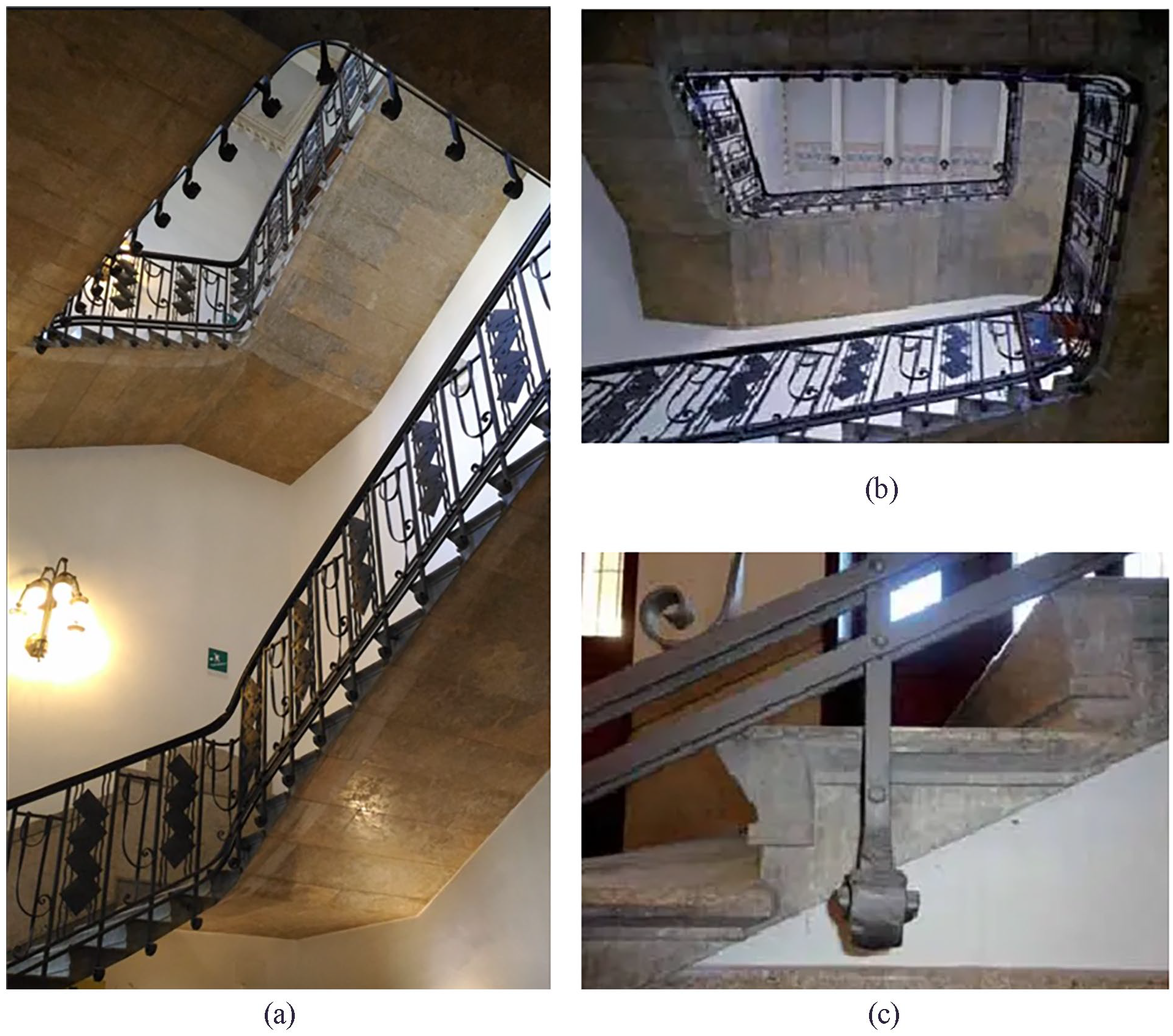
Pictures of the main staircase of the Palazzo delle Poste (Trapani, 1924): (a and b) down-top view of the stair; (c) close-up showing the stereotomy and technological details of the steps. (courtesy of Scalvedi and La Grassa 35 ).
The main staircase serves three storeys with three ramps between two storeys and is set into a rectangular wall box (see Figure 3(a)). The two parallel ramps have an overhang of 1.70 m, and reach two intermediate landings, made from the juxtaposition of two large stone slabs with rounded corners, which include the smaller transverse ramp, having also an overhang of 1.70 m. The single step, although having a serial shape, has a curvilinear outline apt to contain the rebate of the step above, with a thickness of the contact area that reaches 6 cm, thus considerably greater than the torus visible along the lateral edge (see Figure 2(c)).

Main staircase of the Palazzo delle Poste (Trapani, 1924): (a) plan section and (b) view of the i-th step with the local reference system.
This example, similar to the one considered by Heyman,
27
contains all the elements necessary to demonstrate our graphical equilibrium analysis and can be adapted for more complex case studies. Each of the steps shown (Figure 3(a)) is made of a monolithic block of dimensions

Axonometric view of one of the ramps of the staircase of Figure 3.
An old-new strategy to assess the equilibrium of masonry structures
There is a way of looking at the equilibrium of structures that can be traced back to Hooke’s well-known anagram on chains and the equilibrium of arches—Ut pendet continuum flexile, sic stabit contiguum rigidum inversum. 5 In more general terms, this way can be thought of as Strut-and-Tie models. 36 An exemplification of the Strut-and-Tie method in the context of masonry equilibrium is the Thrust Network Analysis (TNA).37–41 The basic idea of the method is to devise within the body of the structure a truss made of 1D elements capable of transmitting the applied external forces (usually represented by the weights of the structure and superstructure) to an appropriate foundation capable of supporting them.
According to this interpretation, the thrust polygon, which can be constructed as a possible funicular polygon of equilibrium of the interaction forces between the stair elements, can be interpreted as a 1D structure on which the external forces act, and stresses are concentrated. In the case of masonry, which is assumed to be unable to transmit tensile forces between its elements, such a structure, must be purely compressed by the loads. In the case of a masonry arch consisting of elementary ashlars, such an interpretation of the thrust line as a structure within the structure is due to Rankine, 42 who called it the “Linear Arch.”
The equilibrium of open-well masonry staircases has already been analyzed using Linear Arch Static Analysis (LASA).43–46 In this method a strut and tie type of approach is adopted to seek the equilibrium of the structure by inserting within the masonry one or more Linear Arches represented by generally non-planar smooth curves on which the vertical loads acting on the structure, are lumped as loads per unit length. These Linear Arches transmit the loads to the supports through compressive normal stresses, thus proving the stability of the structure based on the Safe Theorem of Limit Analysis. One of the key ideas arising from this Linear Arch static analysis approach is that the equilibrium of a spatial curve can be decomposed into two plane analyses obtained by projecting the Linear Arch onto the “planform” (the horizontal plane) and onto a vertical plane. In the case where the curve is parameterized with the arc length along the projection of the curve onto the planform, a more convenient choice for the vertical plane is represented by the development into a plane of the vertical cylinder containing the spatial curve.
The idea of working with forces projected onto the planform is similar to that proposed by Pucher for membrane analysis. Pucher’s intuition, 47 leads to an effective formulation of membrane equilibrium. Indeed, the choice of the projected stresses as the primary variables makes the surface equilibrium problem of the structure independent of the surface geometry and decoupled from the transverse equilibrium problem which it depends upon. This idea is also at the basis for the Membrane Equilibrium Analysis (MEA), formulated for masonry structures in Refs.,48–51 and applied to the design of new structures, 52 and masonry spiral stairs.53–55
In the case of plane arch equilibrium, the projected stress is defined by the thrust force, and the counterpart of the continuum approach associated with the construction of the pressure curve (i.e. thrust line) is represented by the discrete approach defined by the graphical construction of the funicular polygon of the successive resultants of the internal contact forces.
Using a discrete approach, we construct a statically admissible stress state based on the identification within the structure of a purely compressed one-dimensional space polygonal structure capable of transferring the vertical forces applied to it to the supports (in the case of the stairs: the perimeter walls and the ground). The forces acting on the flying stair structure, which can be determined either analytically or graphically, are obtained here using a graphical method.
A graphical method for the assessment of equilibrium in 3D
Geometry, stresses, and loads
From a structural point of view, the step, considered as a 1D element of length
The stress characteristics are the axial internal contact force

(a) forces transmitted to the steps at their free ends and (b) forces nomenclature and possible equilibrium regime.
The reactions transmitted from the wall to the step at the end section, which are denoted with notation
Usually, since the depth of the socket is a small fraction of the length
It is also reasonable to assume that the contact between the step and the walls of the socket be unilateral, thus restraining any possible force
The action that a unilateral constraint of this type can transmit to the step, is represented by a torque
The other reaction forces come from the contact of the step with other steps (or with the landings) along the contact line between one step and another. In some cases, this contact is punctual and occurs only at the free end. In others, it may occur at one or more points, or it may be distributed along the entire line. In the equilibrium analysis that follows, we assume that the contact occurs only at a discrete number of points located along the contact line. The mutual reaction force transmitted to the contact points can occur in all directions subject to restrictions due to the one-sided nature of the contact, the actual size and orientation of the joint, and the friction coefficient between the steps and between the steps and the wall.
Possible equilibrium scenarios for open-well stairs
We introduce and illustrate a simple graphical technique which is a geometrical version of the method put forward in Angelillo et al. 44 and Olivieri et al. 46 described in Section 3. The main idea is to identify a 1D space polygon inside the structures capable of transferring the vertical forces applied to it to the perimeter walls and to the ground. This can be achieved by introducing and using a new graphical approach.
The equilibrium problem under the action of the specified vertical loads is reduced to two plane graphical analyses obtained by projecting the one-dimensional polygonal structure onto a vertical plane, called π, and onto the horizontal plane (the planform), denoted
As mentioned in Section 3, open-well staircases, also called cantilevered staircases usually do not cantilever from the walls; their equilibrium depends on the interaction forces between one step and the next, which grow from top to bottom and ultimately transfer the load to the ground. Collapses of open-well staircases in which the lower ramp or only a few lower steps had been removed in the course of restoration or renovation, have been reported in Price and Rogers. 57
The approach to guarantee the equilibrium of this type of structure has been described in Refs.27,58,59 This mechanism of stress transmission, which we refer to as Mode 1, is concisely described next.
The analysis refers to the particular case of Figure 3, and a ramp extracted from it and depicted in Figure 4.
We consider the following dimensions:
The equilibrium of the vertical forces transmitted to the free ends of the steps of the ramp of Figure 4 taken from the stair depicted in Figure 3, is analyzed in the vertical plane
The 10 triangles of Figure 5(b), representing the cross section of the steps, appear to be connected to one another by internal hinges (the dots in the same figure), the lowest step by an external hinge at the bottom edge (n° 10). In contrast, the top step is considered free of constraints at the upper right vertex (n° 0) and subject to a known (possibly zero) purely vertical force
Neglecting any other type of constraint present in the step except the restriction that each step rotates about a plane orthogonal to the wall, and that restricts the rotation of the triangles of Figure 5(b) into their plane, we add 10 constraints on rotation about the axis
The 20 reaction components
Referring to Figure 5(b), defined


while the step n sustains a net vertical load equal to

Based on this equilibrium solution, we can evaluate the torque sustained by each step. A computation related to a staircase of tread

Considering that for the ratio

This value of
A different mechanism for transferring forces to the wall and ground that does not involve the linear growth of torque with height produced by Mode 1, is Mode 2, described below.
The polygonal Linear Arch represents a kind of spatial funicular polygon whose stability is ensured by some additional compressed elements (the struts). In the conventional construction of the funicular polygon for an arch, the loads and their lines of action are specified, while the shape of the polygon, that is, the ordinates of the polygon nodes together with the thrust force, are the unknowns. In contrast, in the approach we propose here, the shape of the spatial funicular polygon representing the path of the internal forces transmitted through the steps is assigned together with the vertical forces transmitted to it by the steps, while the direction of the compressed connecting struts and the forces transmitted by them are considered as unknowns together with the thrust forces. The thrust forces, denoted
If the thrust in the first side of the polygon is given, the unknowns are then the
The construction of the Linear Arch, shown in Figure 6(a), can proceed by starting from the assignment of an appropriate polygon, called polygon 1, in the planform. This choice is arbitrary, and we can alter it (possibly through optimization) to obtain different results.
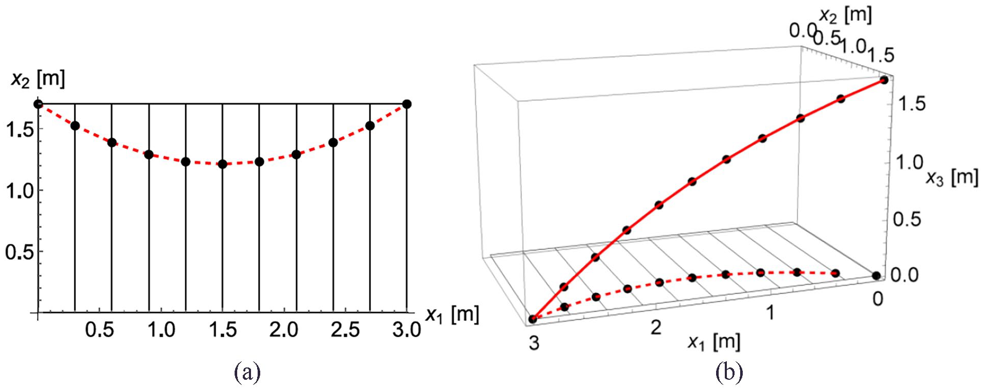
(a) projection of the Linear Arch (polygon 1) and of the nodes onto the planform; (b) 3d view of the Linear Arch, nodes and its projection (polygon 1, dashed).
Specifically, the position of the nodes shown in Figure 6(a)) and the corresponding polygon has been obtained by assuming a distribution along a parabolic arc of the nodes from 0 to 10 and considering a rise of the arc in the horizontal plane
The specific shape of the spatial funicular polygon representing the Linear Arch that is considered here, is then generated by placing the vertices of the polygon (the nodes of the structure) at the interface between the steps. The resulting shape is shown in Figure 6(b). The sides of the Linear Arch are denoted
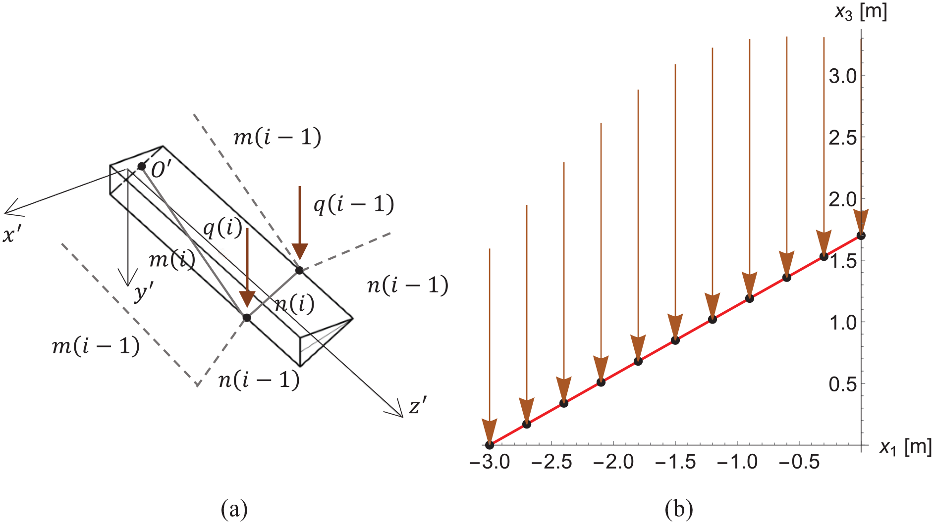
The Linear Arch as a spatial funicular polygon. (a) 3d view of the detail of a step; in continuous line the “tie ro,” relative to step i, dashed the “truss element,” relative to the adjacent steps; n(i) denotes the sides of the Linear Arch, m(i) the horizontal connecting “truss element.” (b) projection of the Linear Arch into the vertical plane π (polygon 2) with the indication of the forces (of length proportional to their values) due to the weight transmitted by the step.
The vertical loads

As for the loads

The determination of the solution for the case at hand will be obtained graphically by referring to the values of the forces
The graphical solution proceeds by preliminarily addressing the equilibrium in the vertical plane, that is, on a polygon that is the projection of the Linear Arch into the plane π (parallel to the
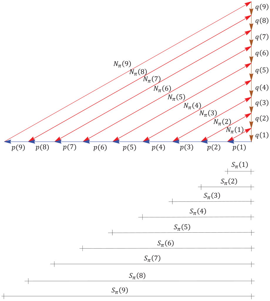
Diagram of forces corresponding to polygon 2.
The approach proceeds as follows:
The forces are ordered by taking them from the funicular polygon 2 of Figure 7(b) from left to right and arranging them sequentially from top to bottom. In Figure 8 it has been assumed:
The last force
The horizontal forces

Once the projected thrusts
The so-obtained normal forces
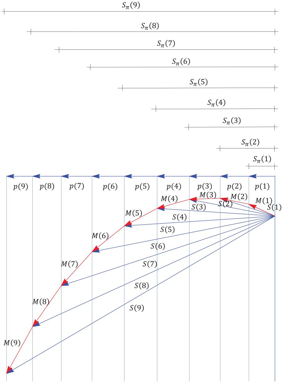
Force diagram of the thrust forces

Forces transmitted from rods
From Figure 10, one can see that, in this case, the horizontal forces transmitted by the rods
In the present case the maximum moment is transmitted to the first step:

Such a value, which is one order of magnitude less than the one produced in Mode 1, is reduced if the effect of the load coming from the landing or produced by the weight of the upper ramps is considered. This is studied next.
We repeat the analysis on the same staircase ramp (the third one) by assuming the same arch shape in projection. Here, we assume

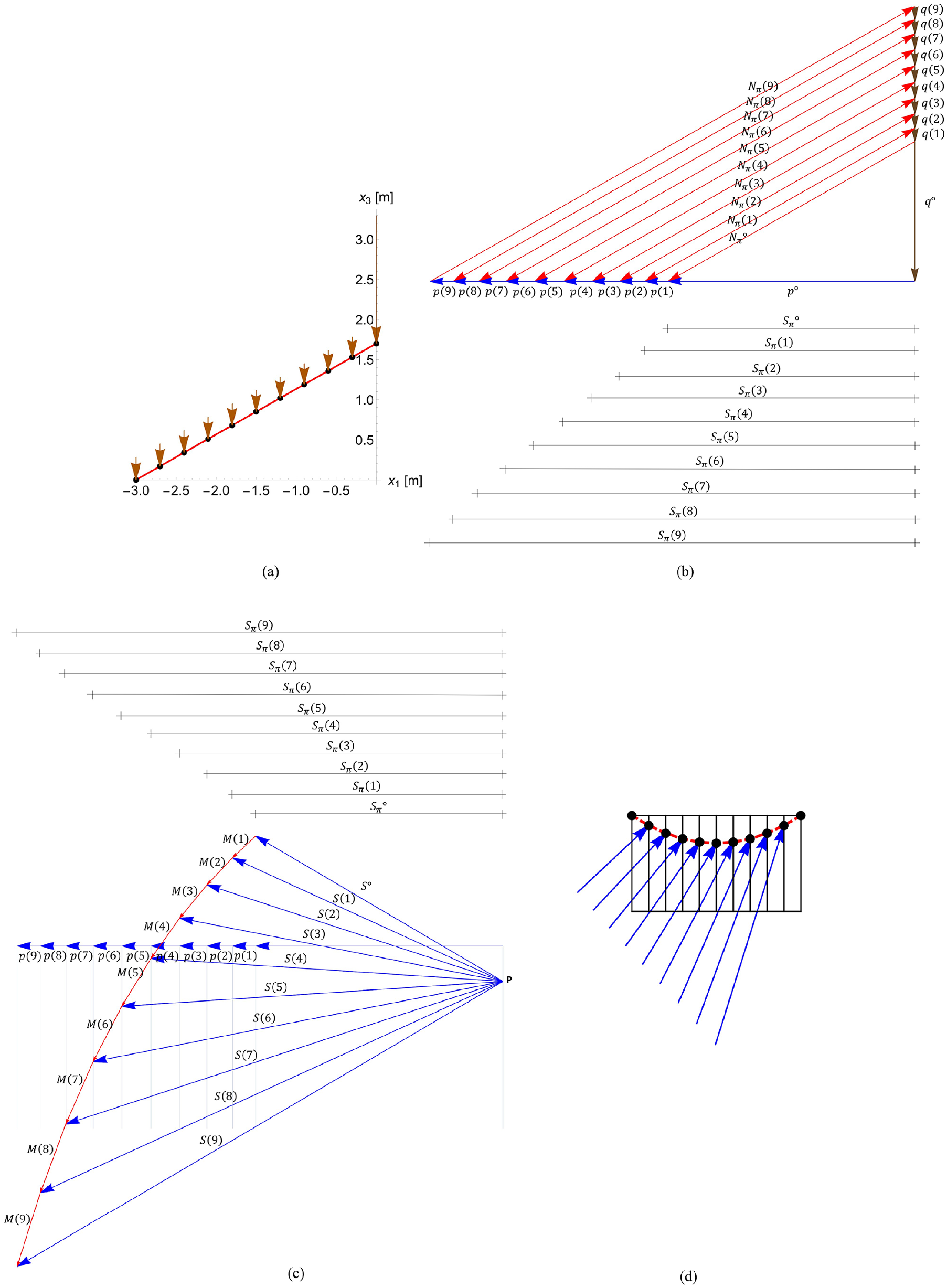
Third part of the stair where q° = 19 kN: (a) Funicular polygon and (b) diagram of corresponding forces, (c) projected normal forces
The flowchart in Figure 12 provides a clear overview of the steps involved in the Mode 2 procedure. It displays a well-organized sequence of events, making the process easy to follow and understand, contributing to the transparency and reproducibility of the research.
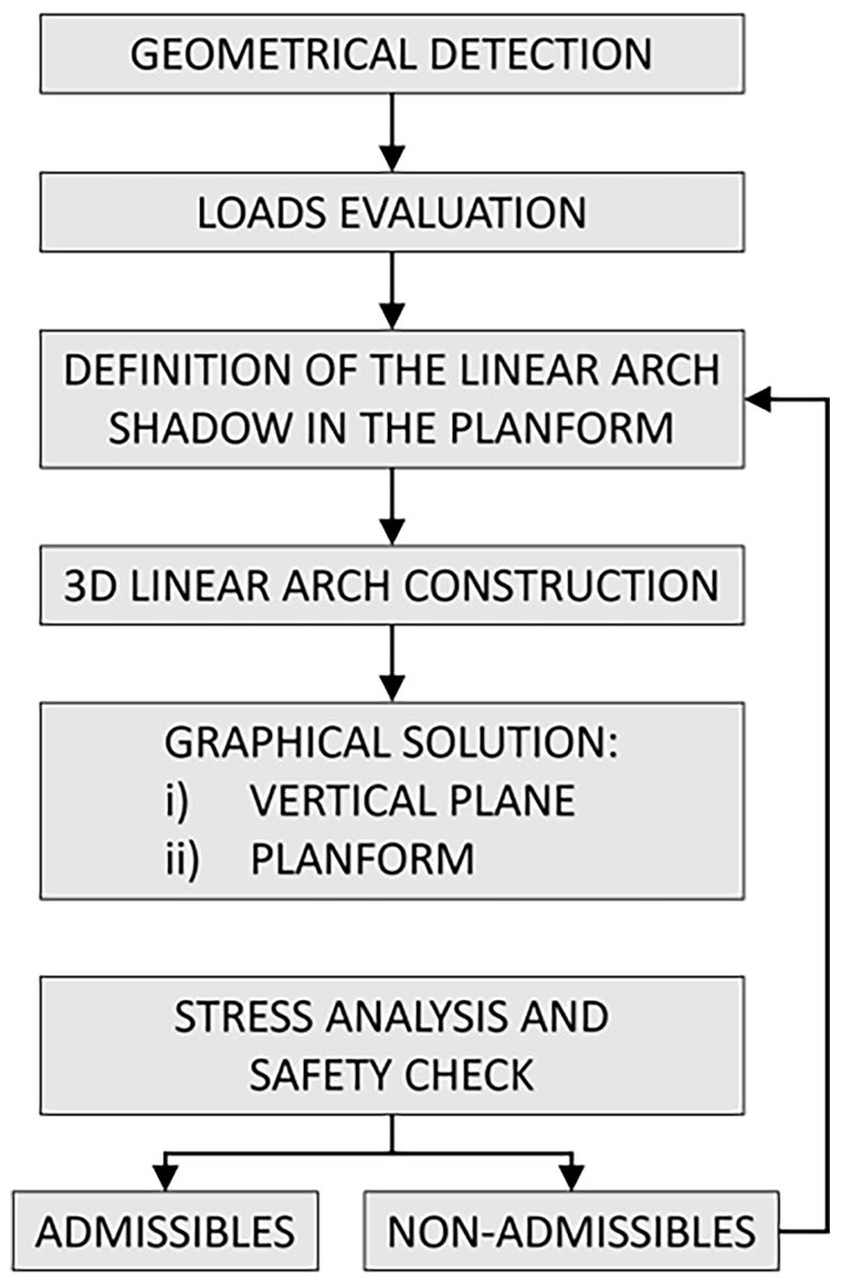
Flowchart of the Mode 2 procedure.
Conclusion
We have presented a new graphical approach for assessing the stability of open-well staircases and have applied it to the main staircase of the Palazzo delle Poste (Trapani, 1924, designed and constructed by Francesco La Grassa). This stone staircase has a rectangular plan and is composed of monolithic stone steps built into the wall.
The presented approach extends the existing 2D funicular polygon approach for assessing arch equilibrium into 3D and represents the graphical counterpart of Linear Arch Static Analysis (LASA). This graphical approach allows to graphically compute equilibrium in compression for arches and curves, which can be non-planar. The method finds robust application in the case study of masonry staircases made of monolithic blocks, giving an alternative for equilibrium to the pure torsional solution. This alternative equilibrium regime guarantees to keep the tangential stresses into the stone material composing the steps within reasonable limits when the length of the stair exceeds one coil.
A graphical approach in solving structural problems, even in today’s age of advanced numerical tools, allows the engineering practitioner, researcher or student to visually understand the effect of varying parameters in the definition of form and its effect on the membrane behavior in a shell without resorting to complex numerical modeling. This method also allows for evaluation using hand calculations without relying on computer software. This might be useful in the context of preliminary evaluation or evaluation on-site. The graphical approach offers a simple and effective way to understand the forces at play, making the structural assessment intuitive and straightforward.
The main result of the equilibrium analysis conducted is that the linear growth of the torsional moments with height, predicted by Mode 1, is eliminated using Mode 2, in which the torsional moment does not increase with height, while the internal axial forces in the connecting rods
Compression is the most favorable stress regime for masonry, but, of course, also an excess of compression must be kept under control. To this end, combining Mode 1 and Mode 2 could be of interest.
In particular, in the case study we considered, we see that for a staircase of 10 steps, there are
Footnotes
Declaration of conflicting interests
The author(s) declared no potential conflicts of interest with respect to the research, authorship, and/or publication of this article.
Funding
The author(s) disclosed receipt of the following financial support for the research, authorship, and/or publication of this article: The research was partially funded by the ROBELARCH, a Princeton University Global Collaborative Network.
