
Abstract
The purpose of the present paper is to demonstrate how the script components of Grasshopper, the user-programming platform of the geometry program Rhinoceros 7/8, can be used to create a software tool for the generation of two complex semi-regular polyhedra, namely, the snub dodecahedron and its dual, the pentagonal hexecontahedron. The snub dodecahedron is an Archimedean polyhedron whose geometric construction is not as simple or direct as that of other polyhedra. The dual of this polyhedron is the Catalan polyhedron known as the pentagonal hexecontahedron, a convex polyhedron with 60 identical, axially symmetric, semi-regular, pentagonal faces. The intricacy of deriving and specifying the geometric particulars of these two polyhedra might be a reason for their infrequent application in dome-like architectural envelopes, such as the “Amazon Spheres” in Seattle (2018). A numerical method for the geometric specification of the snub dodecahedron based on the regular icosahedron is used in this article to illustrate its formulation in Grasshopper (GH). The successive GH implementation of the duality principle to obtain the pentagonal hexecontahedron completes the formulation exercise. Here, the geometric construction method and its algorithm, as well as the data organization and its handling within the data tree structure in Grasshopper, pose the actual challenge for an efficient formulation. The practical outcome of the present discussion is provided by the GH-script that generates the mentioned polyhedra, which can be used in further design and construction processes.
Keywords
Introduction
Classical space structures in Architecture and Structural Engineering are spatial arrangements of bars, in the form of tubes, struts, or beams, that are usually interconnected at their ends, often with prefabricated joints, to build larger structural or architectural elements, such as roofs and domes, that shelter and enclose human activities.
Polyhedral geometry lends the geometrical design of classical space structures a rich repository of basic geometric constructs and complex configurations. The regular Platonic solids, tetrahedron, cube, and octahedron, constitute the primary morphological basis of regular space structures, where regularity is the key aspect that conditions an economical and efficient structural and construction system built out of very few basic components. Regular space structures deploy in space more like a surface or blanket. The two remaining Platonic solids, the dodecahedron and the icosahedron, are not quite suitable seeds for filling space with repetitive generative units, but they provide three-dimensional, highly symmetrical frameworks to develop dome-like space-enclosing structural systems, such as the so-called geodesic domes, with a minimum number of basic components.
The set of 13 semiregular polyhedra, known as Archimedean solids (https://en.wikipedia.org/wiki/Archimedean_solid), extends the morphological potential of regular space structures by relaxing the canonical regularity of Platonic-based configurations. While a Platonic solid has only one type of regular face, one edge length, and a single vertex configuration, an Archimedean solid has at least two types of regular faces, only one edge length, and one typical vertex configuration, where the latter refers to the arrangement of faces around a vertex in a polyhedron.
The further development of polyhedral geometry over the centuries led to the discovery of the Catalan solids (https://en.wikipedia.org/wiki/Catalan_solid) in the second half of the 19th century. Just as the Platonic solids have duals, so do the 13 Archimedean solids, thus yielding 13 duals, which are named after the Belgian mathematician Eugène Charles Catalan, who discovered, described, and classified them. Unlike an Archimedean solid, which has a single vertex configuration, a Catalan solid has at least two distinct vertex configurations, at least two distinct edge lengths, but a single face type, which is, in general, not a regular polygon. Nonetheless, Catalan solids inherit their high symmetry from the Archimedean solids.
In Architecture, Engineering, and 3D Art, Archimedean and Catalan polyhedra together further extend and enrich the vocabulary for design objects based on the Platonic solids, which, as mentioned above, tend to be “too” regular and rigid. The Archimedean and Catalan polyhedra, which have at least two distinct faces and, in some cases, local asymmetries, loosen the strict regularity of the Platonic solids, introducing movement and dynamics into a design without compromising the advantages of highly symmetric configurations. Furthermore, among the 13 Archimedean solids, two are “chiral,” meaning that they lack mirror symmetry and therefore possess distinct “left” and “right” forms. These solids are the snub cube (https://en.wikipedia.org/wiki/Snub_cube), which has 6 squares and 32 equilateral triangles, and the snub dodecahedron (https://en.wikipedia.org/wiki/Snub_dodecahedron), which has 12 regular pentagons and 80 equilateral triangles. The term “snub” denotes a twisting or rotation of certain faces relative to others within the polyhedron. For example, in a “left” snub dodecahedron, the pentagonal faces exhibit a leftward rotation relative to the remaining faces. As with all Archimedean polyhedra, each chiral form possesses a single edge length and a uniform vertex configuration.
Despite the above-discussed morphological potential, real-life structural design of spatial structures has shown that only a few geometric configurations, out of the universe of all possible configurations based on regular and semi-regular polyhedra, have been used to materialize spatial structural systems. A main reason is certainly their straightforward translation into economical construction systems. However, the need to escape the monotony of classical regular space structures has encouraged designers to seek practical applications among the semi-regular polyhedra. One particularly interesting polyhedron, namely the Catalan solid known as the pentagonal hexecontahedron (https://en.wikipedia.org/wiki/Pentagonal_hexecontahedron), was chosen for this article to illustrate the successful search for a dynamic, apparently simple but intriguing form that can be used to design architectural dome-like envelopes. Intriguing because its exact geometric constitution cannot be easily understood by inspection or through the classical tools of Euclidean or descriptive geometry, even by the most geometrically versed specialists. This polyhedron is certainly the most complex of the Catalan solids, with its chiral (non-symmetric) nature, featuring a unique type of semi-regular, axially symmetric (isosceles) pentagonal face, arranged to build a quasi-spherical complex of 60 identical polygons, with only two different edge lengths and two distinct vertex configurations.
A rare built example based on the pentagonal hexecontahedron is the “Amazon Spheres” (Arch. NJJB, 2018) in Seattle, whose primary steel structure geometry is based on this polyhedron, as shown in Figure 1, right. Here, a typical isosceles pentagon of the pentagonal hexecontahedron, highlighted in red, encloses a typical primary steel unit. A general description of the project can be found in ref (https://www.structuremag.org/article/amazon-spheres/, pp. 26–28). Another built example is a sculptural glass pavilion featuring detailed, colorful stained-glass illustrations by artist James Jean, in collaboration with NOUS Engineering, California, USA, 2025, which is awaiting public release. Further examples, on a smaller scale, can be found on the Internet in the form of decorative 3D hanging mobiles or lamps.
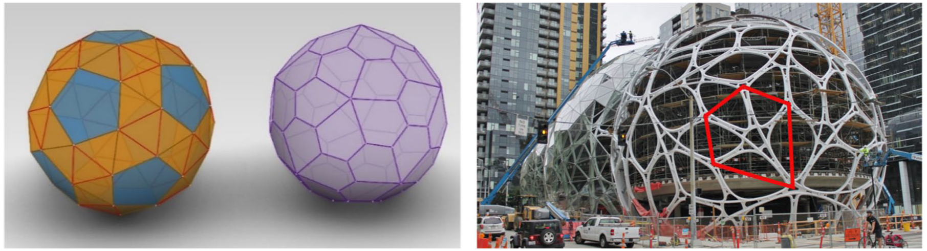
Left: The snub dodecahedron and its dual, the pentagonal hexecontahedron. Image: Jaime Sanchez. Right: Primary structure of one of the Amazon Spheres, Architect: NJJB; Engineering: MKA; Seattle, USA.
In the 19th century, various mathematicians systematically studied polyhedra. Still, the explicit Euclidean constructions for the snub cube and the snub dodecahedron remained unsolved, because the exact specification of their geometry involves solving certain cubic equations. By extension, the classical Euclidean solution for their duals, namely, the pentagonal icositetrahedron and the pentagonal hexecontahedron, remained equally pending.
Thus, the exact geometric specification of chiral polyhedra had to wait until the 20th century, when advances in geometry, algebra, numerical methods (such as the finite element method), algorithmic techniques, 3D and CAD modeling, computer graphics, and programming languages—driven by rapidly developing computer technology and strong synergetic interaction—converged in the field of what is now known as Computational Design in Architecture and Engineering. Consequently, research, modeling, and design related to polyhedral geometry belong to the field of computational geometry design.
Here, a widespread software tool among today’s “geometry designers” is the program Rhinoceros 7/8, which has specialized extensions, known as add-ons, plug-ins, and built-ins, triggered by special modeling or creation requirements of a design task. In particular, the user-programming built-in platform known as Grasshopper offers the possibility of customizing solutions for a problem in an intuitive, straightforward, clear, and efficient way. The subsequent main sections of the article illustrate how the language components of Grasshopper can be used to implement the generation of the snub dodecahedron and its dual, the pentagonal hexecontahedron, as 3D line and face models, which can be used in further design and technical processes. Issa, 1 (https://discourse.mcneel.com, https://www.grasshopper3d.com) provide the theoretical background and the software tools used to tackle the present script formulation task.
From the various existing methods specifying the geometry of the snub dodecahedron, a geometric construction method based on the regular icosahedron 2 is adopted in this article to illustrate its formulation in Grasshopper (GH). More than translating the geometric construction method’s formula into adequate GH-script “components,” the geometric construction strategy or algorithm, on the one hand, and the data organization and its handling within the data tree structure in Grasshopper, on the other hand, pose the actual challenge to reach an efficient formulation. The practical value of the present discussion is evident in the resulting software tool, which enables the modeling of polyhedra and the generation of geometric data that can be utilized in subsequent design and construction processes.
The formulations and algorithms presented in this article are working proposals. Thus, they are not unique final solutions but might serve as an incentive to improve the mathematical method, the geometric construction strategy or algorithm, and the GH implementation.
The vertices of the snub dodecahedron
This section identifies the key aspect of the geometric definition of the snub dodecahedron SD, that is, the mathematical specification of the vertices’ positions of this polyhedron on the faces of a regular icosahedron that has been taken as “parent” or reference framework, following the method introduced by Gheorghiu and Dragomir (G&D), 2 specifically in figure 232d. Figure 2 summarizes the method, which includes an equation of the third degree, whose only positive root specifies the position of a subdivision point on an edge of a triangle in the parent regular icosahedron.
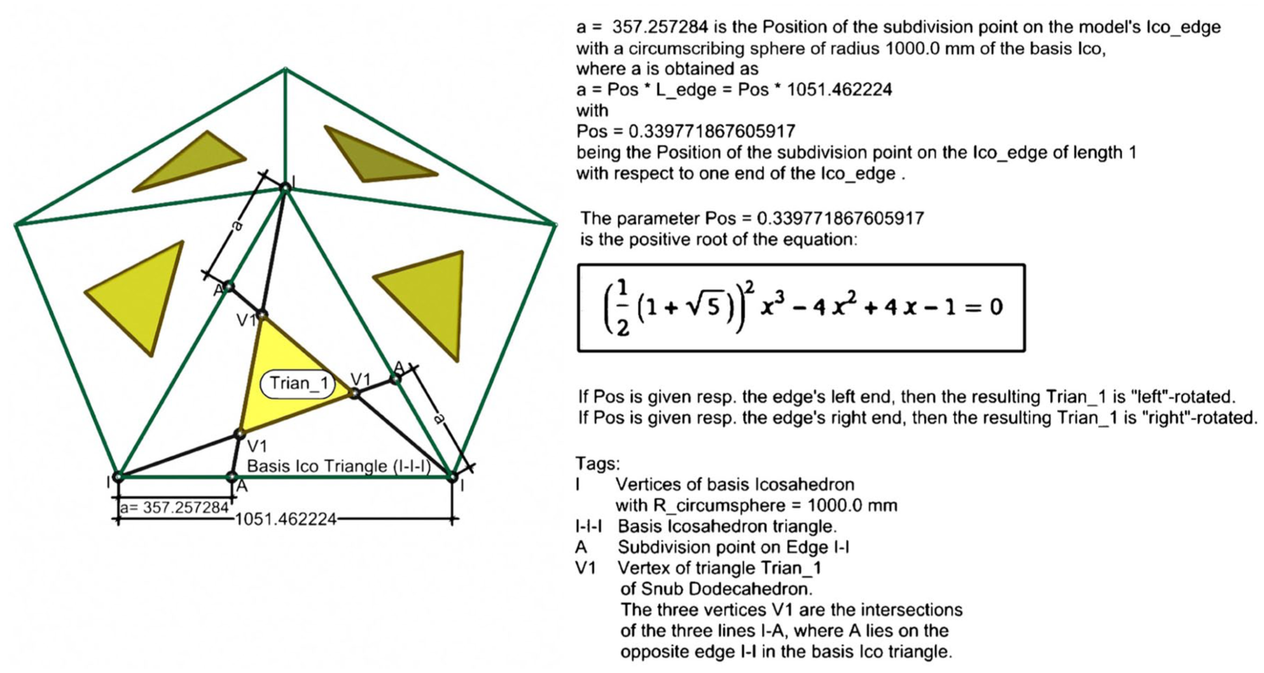
Construction principle of the left rotated SD-triangle Trian_1 on a parent ico_triangle, based on the Gheorghiu and Dragomir method in Gheorghiu and Dragomir, 2 drawing: Jaime Sanchez-Alvarez.
For the present GH-formulation, this positive root has been obtained with the equations’ solver of the computational knowledge engine “wolframalpha.com” (http://www.wolframalpha.com). According to G&D the snub dodecahedron can be easily constructed out of this ico_edge subdivision point or “key-point.” Thus, a geometric construction method, proposed by the author of the present article, is briefly described in the following three steps: (a) The key-point coming out of the G&D method is firstly mapped on the three edges of the typical parent ico_triangle; (b) The resulting three subdivision points are then used to draw three lines, where a line goes from a key-point to the opposite vertex on the parent ico_triangle; (c) The three resulting lines naturally intersect at three points, which in turn define the vertices of the smaller (left-) rotated triangle Trian_1 of the SD on the typical parent ico_triangle. The numerical specification of the basic SD_triangle’s vertices is complete, and it is incorporated at the very beginning of the GH-formulation as part of the initial input data.
The Grasshopper formulation of the snub dodecahedron
An overall view of the GH-script that generates the snub dodecahedron SD is given below in Figure 3. The GH-script has been extended to create the “dual” polyhedron, that is, the pentagonal hexecontahedron. The “canvas” or programming area of the GH-script has been divided into various sections containing the main stages of the construction procedure, namely, sections A to F for the snub dodecahedron, and section G for the pentagonal hexecontahedron. Due to the extension of the GH-script in Figure 3 the component names and texts are not legible, because the purpose here is to give a first general impression of the whole script. The script sections mentioned above will be discussed in detail in the sequel and presented there on a larger scale.
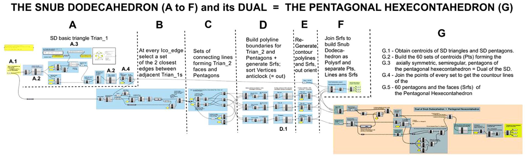
Grasshopper script for the snub dodecahedron and its dual, the pentagonal hexecontahedron (left form). Overall view.
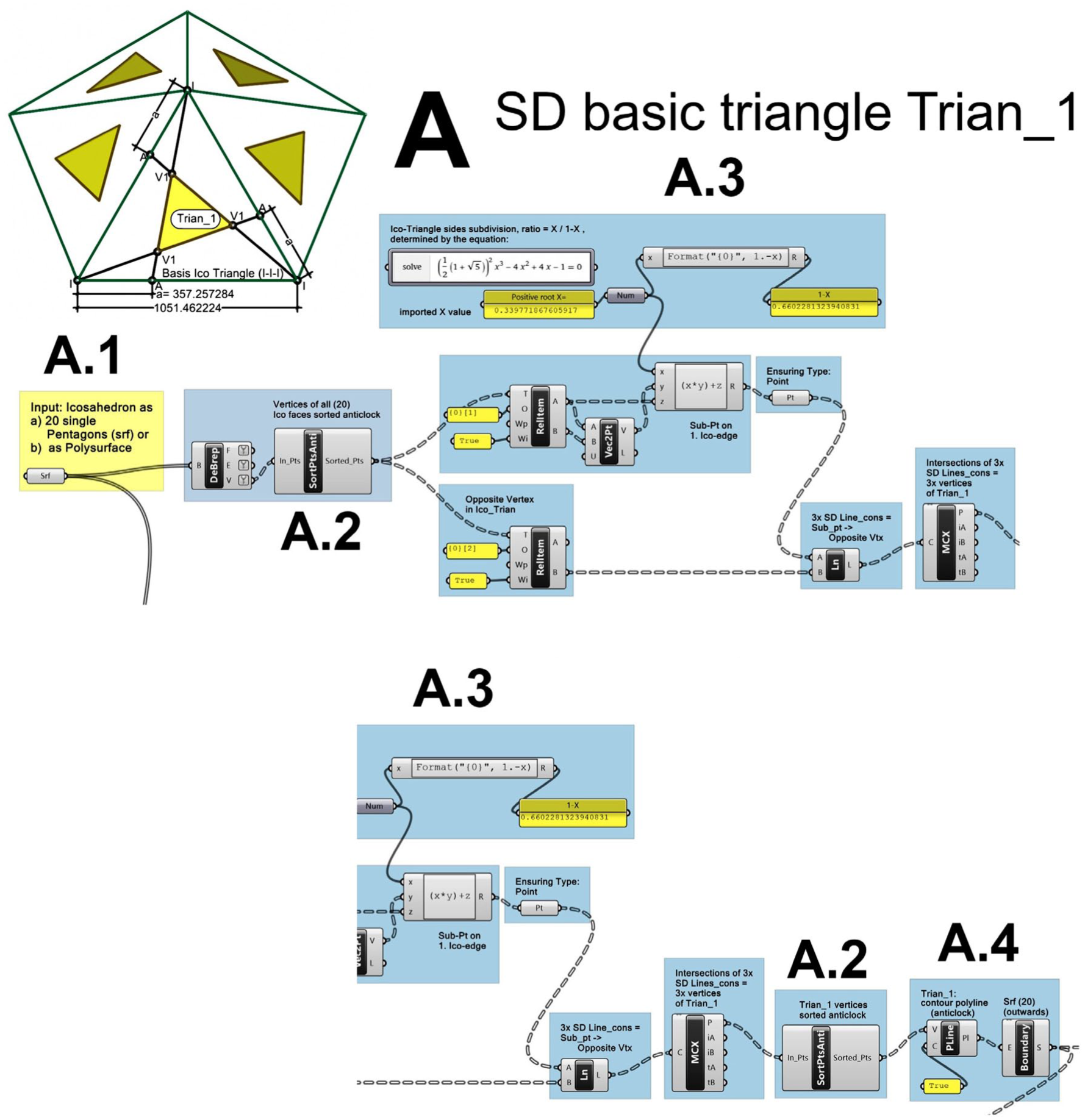
A: SD basic triangle Trian_1
Figure 5: A.1. Input: The parent icosahedron Ico can be read from the Rhino modeling space either as a set of 20 individual triangular surfaces or as a polysurface. For convenience, it is recommended to set the Ico, which is a point-symmetric body, centered with respect to the origin (0,0,0), although it is not essential for the GH-script.
Figures 4 and 5: A.2. In order to reorganize the object’s components in a consistent form that repeats for all 20 Ico triangles, the read surfaces are deconstructed into faces, edges, and vertices. The resulting 20 sets of 3 vertices (Pts) are then passed on to the SortPtsAnti-component to be ordered, set by set, anticlockwise. For every set of three points, an axis is defined from the center of the parent Ico and the average point in the set. The points are then ordered around the defined axis according to their increasing angle with respect a reference line between the average point and the first point in the set. The points ordered in this way are considered to be “outwards”-oriented. The image in Figure 4 top shows two arbitrary triangular faces, 10 and 18, of the parent Ico with the sorted indices of the vertices for every triangle. The index 0 indicates the first point, the arrowed lines indicate the order of the sequence, the last point has the index 2. The sorting procedure has been placed into a so-called “cluster” for use as a GH-component at other stages in the script.
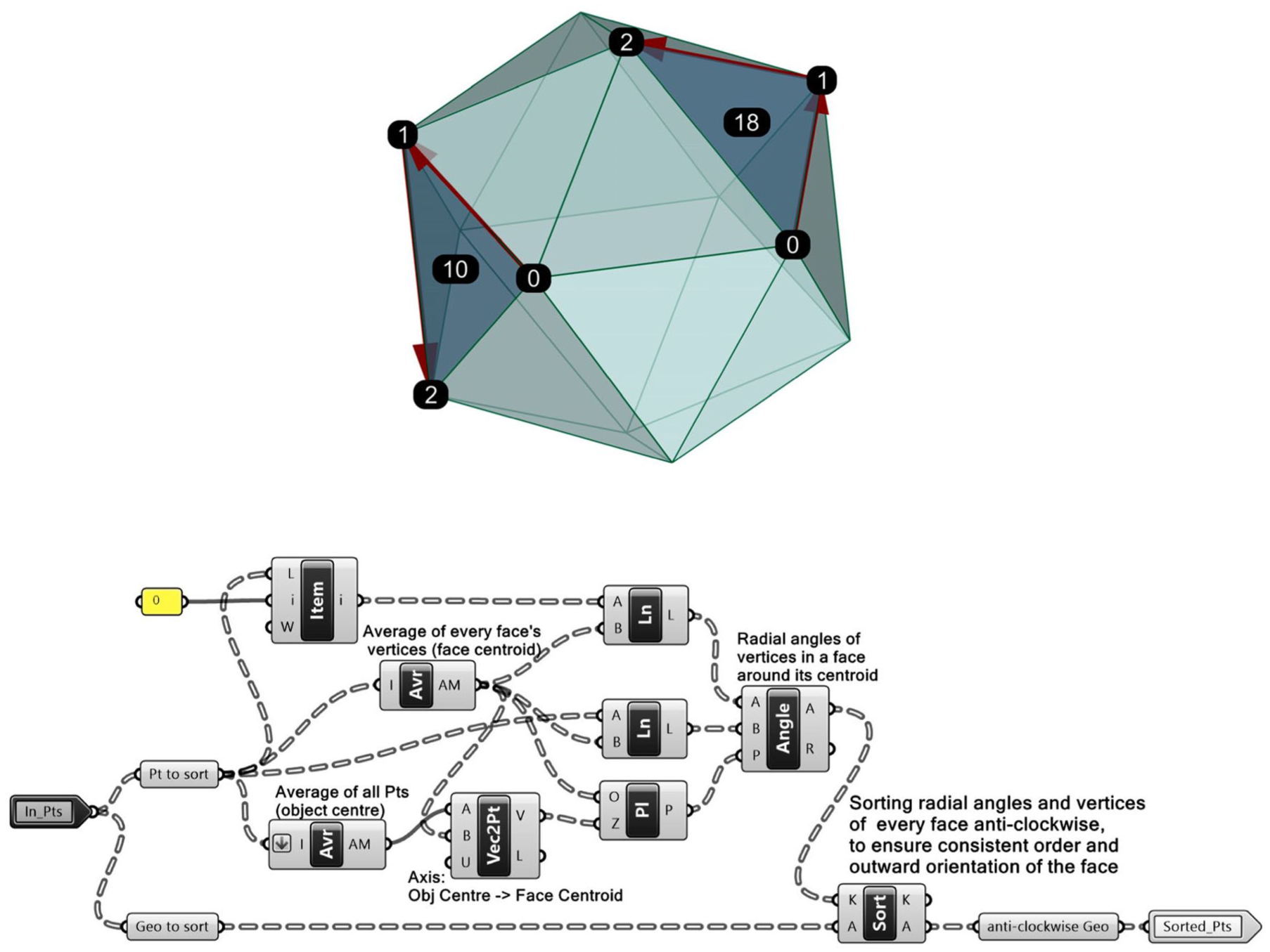
A.2: The GH-script in “cluster” SortPtsAnti to sort points anticlockwise.
The basic triangle Trian_1 of the snub dodecahedron SD.
Figure 5: A.3. The actual specification of the basic triangle Trian_1 of the SD is summarized in Figure 5. Here, the unique value of the Ico_edge original subdivision “key-point” after G&D is given in the script as a constant, which is scaled to position on the typical real Ico_edge to get the “key-points” on the three edges of the parent Ico_triangle from the Rhino model. Through the convenient index increment specification in the Relative-Item-component (RelItem), it is possible to repeat set-wise the positioning of the three Ico_edges key-points in all triangles of the parent Ico. This reproduction effect is extended to the creation of 20 sets of three intersecting lines on the 20 parent Ico triangular faces. The actual line intersections are performed with the Multiple-Line-Intersections-component (MCX), which is sequentially applied to the previously generated 20 sets of to-be-intersected lines.
Figure 5: A.4. The intersection points in every set are then passed to the SortPtsAnti-component (A.2) to guarantee a consistent anticlockwise, outward-oriented, point order. These 3-point sets are, in turn, passed to the Polyline-component (Pline) to generate a series of 20 closed triangular polylines, which are in turn given to the Boundary-component to create the 20 basic, outward-oriented, triangular faces Trian_1 of the snub dodecahedron.
B: The two closest Trian_1 edges at every Ico_edge
Figure 6: A.1, A.4, B. In this section, the two closest edges of the two closest Trian_1s at every parent Ico_edge are firstly identified as part of the relevant lines to build later the triangles Trian_2 in between adjacent Trian_1s.
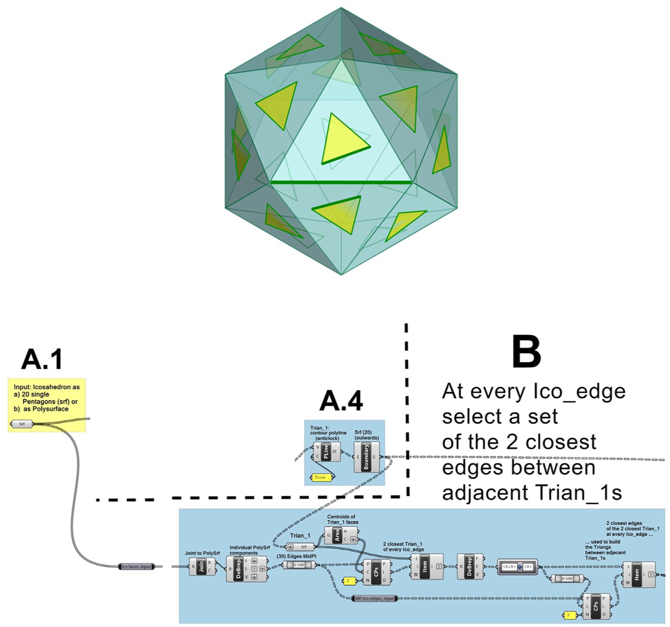
The two closest edges between adjacent Trian_1s at every parent Ico_edge.
C: The connecting lines forming Trian_2 triangles
Figure 7: C. To build the two possible equilateral triangles Trian_2 in between adjacent Trian_1s, it is necessary to make a set with the five lines that build the boundaries of the two mentioned triangles Trian_2 at every parent Ico_edge. One starts with the two closest edges of the two closest Train_1s at every parent Ico_edge determined in section B. These yield two endpoints at either side of an Ico_edge that can be connected in only three ways, that is, with three lines that form the intermediate equilateral triangles Trian_2, as shown in the middle of Figure 7 with three Line-components. To complete the Trian_2 equilateral triangles’ boundaries, there are still two lines needed, namely, the two closest edges of the two closest Trian_1s at every Ico_edge from section B, that is, the two Item-components at the middle, bottom, of Figure 7. The right image of Figure 7 shows the green lines forming the Trian_2s in between the yellow Trian_1s. Some of these new intermediate Trian_2 lines also give rise to the pentagons of the snub dodecahedron.
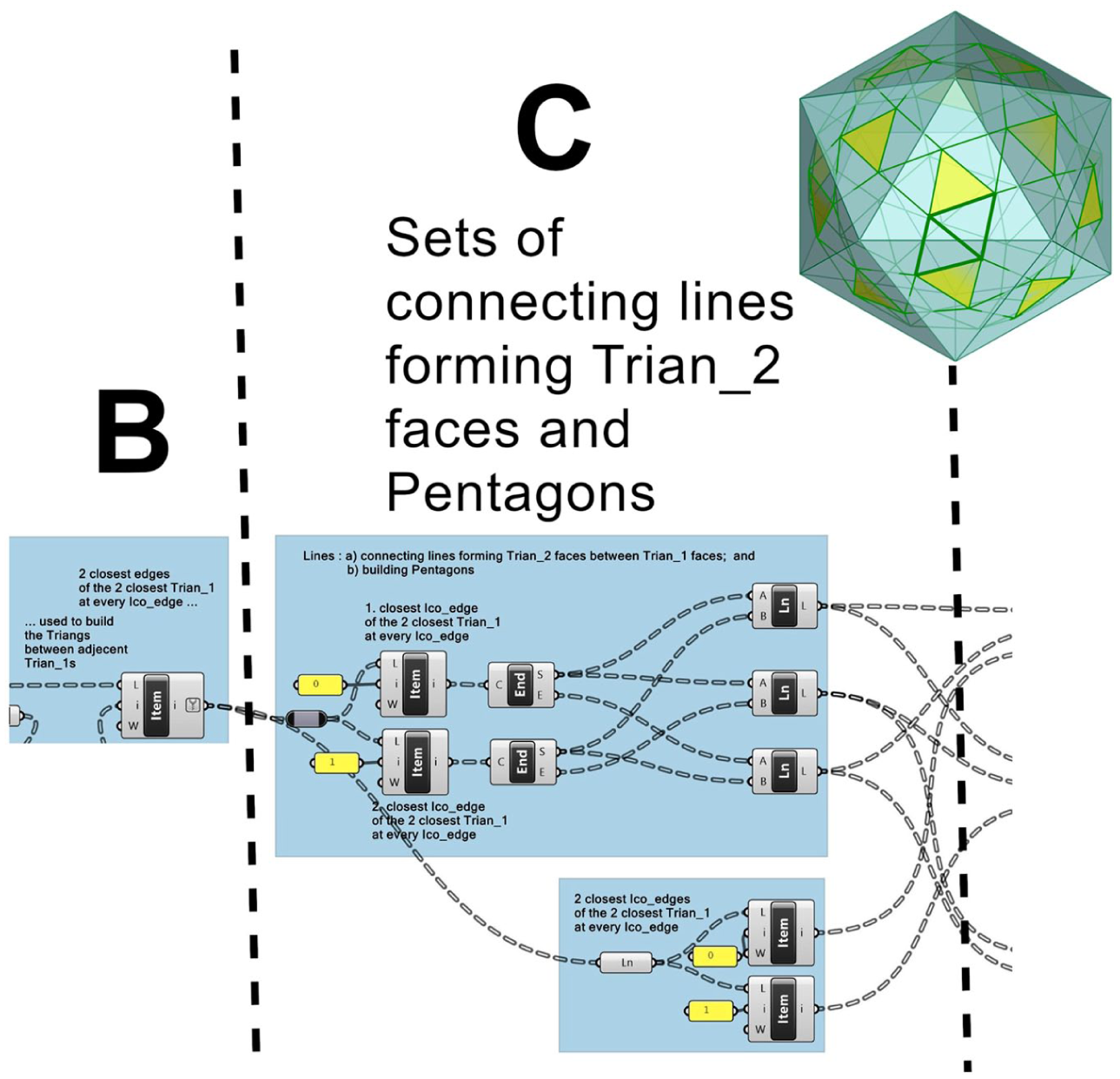
Sets of connecting lines forming Trian_2 triangles and pentagons in between Trian_1s.
D–E: Polyline-boundaries and surfaces for Trian_2s and pentagons
Figure 8: D. The lines from section C are combined to form the 60 polyline boundaries of Trian_2s and the 12 polyline boundaries of the pentagons of the SD. The corresponding surfaces are created with the aid of the Boundary-component. The order and orientation of the generated surfaces’ components, that is, faces, edges, and vertices, is unknown at this stage. To follow the adopted consistent components order, that is, anticlockwise and outwards, the components must be re-ordered starting with the vertices obtained from the Deconstruct-Brep-component (DeBrep) that are subjected to the SortPtsAnti-component introduced in section 3.2 A.2, repeated here below in Figure 8 D.1.

Polyline boundaries and surfaces for Trian_2s and pentagons of the SD.
Figure 8: E. With the re-ordered face vertices, the boundaries for Trian_2s and pentagons are re-generated as anticlockwise, outward-oriented, closed polylines with the PLine-component to be passed on to the Boundary-component to generate in turn the corresponding Trian_2 faces, 30 in red and 30 in magenta, and the 12 pentagonal faces, in blue, of the SD. The 20 initial Trian_1 faces appear in yellow in the polyhedron’s image.
E–F: The individual faces (Srfs) building the snub dodecahedron
Figure 9: E–F. Having gathered the various sets of faces, namely, 80 equilateral triangles and 12 pentagons of the SD in section E, the collection is “Merged” into a single set of objects, which is “Joined” as a polysurface in section F. The reason is that the Join-component takes care of eliminating double objects, mainly coincident face boundaries in the polysurface. The Deconstruct-Brep-component (DeBrep) finally yields the individual 92 faces (Srfs), 150 constant-length edges (Lines) and 60 vertices (Pts) of the snub dodecahedron SD. The image on the right shows all equilateral triangular faces of the SD in a single color, orange; the pentagonal faces in blue; the one-length edges appear as red lines; and the vertices (Pts) as small circles.
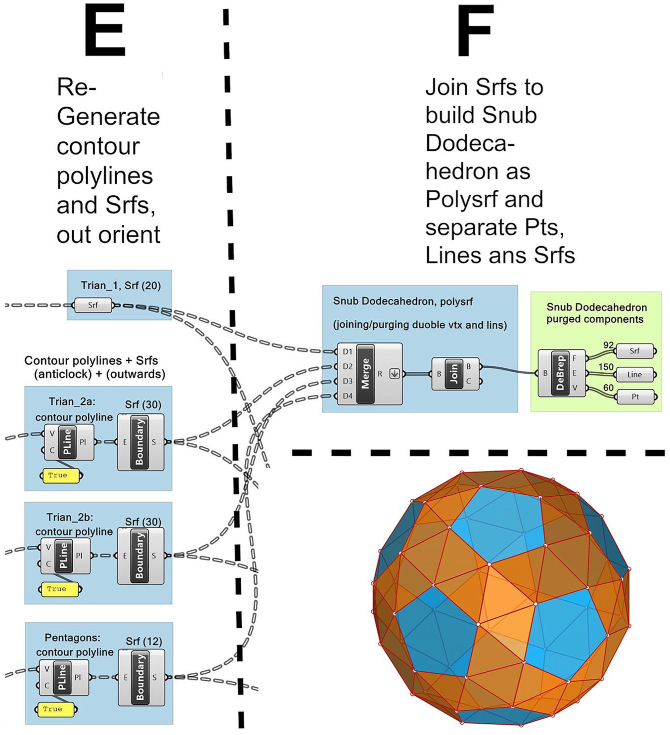
Joining Trian_1s, Trian_2s and pentagons to form a SD polysurface and deconstructing SD in individual faces (Srfs), edges (lines) and points (Pts).
The Grasshopper formulation of the pentagonal hexecontahedron
As it is generally known, the dual of a network or a polyhedron can be obtained by connecting the centroids of its adjacent cells or faces with lines. The sets of lines forming closed cycles define the faces of the dual network or dual polyhedron. In the current GH-script, this procedure is summarized in five stages, grouped in section G on the GH-canvas, as shown in Figure 10. The procedure stages are G.1: obtain centroids (Pts) of SD triangles and pentagons; G.2: build the 60 sets of 5 centroids forming the G.3: axially symmetric, semi-regular, also called isosceles, pentagons of the pentagonal hexecontahedron; G.4: connect the five points of each set to produce the G.5: 60 pentagonal line boundaries and the faces (Srfs) of the “pentagonal hexecontahedron,” which is the dual of the snub dodecahedron (SD), both of which are here presented in a “left” form. The sub-sections of G are described in more detail after Figure 10.
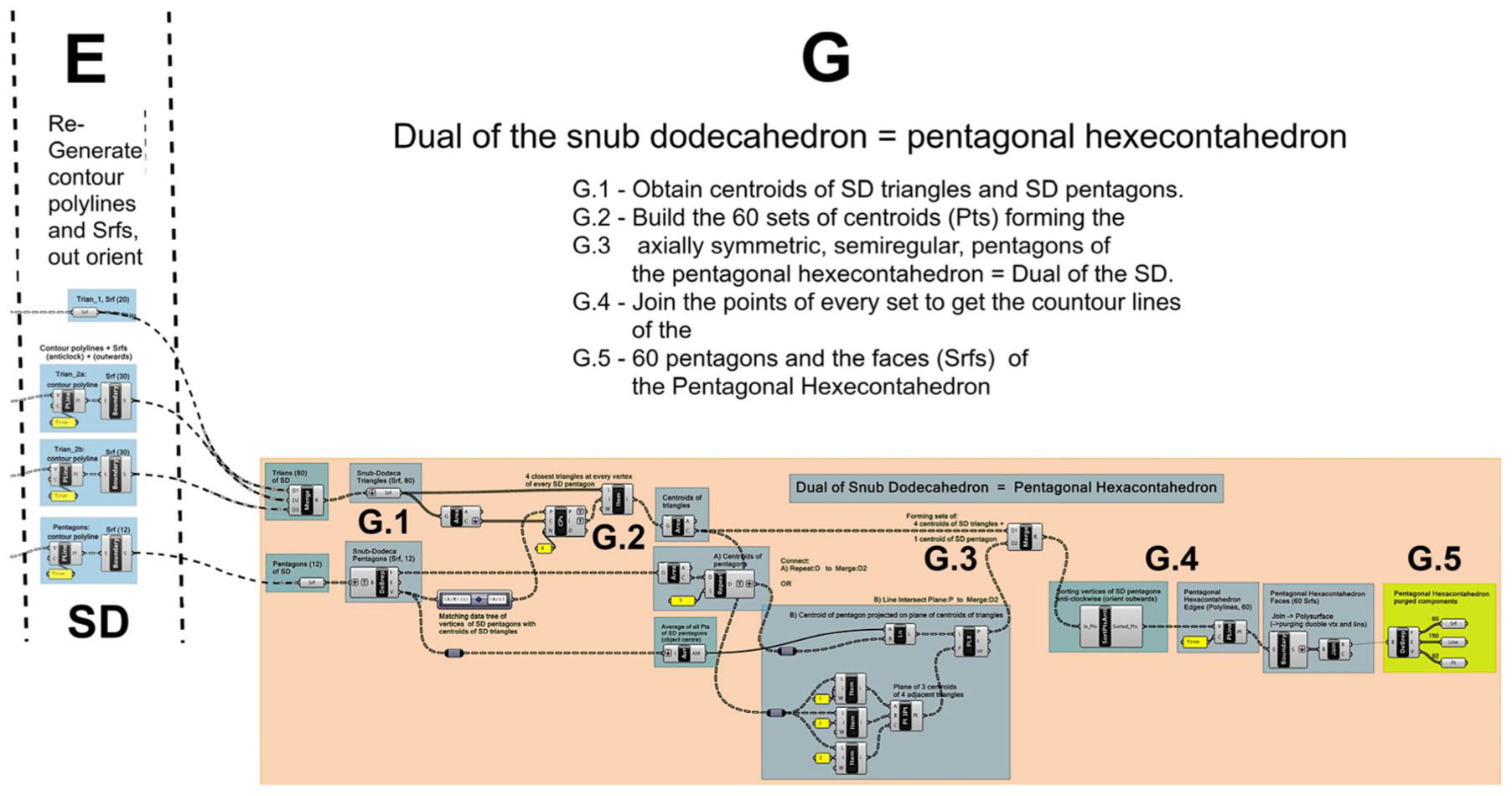
G: Grasshopper script for the SD-Dual, the pentagonal hexecontahedron (left form). Overall view.
E-G.1–G.2: The centroids of SD triangles and pentagons
Figure 11: E-G.1. The faces (Srfs) coming from the GH-script section E are combined in two sets. The first set contains the surfaces Trian_1, Trian_2a, and Trian_2b, that is, all 80 SD triangular faces (Srfs) “flattened” in one list, and the second set contains the 12 SD pentagonal faces.
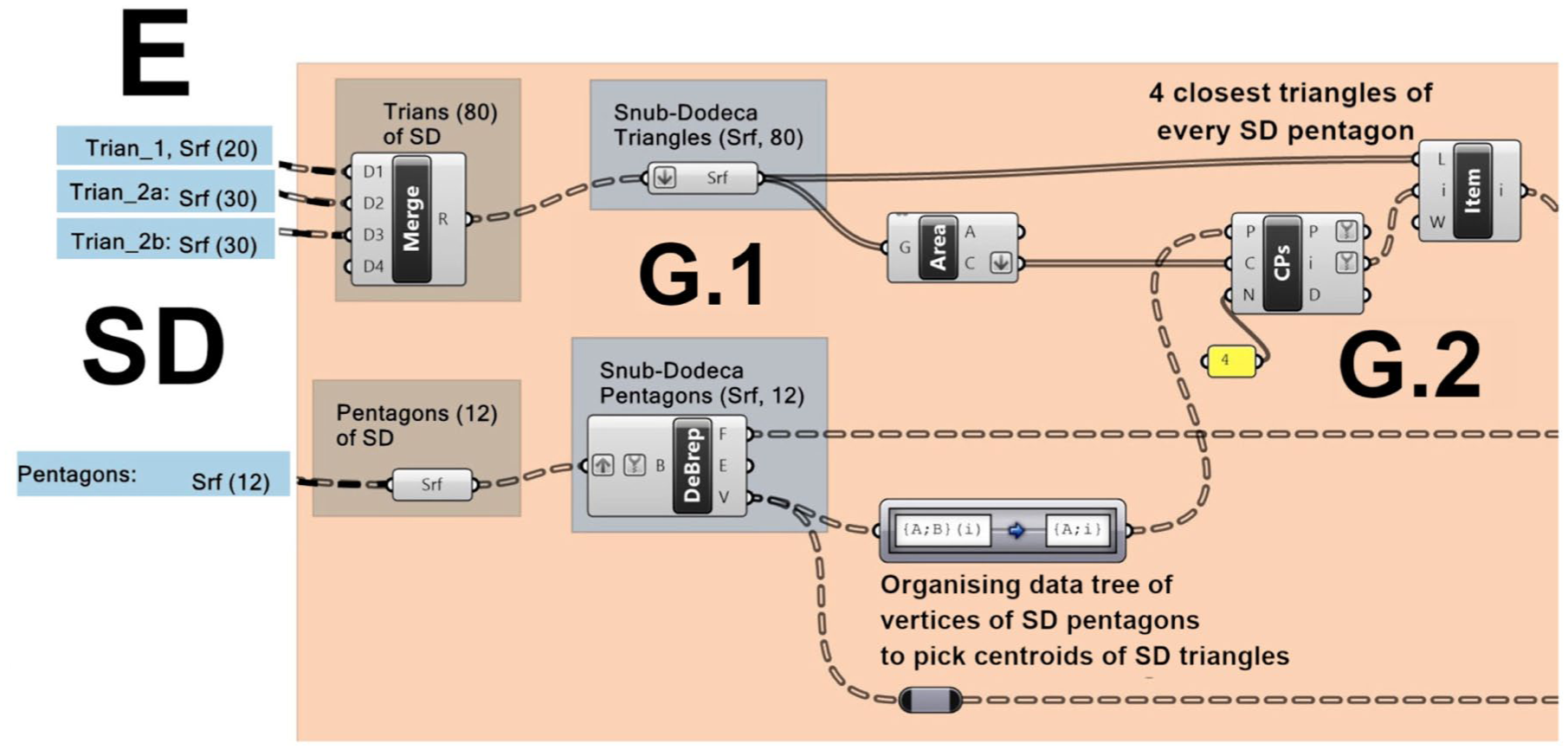
Finding the four centroids of SD triangles at every vertex of SD pentagons.
The 12 SD pentagonal surfaces are deconstructed in faces, edges, and vertices. The vertices are consequently organized in 12 data branches with 5 points per branch. With the aid of the Path-Mapper-component every vertex of a pentagonal face is displaced deeper into a further branch, so that every vertex can be addressed individually.
Figure 11: G.2. It is important to note that in the snub dodecahedron, four triangles meet at every vertex of every pentagon. Thus, the Closest-Points-component is used to find the indices of the four closest centroids at every pentagon’s vertex of the overall collection of 80 triangles. These indices are passed on to the List-Item-component to select the corresponding four triangles at every pentagon’s vertex.
G.2–G.3: The sets of five vertices of the isosceles pentagons of the pentagonal hexecontahedron PH
Figure 12: G.2. After the four closest centroids of the SD triangles at every SD pentagon’s vertex have been specified, the centroid of the closest SD pentagon is added to the current set of four centroids to define the five vertices of the typical isosceles pentagon of a pentagonal hexecontahedron. It should be noted that the SD pentagon’s centroid does not lie on the plane defined by the four SD triangles’ centroids. To later get a planar PH isosceles pentagon, the centroid of the SD pentagon is centrally projected to the plane of the four SD triangles’ centroids from the center of the SD, as shown in Figure 12-G.3. Here, the Merge-component builds the 60 sets of 5 points defining the vertices of the 60 PH isosceles pentagons. In this configuration, the centroids of the four SD triangles have a common circumscribing sphere, while the projected centroids of the SD pentagons have another, slightly larger, circumscribing sphere.
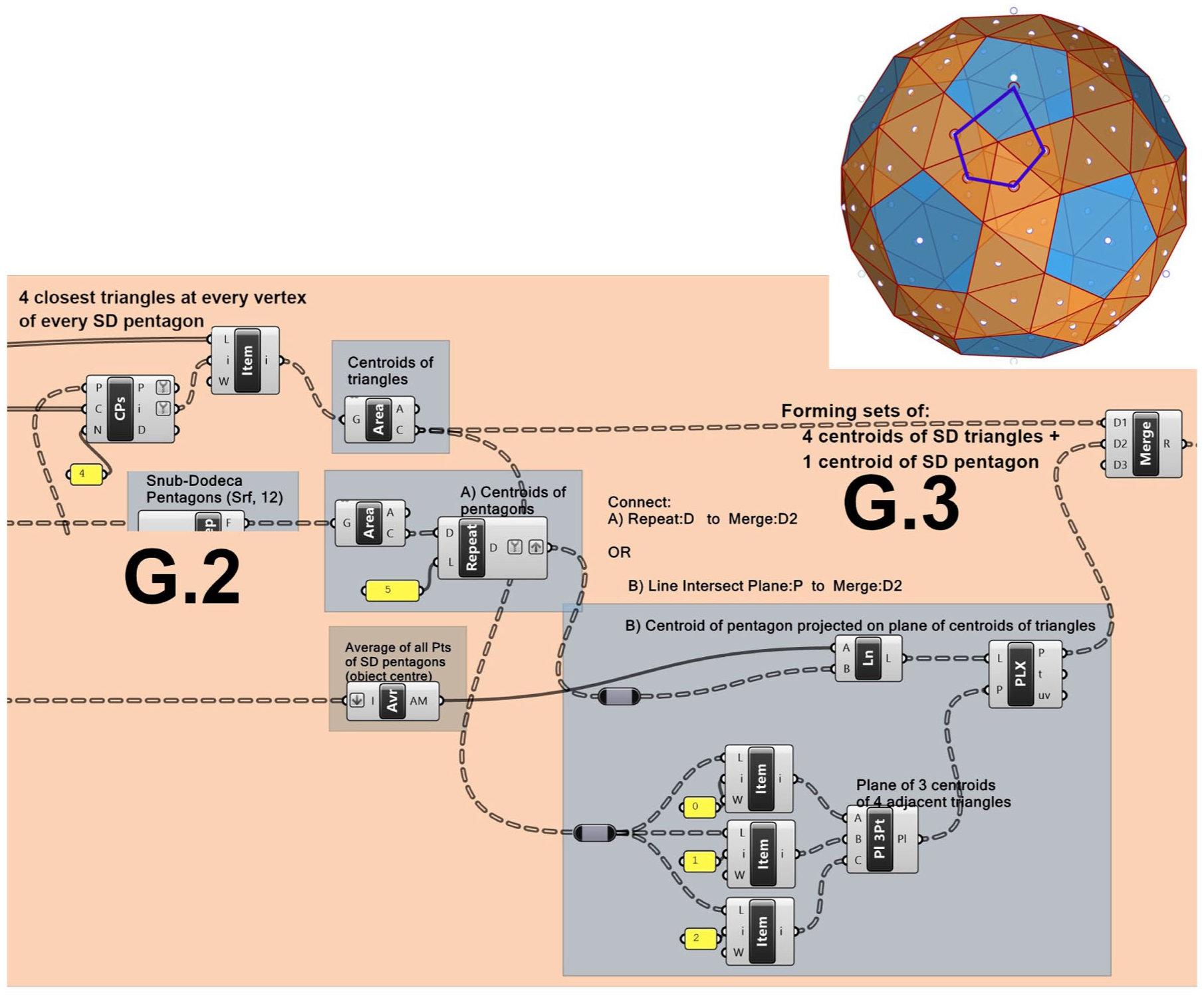
Generating the sets of five points defining the vertices of the isosceles pentagons of the pentagonal hexecontahedron.
G.3–G.5: Composing the pentagonal hexecontahedron
Figure 13: G.3–G.4. Once the 60 sets of PH vertices have been defined, the vertices in every set are ordered anticlockwise and hence outwards. The Closed-Polyline-component generates the 60 coplanar linear boundaries of the PH faces. The Boundary-component creates in turn the 60 planar faces of the pentagonal hexecontahedron (here in a left form). The following Join-component welds these faces into a polysurface, which is in turn deconstructed with the DeBrep-component.
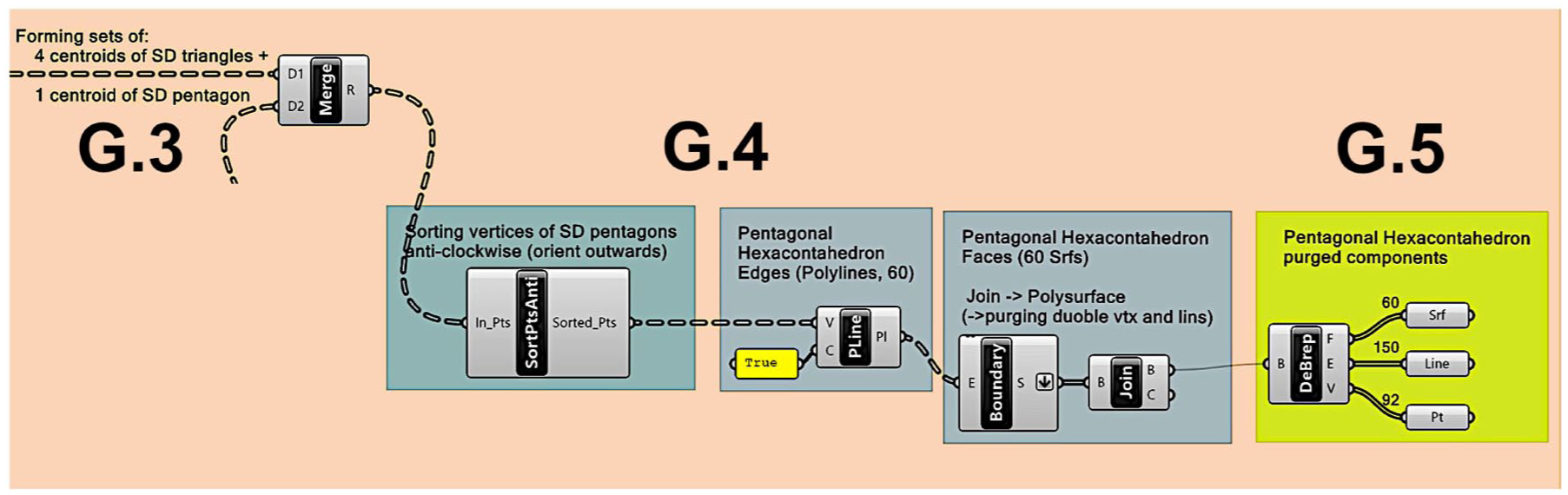
PH component objects: ordered vertices of faces, polyline boundaries and pentagonal faces (Srfs).
Figure 13: G.5. The Join/DeBrep combination takes care of eliminating redundant points and lines and yields the final individual geometric components of the Pentagonal hexecontahedron PH, namely, 60 identical isosceles-pentagonal faces (Srfs), 90 “short” and 60 “long” edge lines, and 92 individual vertices (Pts).
The result of the duality procedure is shown in the two images of Figure 14, left, with the line network of the snub dodecahedron SD, in red, combined concentrically with the pentagonal hexecontahedron PH, in violet, thereby illustrating the duality relationship between the two polyhedra. The image on the right of Figure 14 displays the PH on its own. Finally, a study on a tubular structure based on the pentagonal hexecontahedron is shown in Figure 15 to conclude the GH-formulation exercise.
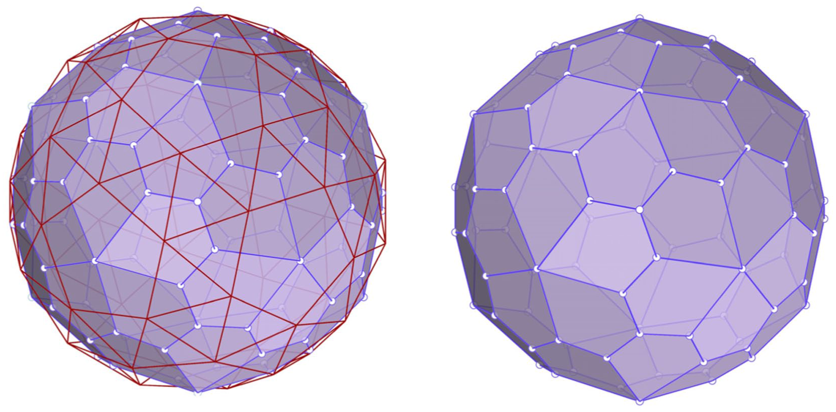
The snub dodecahedron (red lines) and its dual, the pentagonal hexecontahedron (violet).
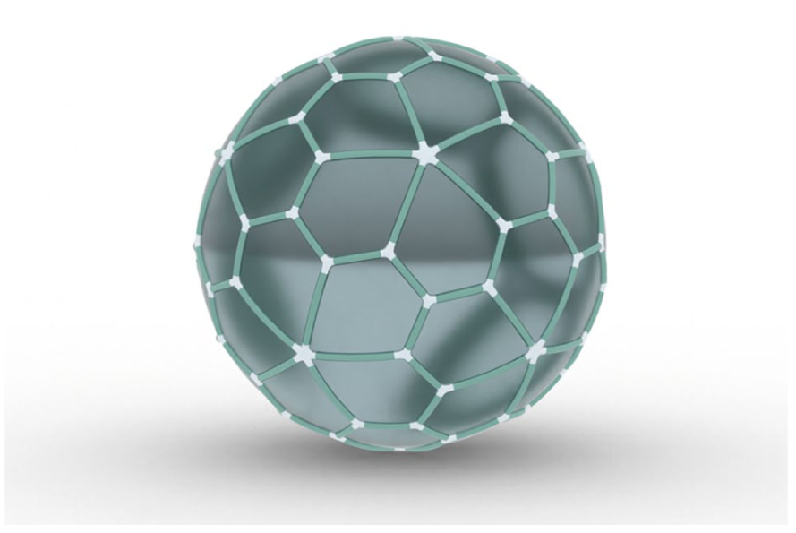
Study on a tubular structure based on the pentagonal hexecontahedron.
Conclusion
The Grasshopper formulation for the snub dodecahedron and the pentagonal hexecontahedron has been an exercise in expressing a geometric construction method, a structured modeling strategy or algorithm, and the related data handling of complex geometric objects, in terms of the language elements and functions of the user-programming platform Grasshopper, which is an extension of the geometry program Rhinoceros 7/8. The user-friendliness and efficiency of Grasshopper have allowed the formulation of the given tasks in a readable, compact, and elegant manner. However, more than the translation of the geometric construction task and its related data handling in terms of the language elements and functions of Grasshopper, the fundamental aspect of the GH-formulation has been the clear specification of the geometric construction method, the layout of a structured modeling strategy or algorithm, and an as-simple-as-possible but efficient data organization.
The Grasshopper script(s) in this paper can be used in several ways, for example, as a learning material to follow step by step the GH formulation, its generation strategy and logic, and its implementation through GH components. Moreover, understanding and exploiting the possibilities of the GH data-tree structure is essential for efficient data handling, which typically leads to a significant reduction in script size and improved computing performance. In a practical design context, the scripts in this paper can be incorporated into the workflow of an engineering, architectural, construction, or fabrication process, either as a stand-alone application or within another, larger Grasshopper script, provided the input icosahedron is present in the Rhino modeling space. Moreover, a user may wish to extend the provided script with an initial script piece that generates the input polyhedron, resulting in a real stand-alone GH-script.
There are also other Rhino add-on packages and Grasshopper plug-ins that can generate models of the polyhedra discussed here, as well as many other objects used in architecture, structural engineering, product design, and 3D art. The aim of this discussion, however, is partly to warn against the uncritical use of “black boxes,” in which the user inputs a few parameters and receives a “desired” result without understanding what happens inside the box. Designers should choose the approach that best fits their purpose, if possible, in a conscious manner. At a deeper level, the idea is to maintain control over the available tools, rather than allowing them to steer the design along a biased or predetermined path. The designer should define the path and adapt the tools to the design requirements and the final objective.
The programming platform provides the tools, while the human mind remains the creative agent.
Footnotes
Author’s note
The author will share the Grasshopper scripts from the article with readers who request them by email.
Authorship originality
The text, the programming scripts, and the illustrations (except for the photo included in ![]() ) in the article are original material produced by the author. The article is submitted for the first time for publication in the International Journal of Space Structures; that is, it has not been published elsewhere.
) in the article are original material produced by the author. The article is submitted for the first time for publication in the International Journal of Space Structures; that is, it has not been published elsewhere.
Declaration of conflicting interests
The author declared the following potential conflicts of interest with respect to the research, authorship, and/or publication of this article: The author declares no potential conflicts of interest with respect to the research, authorship, and/or publication of this article. The contribution contains a photograph from the Internet in ![]() , whose property and usage have been properly acknowledged as required by the owner of the material by reference citations and/or with credits in the captions of the photo. Otherwise, all images in the contribution have been solely created by the author of this paper. Moreover, the text, the programming scripts, and the illustrations (except for the photo included in Figure 1) in the article are original material produced by the author.
, whose property and usage have been properly acknowledged as required by the owner of the material by reference citations and/or with credits in the captions of the photo. Otherwise, all images in the contribution have been solely created by the author of this paper. Moreover, the text, the programming scripts, and the illustrations (except for the photo included in Figure 1) in the article are original material produced by the author.
Funding
The author disclosed receipt of the following financial support for the research, authorship, and/or publication of this article: Writing the text and producing the graphic material in the contribution have not been supported by any funding. The article was exclusively produced as the private work of a single author.