
Abstract
For the foreseeable future, tall building structures will be built taller and more flexible, which means more vulnerable to excitations. As such, there is considerable interest in developing structural control methods to protect against harmful vibrations. However, challenges present themselves for conventional mass damper systems as these tend to primarily utilise lateral motion which becomes very limited as the height of structures increases. This article proposes a novel approach to reduce tall building’s long-period oscillations using mass damper motion in the much larger longitudinal direction. This motion induces Coriolis effect and if manoeuvred properly can be used to effectively reduce vibration of the primary structure. Numerical analysis was done using finite element method. The Shinjuku Mitsui Building was used as a benchmark for the primary structure, which was modelled as a vertical cantilever beam. The results showed the concept to be a viable approach for damping long-period vibrations of flexible structures. Enhancing this effect was also introduced and briefly discussed, using a multiple-degree-of-freedom damper and a constant positive velocity water-flow damper as examples. Further work continues for optimum design of the concept to make it a practical approach for tall buildings. Additionally, investigation into enhancing the damping effect is being done in more detail. This approach provides new possibilities for vibration control of any long-period structure.
Keywords
Introduction
Tall structural systems are susceptible to vibrations when subjected to excitations. These vibrations are hazardous to the structures, unpleasant for occupants and may even pose serious serviceability issues. 1 This has been and remains a great concern for researchers.
The direction of evolution of tall structures is towards lightness 2 and is often featured with increased flexibility and a lack of sufficient inherent damping making them more vulnerable to excitation. 1 Additionally, urbanisation and population increase create the need to maximise space, forcing mankind to continue building upwards. This trend is not likely to be reversed in the future, and as such we will more likely see a significant amount of tall or super tall structures, in particular in metropolitan areas. To reduce vibrations in these structures, auxiliary damping measures, commonly mass dampers, are implemented. Conventional systems make use of the lateral space, and as structures become taller and thinner, conventional systems may not have adequate space for effective motion.
An alternative approach could be to use the longitudinal space which is significantly greater. When these structures vibrate, they undergo a certain amount of rotational motion. As such, any motion in the longitudinal direction will induce Coriolis effect which may be used to attenuate these structures. This was investigated in Matsuhisa et al. 3 and Viet et al. 4 for pendulum systems. They investigated a system where a mass moves in the radius direction and induces Coriolis force in the circumference direction to prevent the swing of gondola. This concept is similar to a child’s up–down motion to pump a swing.5,6 In this case, the child alternates the up–down motion to amplify the swing, and maximisation of this depends on the timing of the motion. 7 Using this concept to control the sway of a crane was studied in Viet. 8
In principle, this could be applied to tall structures. These structures could be simply modelled as a vertical cantilever beam with its base fixed in the ground, 2 and the dynamic response due to the moving load could be investigated.
There are many works presented on the analysis of the dynamic response of structures under the influence of moving mass. Many works such as by Fryba, 9 Oguamanam et al. 10 and Olsson 11 found approximate analytical solutions to the problem by considering the moving load as a moving force. However, in these, the inertial mass and/or the Coriolis and centripetal effect from the interaction of the mass and the beam are neglected. Further works have shown a more complete analysis by considering the moving load as a moving mass and shows the importance in particular for large masses, high velocities and substantial deflection.12 –14 The numerical approach of finite element method (FEM) has garnered much attention due to its flexibility and ease by which the mass effects may be taken into account. In Ye and Chen 15 and Wu, 16 the authors investigated the dynamic response using moving FEM. The aforementioned investigations, however, focus on the effect of the moving load on an initial stationary structure. Also, the mass traverses once, usually with a constant velocity, over the structure. To the best of the author’s knowledge, few investigations have gone into using the effects of an accelerated moving mass to attenuate the vibration of tall flexible structure via cyclic motion.
This article investigates the damping effect of a moving mass on a long-period vibrating vertical cantilever beam. The dynamic response is investigated by modelling the mass as a moving finite element to easily take into account the inertial, centrifugal and Coriolis effects of the moving mass on the structure. The concept of enhancing the effect is also briefly discussed using a multiple-degree-of-freedom damper and a constant positive velocity water-flow damping system as examples. The problem presented should be considered as a first investigation into developing a strategy for active control of structural vibrations using the longitudinal motion of a moving load. This is especially attractive for cases where there is low structural damping and thin structures where lateral space is insufficient for adequate damping motion.
Formulation of the problem
In this section, the equations of motion of the system are given.
Equations of motion through Hamilton’s principle
The equations of motion of the system can be analytically derived using the extended Hamilton’s principle. The model of the concept is shown in Figure 1. The vibrating primary structure is modelled as an Euler–Bernoulli beam with its bottom end fixed in the ground. The moving mass m moves over the structure and is able to move up and down. The horizontal deflection of the beam is given as

Vibrating vertical cantilever beam with a moving mass on it.
The energy of the system presented is due to (1) the beam and (2) the moving mass.
The kinetic energy of the beam
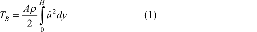
where
The kinetic energy of the mass

where
The total kinetic energy of the system

The potential energy of the system

where
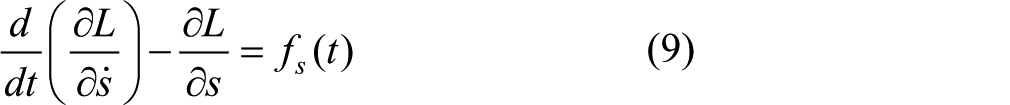
Now for the Lagrangian mechanics which states

Using Hamilton’s principle
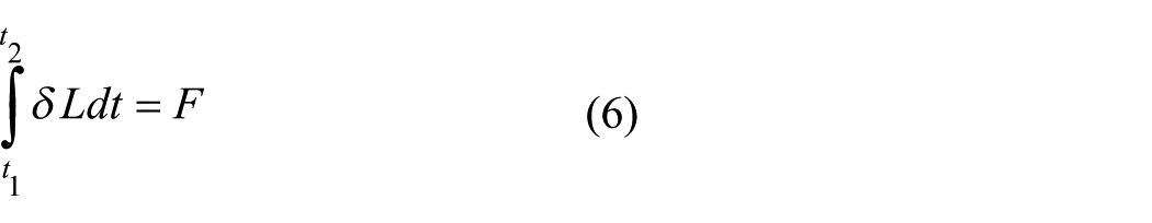
where
Considering the beam structure and using equation (5) in equation (6), we get
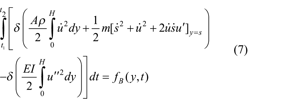
where
Using integration by parts, equation (7) becomes
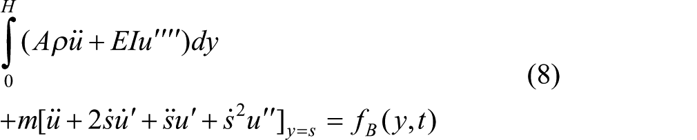
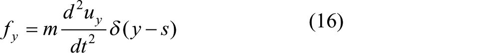
In the case of free response where the only force applied to the beam would be due to the motion of the moving mass,
To find the equation of motion of the moving mass, we consider the
where

Motion of moving mass
In equation (8), the
Further examination of the Coriolis effect also reveals that for maximum effect, the velocity of the moving mass should be maximum at the moment the primary structure has maximum angular velocity. From this, we prescribe the motion of the moving mass to be

where

FEM
In this section, the finite element approach is illustrated.
Figure 2 shows the finite element model of the system. The beam of height

FEM model of vertical cantilever beam with moving mass.
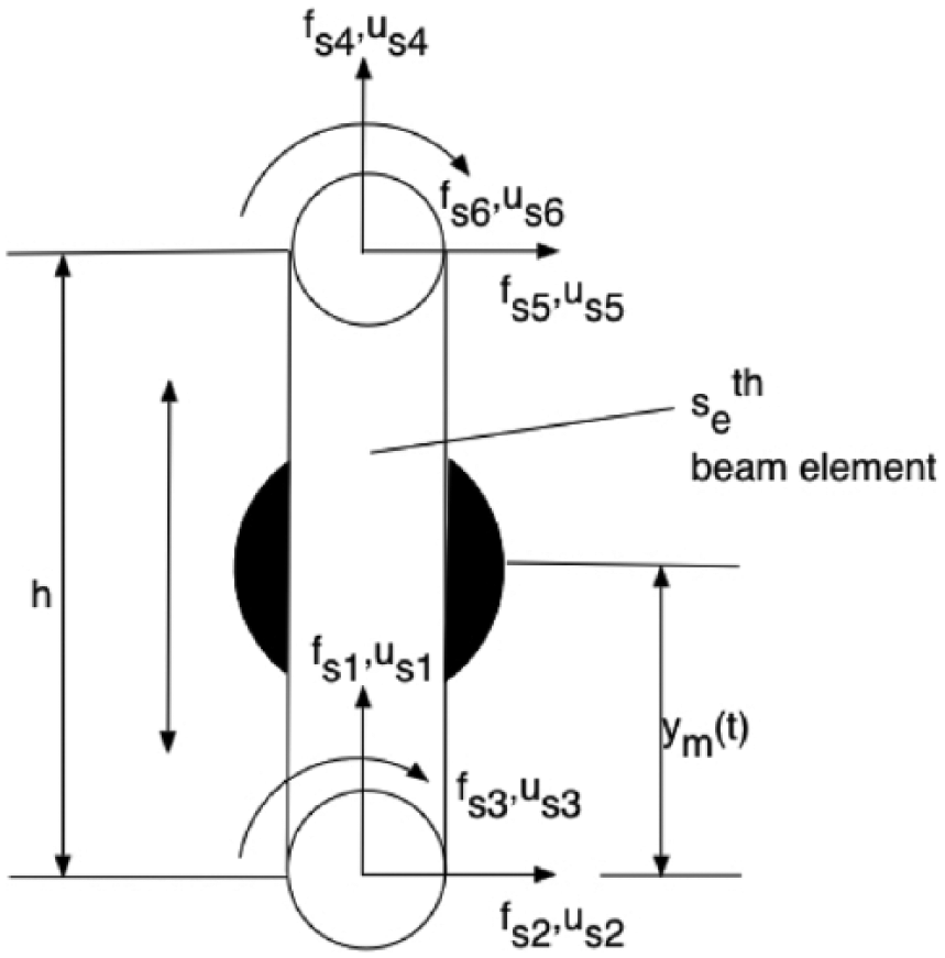
Beam element on which moving mass is located.
The primary structure
Using FEM, the primary structure is modelled as

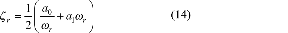
The damping factors are given by
Moving finite element
In this article, the moving FEM is used to easily take into consideration all the internal forces acting on the system due to the interaction of the vibrating beam and the moving mass. These include the inertial forces, centripetal forces and the most important the Coriolis effect. These forces are described below.
Nodal forces of moving finite element
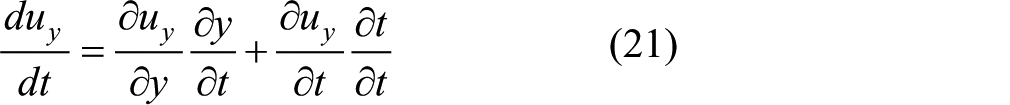
The vibration and curvature of the beam induce forces due to the interaction between the beam and the moving mass. From this point, we represent the parameters of
Transverse
Longitudinal
where
For transverse direction

which gives

And

which gives
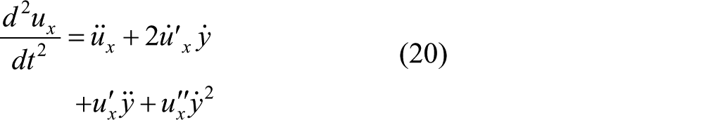
For longitudinal direction
which gives

Assuming the beam is inextensible, the first term can be ignored and equation (22) can be approximated as

And
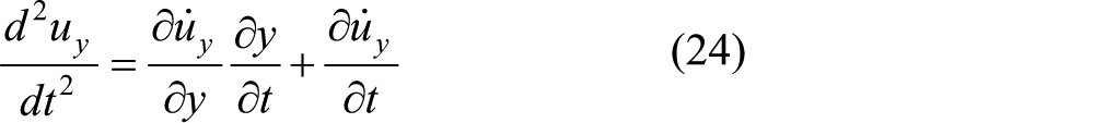
which gives
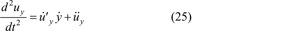
Again using the assumptions above, we can approximate equation (25) as

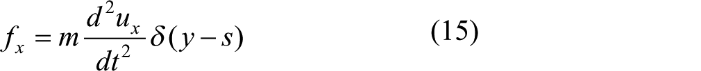
Substituting equation (20) into equation (15) and equation (26) into equation (16), we get

Since


From this, we can get the equivalent nodal forces

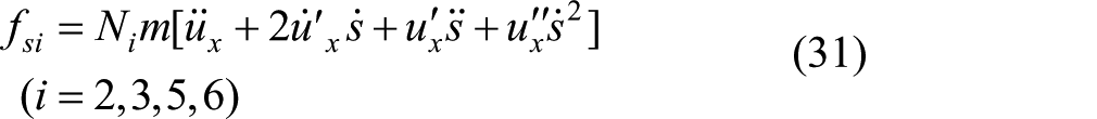
where
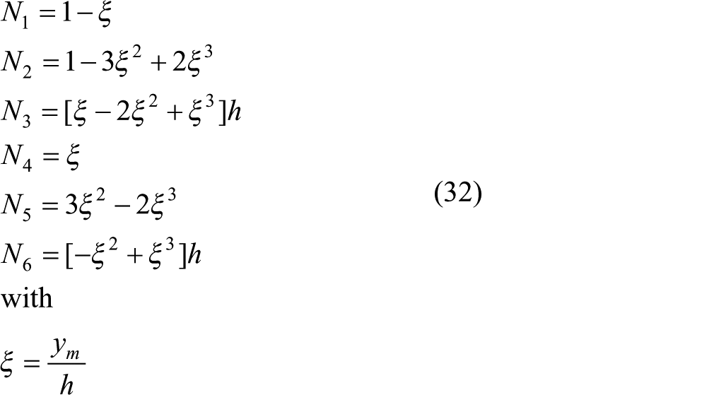
where as shown in Figure 3
We can now show the longitudinal
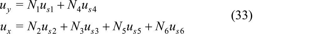
where
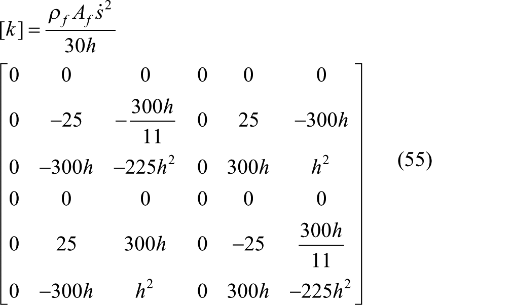
Substituting equation (33) into equations (30) and (31) and writing in matrix form yields equation

where
where
Entire structural system
Equation of motion
The equation of motion of the entire structural system is governed by

where
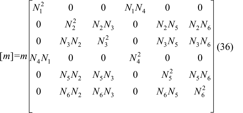
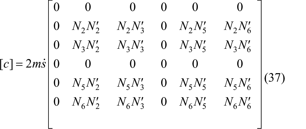
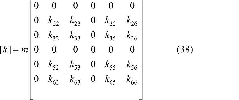
Mass, stiffness and damping matrices
The mass, stiffness and damping matrices are obtained by assembling the element matrices and imposing boundary conditions. For this, we take into consideration the element matrices of the moving finite element. As such


except for the


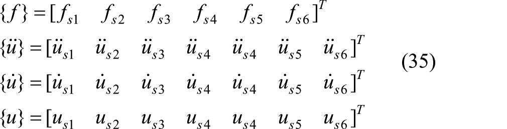
Overall force vector
The overall force is due only to the forces in the
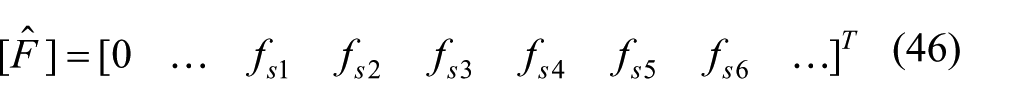
where the nodal forces are found using equations (30) and (31).
Solution of equation of motion
The solution to the equation of motion can be obtained by numerical integration. There are several methods that exist, but for the purpose of this article, we use Newmark’s method as illustrated in Rajasekaran. 19
Results and discussion
Numerical example
In the 2011 Great East Japan Earthquake, tall buildings in Tokyo were oscillating even 30 min after. One such building was the Shinjuku Mitsui Building which, according to reports, had deflection at the top of almost 2 m.
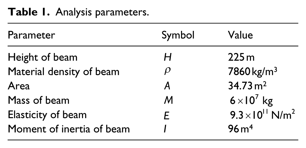
As an example consider the Shinjuku Mitsui Building modelled as a vertical cantilever beam fixed at the base. The properties of the beam are listed in Table 1. Most mass damper systems in structures are designed to be within a mass ratio (µ) range of 1%–10%, so this will be used as the benchmark.
Analysis parameters.
The dimensionless stroke length

The parameters for the proposed damping system are chosen as
Case 1: prescribed motion of moving mass
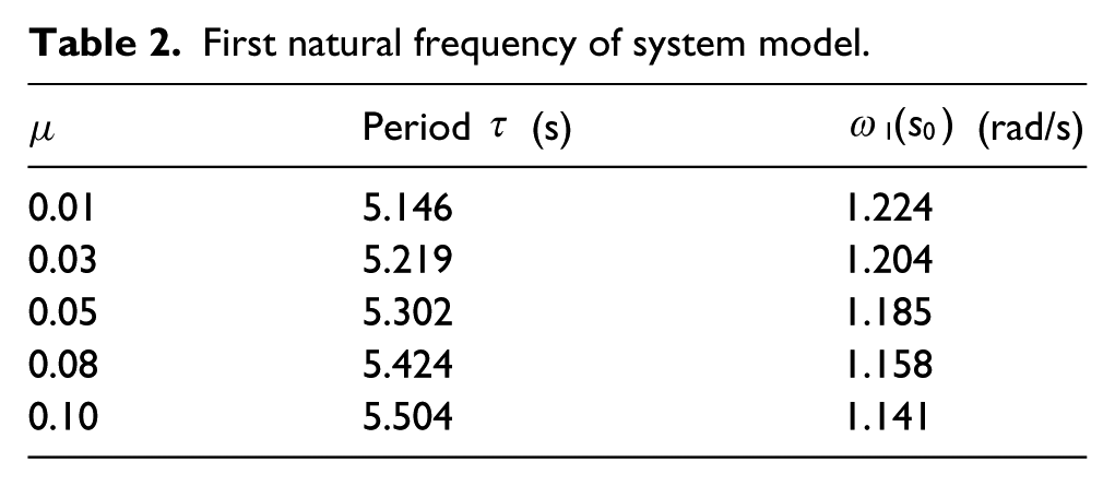
The motion of the mass is prescribed as such given in equation (11). For this, we first calculated
First natural frequency of system model.
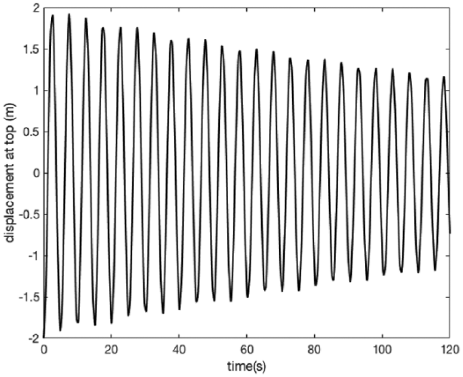
For all the cases, the primary structure is given an initial displacement
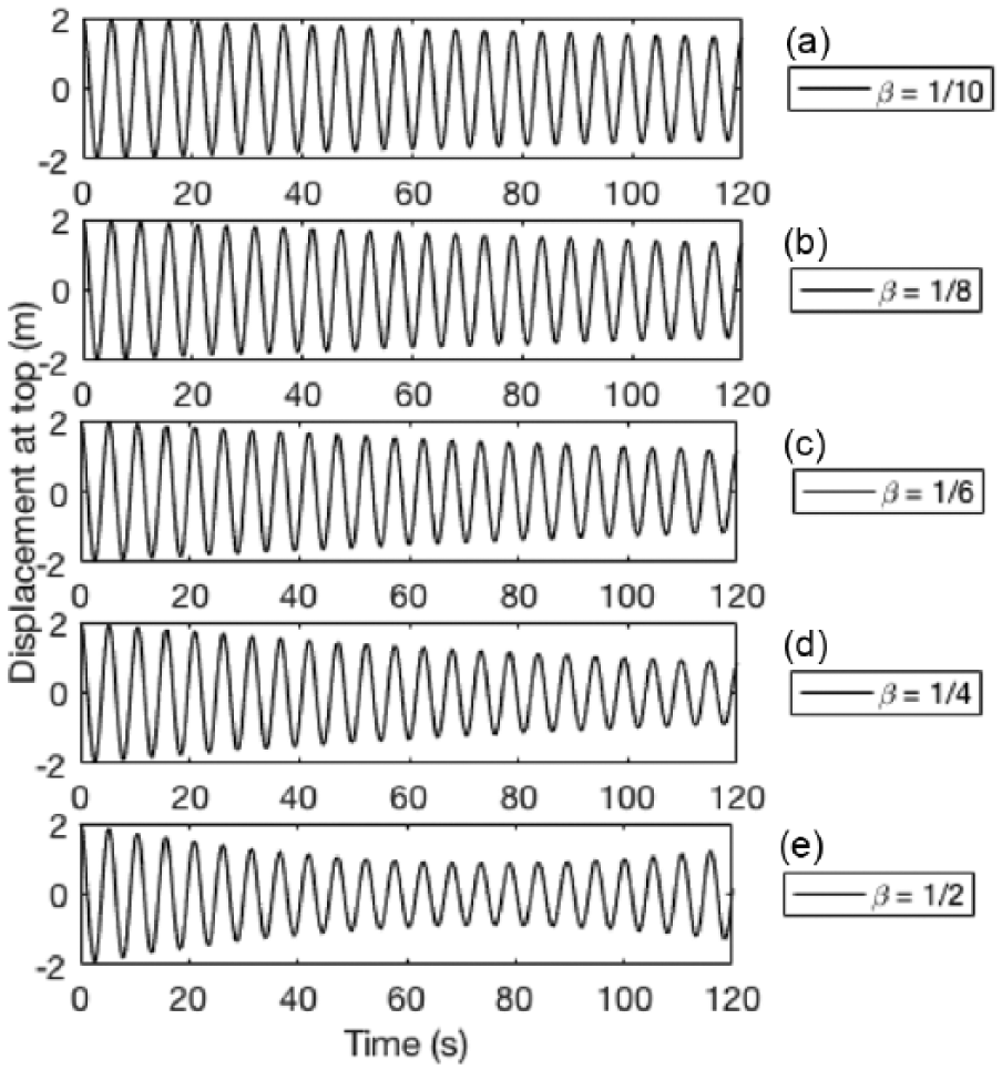
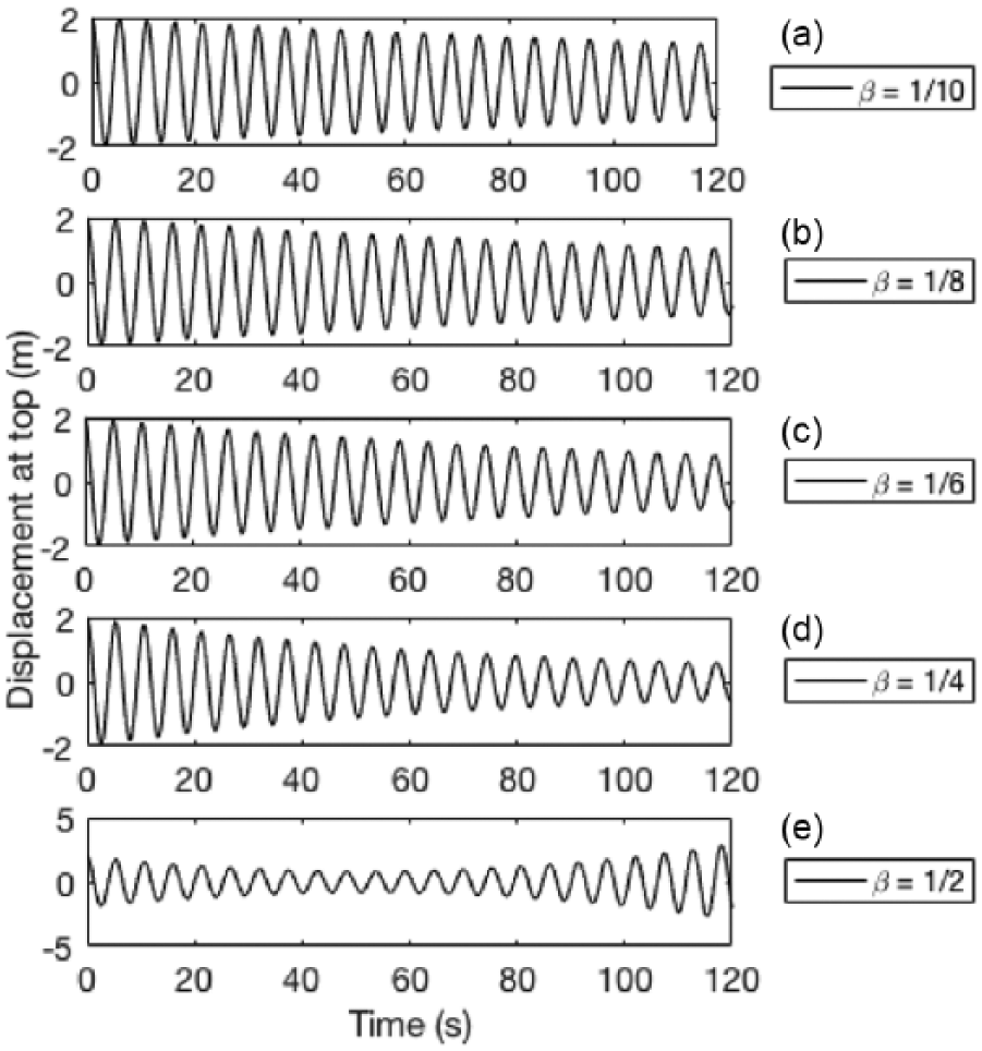
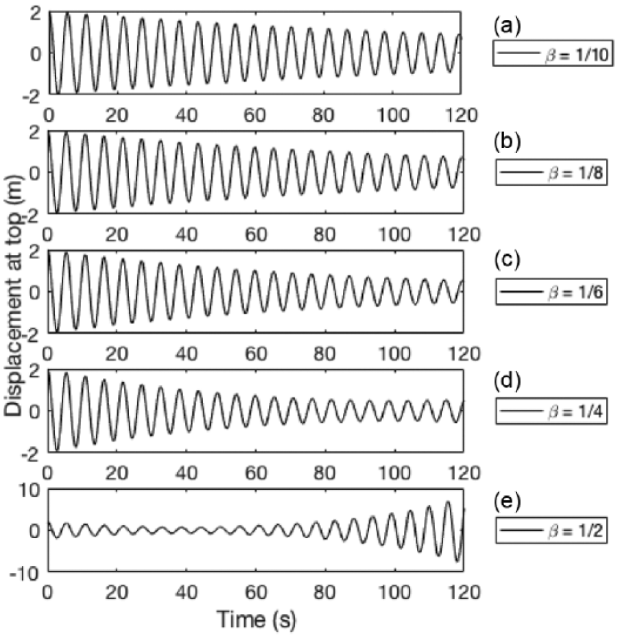
Numerical analysis is carried out using FEM where the beam was discretised into 225 identical elements. The inherent damping of the primary structure was chosen to be 0 to clearly illustrate the damping effect due the damping system. Equation (39) is numerically integrated using Newmark method. The dynamic responses at the top of the structure subjected to a moving mass are shown in Figures 4 –8.
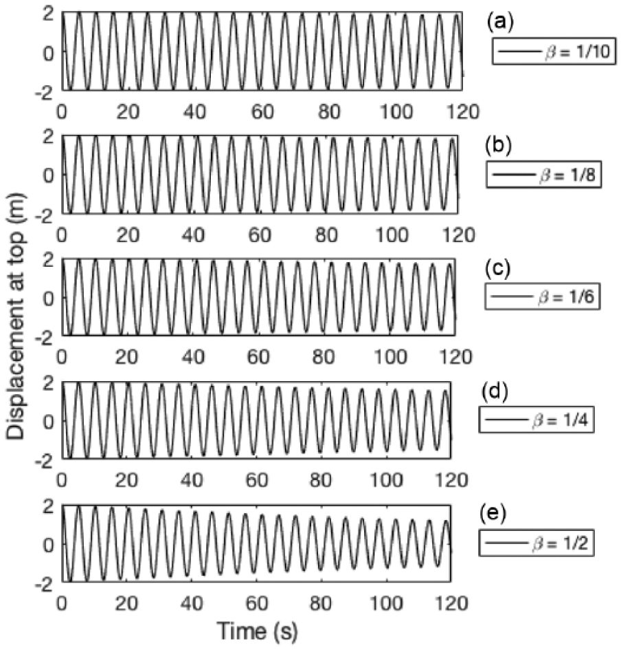
Dynamic response at the top for
Dynamic response at the top for
Dynamic response at the top for
Dynamic response at the top for
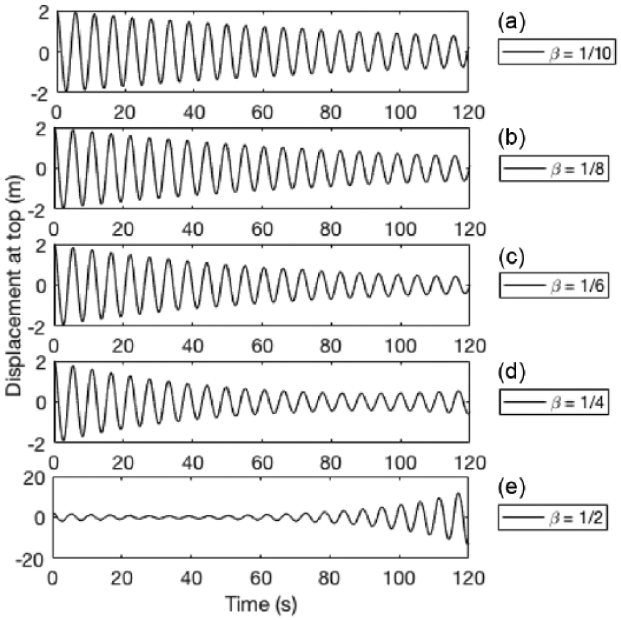
Dynamic response at the top for
From these, we can see that there was no visible damping effect for the case of the small mass
Additionally, for the cases of the larger mass ratios and longer stroke lengths, the results show that at some point the system experiences no damping effect and instead began amplifying the primary structure. This is as a result of the fixed motion of the moving mass along the structure causing a phase shift in each cycle. For example, the dynamic response of the system for one cycle and the motion of the damping system are shown in Figure 9, for the case of

Dynamic response of structure and motion of mass for
Case 2: synchronised mass motion
As mentioned above, a continuous fixed motion of the moving mass will lead to a phase shift in the system which then makes the damping system no longer effective after some point. As such, it is vital for the moving mass to be monitored and constantly adjusted so as to ensure continuous damping of the structure. For this to happen, the phase shift between the moving mass and the response of the primary structure will need to be as close as possible to 0 and should never exceed π
A simple preliminary feedback control system is presented below. Since the phase shift at the end of one cycle is not so significant, to save on monitoring and readjusting time, the feedback system can monitor the position of the moving mass and readjust at the end of each cycle (such as for this case presented we readjust when displacement of primary structure is positive and velocity is 0). If at the end of the cycle depending on whether the motion of moving mass is ahead or behind the motion of the primary structure, the velocity of the moving mass is then adjusted in order to minimise the phase shift. The result for the case of

Dynamic response of structure with synchronised motion of damping system for µ
This feedback and readjustment method is quite effective and produces consistent damping effect throughout the extended time period. The damping ratio

where
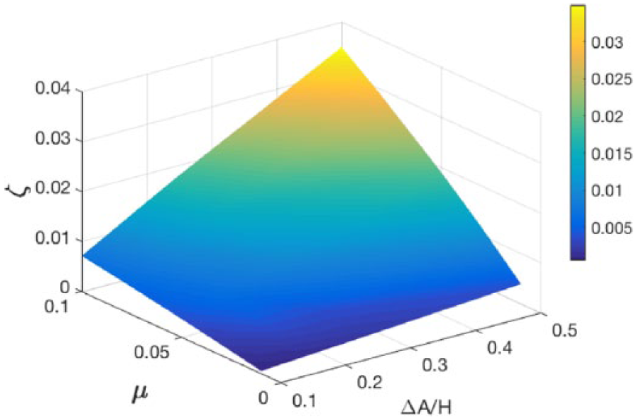
Effects of dimensionless stroke length
From the results, the concept is capable of producing substantial damping effect, in particular for the cases of larger mass ratios and longer stroke lengths.
Practical implications
The concept presented in this article is an idea to attenuate long-period oscillation of building structures, in particular in the event of large excitation, to reduce the response to an acceptable degree. This theory of damping measure is quite attractive; however, at present technical limitations prevent this measure from being a practical concept for damping tall building structures. In particular, the speed required for the moving mass is of concern. The peak speed of the moving mass as it relates to the dimensionless stroke length
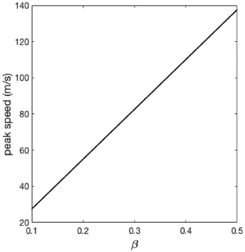
The peak speed of moving mass for each dimensionless stroke length
However, the concept as such is quite feasible for long, thin and flexible structural systems such as beams and frames. Especially if the motion of the structure is dominated by the lowest mode of vibration.
It is worth mentioning that the Coriolis effect generated by the moving mass can be enhanced. As mentioned in section ‘Motion of moving mass’, there are several parameters that influence the Coriolis effect, one of which is the degree of angular motion. As such, we can enhance the effect as illustrated in Figure 13. The damping system has multiple degrees of freedom with a moving mass translating along an axis with angular motion. The angular motion of the pendulum and the up–down motion of the mass are carefully synchronised with the motion of the primary structure to maximise damping effect.

Illustration of the concept of a multiple-degree-of-freedom enhanced Coriolis effect damper.
One way to realise this is to have a driver located at the top of the structure moving laterally facilitating angular motion of the oscillating fixture about its pivot, while the moving mass translates along it (see Figure 14). It should be noted that this driver can be actively or passively driven. Additionally, the inertial properties of the driving mechanism and the oscillating fixture can add to the attenuating effect of the moving mass, much like a tuned mass damper (TMD).

Example mechanism of a multiple-degree-of-freedom enhanced Coriolis effect damper.
Another parameter that influences the Coriolis effect is the velocity of moving mass. Careful examination of the Coriolis component of equation (8) reveals that a positive velocity yields positive damping effect and a negative velocity yields negative damping effect. Since the motion of the moving mass is cyclic, this means in one cycle the system goes through alternating phase of damping and attenuation, but with careful manoeuvring the period of damping is greater at the end of the cycle. However, if the velocity were to remain positive throughout the whole cycle, this would increase the overall damping effect. We show this by the primary structure having a pipe through it which allows the flow of fluid. For this case, we use water flow (see Figure 15). The basic idea is to attenuate the long-period vibration of the primary structure using high-speed water flow in the positive (up) direction.
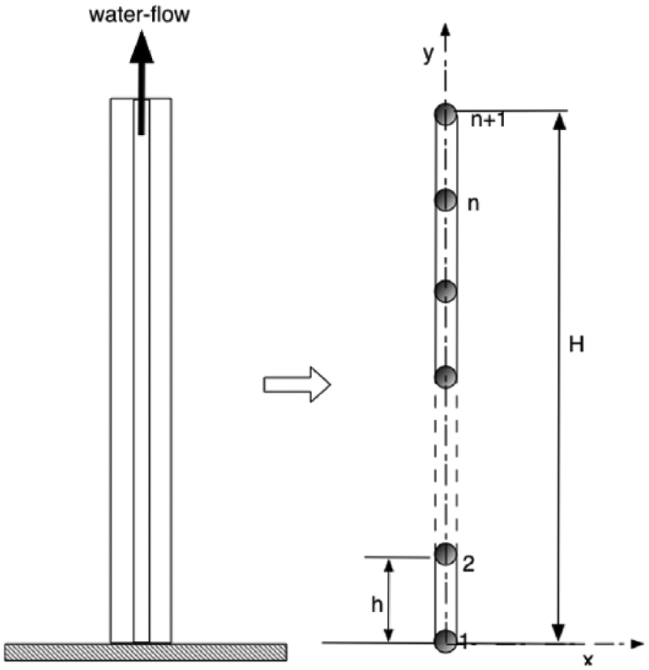
Simplified model of structure with water flow through it and the finite element modelling.
The previous moving finite element model is slightly altered to take into consideration the water-flow effect. The water is pumped upwards with a constant velocity. As such, equation (8) becomes
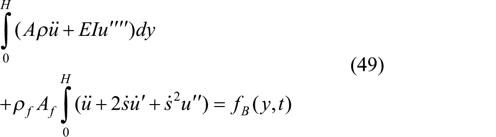
and equations (36)–(38) become
For this case,
We integrate these over the height of the primary structure to get for each element

The result for water flow with mass ratio 1% of the primary structure pumped at velocity 50 m/s is shown in Figure 16. The result shows a similar performance to that of moving mass with
Dynamic response using water flow (
Conclusion
This article proposed a new concept to control low-frequency vibration in tall and thin structures using mass motion in the longitudinal direction. Unlike conventional concepts, the motion of the mass induces Coriolis force and with the appropriate motion reduces the vibration of the primary structure. The system was modelled using FEM, and the dynamic response of the system was analysed. The analysis shows that the concept produces substantial damping effect, and this effect increases with increases in the mass and degree of motion of the moving mass. Furthermore, in order to effectively attenuate the structure for an extended period of time, the motion of the moving mass needs to be constantly monitored and adjusted so as to keep the phase shift in the system to a minimum. The Coriolis effect can also be enhanced by increasing the degree of angular motion of the moving mass or by it having always-positive velocity. This idea of enhancing the damping effect was introduced and briefly discussed using multiple-degree-of-freedom Coriolis damper (angular motion and translation of moving mass) and also using a constant positive velocity fluid flow as examples.
This concept of using Coriolis effect to attenuate structures can be applied to any long-period structure that has rotational component where Coriolis effect can be induced. The proposed concept as presented should be considered as a first step to develop an alternative method for control of vibration in flexible structures in the event of large excitations. This concept is particularly attractive for structures with low inherent damping and limited lateral space and can be applied to a wide variety of structures which include flexible-type, pendulum-type and rolling-type structures.
Future works will in detail look into enhancing damping effect and will investigate the consideration of other modes of vibration.
Footnotes
Appendix 1
Declaration of conflicting interests
The author(s) declared no potential conflicts of interest with respect to the research, authorship and/or publication of this article.
Funding
The author(s) received no financial support for the research, authorship and/or publication of this article.