




Abstract
The high-speed rotors are usually supported on fluid-film bearings such as single film hydrodynamic bearings and floating ring type bearings to attain high damping capacity for minimizing the resonant vibration amplitudes. However, the bearing forces are highly nonlinear and are often prone to stability issues in the system. This work presents the use of an electrorheological fluid as a lubricant in floating ring bearings for rotor vibration control. The unbalance response of the rotor system is obtained from finite element approach by accounting gyroscopic effects and nonlinear bearing forces. By idealizing the electrorheological lubricant using Bingham model, the effective Reynolds equations for inner and outer films are formulated in terms of film pressures and thickness values. The coupled differential equations are solved numerically and the effect of external applied electric field on the dynamic response is studied in detail. A case study of automotive turbocharger rotor system is selected for illustration.
Keywords
Introduction
In high-speed rotors like turbochargers, the turbine and compressor wheels are mounted at the two ends and the shaft in turn is supported on hydrodynamic fluid-film bearings. The power generated at the turbine from expanding exhaust gases is just sufficient to drive the compressor at the other end. The compressor pressurizes intake air and sends into the combustion chamber. The life span of such a self-powered turbocharger rotor depends on the bearing supports. A small-unexpected vibration may damage the bearings and reduce the life span of the turbocharger because their operating speed is very high. Due to these reasons, a special attention is required throughout its operating range. Various types of defects form at different components of the system due to repetitive usage. This makes it a high response and violent vibrations at critical speeds of operation. Eventually, noise and rotor–stator rub may occur from large amplitude vibrations, which are undesirable. Minimizing responses and vibration control is the preliminary consideration in the design of such turbomachinery.
Several past studies1–3 proposed the turbocharger rotor stability analysis issues when the rotor is supported on the floating ring bearings. Gjika et al. 4 explained the nonlinear dynamic behavior of the automotive turbocharger with radial bearings of two oil films in series. The model predictions were validated with experimental data and demonstrated by considering the several subsynchronous frequency components on the nonlinear character of the radial bearing system behavior. Tian et al. 5 proposed dynamic behavior of a realistic turbocharger rotor system under the influence of the unbalance and the engine excitations. The nonlinear floating ring bearing forces based on Capone’s method were considered in the study. This study shows that the unbalance had a great effect on rotor response at lower speeds and the engine excitation effects had a distinct difference at lower speeds. Zhang et al. 6 proposed a method to monitor the turbocharger bearing clearance and its variation with the use of oil film pressure. Tian et al.7,8 studied the effect of the unbalance and the floating ring bearing outer clearance on the rotor dynamic characteristics of turbocharger supported over the floating ring bearings during run-up and run-down conditions. Bonello 9 explained a nonlinear dynamic analysis with a computational method for the turbocharger rotor supported over the floating bearings and studied the self-excited vibration of the turbocharger. The analysis was carried out for both fully floating ring and semi-floating ring bearings. Lee et al. 10 illustrated the effect of gas foil bearings on dynamics of turbocharger rotor and compared the results of the rotor with floating ring bearings. Peng et al. 11 suggested a material selection approach for turbocharger floating ring bearings. In a more recent work, the approximate nonlinear analytical forces at the turbocharger floating ring bearings were presented. 12
Vibration control in high-speed rotors is an active area of research for long time. The current techniques for rotor vibration reduction expect to suppress the out-of-balance force of the rotors. The active, semi-active, and passive methods are used for the controlling the rotors. In the active method, an immediate force is applied to confine the movement of the rotor and has an electromagnetic actuator. 13 In passive method then again, the damping property of the rotor system is improved. Applications incorporate utilizing squeeze film damper for roller bearing to give damping. Some earlier works14–16 explained the active and passive methods to control the vibrations in the rotors. The semi-active method for rotor vibration changes indirectly the bearing properties of rotor system. Along these lines, controllable bearings are considered as one promising area. Williams et al. 17 developed a mathematical model of the electrorheological fluids (ERFs) which was used in the automotive oscillating engine mounts. With bi-viscous characteristics, the non-Newtonian behavior of the fluid was represented. The vibration damping characteristics of the system were predicted with this phenomenon. Aoyama and Inasaki 18 explained the usage of ERFs in the machine tool elements. With the use of ERF film damper, the dynamic characteristics of the machine tool elements were improved. Instead of using hydraulic fluids, with the use of ERF, the performance of the hydrostatic bearings have also improved. Khatri and Sharma19,20 investigated the effect of the electrorheological (ER) lubrication with a textured bearing on the performance of multi-lobe hole-entry hybrid journal bearing. In this analysis, the modified Reynolds equation was solved by continuous Bingham model and the static and dynamic characteristics of bearing was obtained by the finite element method. The influence of electric field and Somerfield number on the performance of the bearing was studied. Kumar and Sharma 21 described the performance of conical journal bearing with ERF as a lubricant. They also studied the effect of the micro-textures of various geometries at the bearing inner surface on overall pressure distribution. Vance and Ying 22 described the experimental identification of the actively controlled disk type ER damper used in turbomachinery. The stiffness and damping coefficients of ER bearings are obtained experimentally for two types of ER fluids. Considering both vibration response and dynamic bearing forces to improve the rotor dynamic performance, a feedback control system was developed.
Lim et al. 23 explained the procedure of controlling the vibrations of rotor systems with the use of ER fluid dampers. The analysis was carried out on a high-speed spindle system modeled with finite element method. In few other studies, dynamic analysis of the rotor bearings system supported on hydrodynamic journal bearings with ERF lubricants was explained.16,24,25 Dynamics of rotor is affected with an electric field imposed on the lubricant leading to changes in the fluid-flow and somehow the controllability of the system was achieved over a range of frequencies. Kazakov et al. 26 explained the influence of electromagnetic, hydrodynamic, and thermal fields on the magnetorheological damper with finite element model. Most of the above studies focused on the use of the rheological fluids as lubricants in single film bearings. Use of ERF in floating ring bearings is not seen in literature.
Present work deals with the modeling issues related to analytical bearing force components by considering the ER fluid in the floating ring bearings as a lubricant. The flexible rotor is analyzed by finite element model with gyroscopic and viscous damping considerations. The unbalance responses in time and frequency domain are obtained numerically by considering nonlinear bearing forces. Variation of lubricant viscosity with the external electric field is incorporated in two dimensional Reynolds equations for both films. The resultant equations are solved for bearing pressure and forces by considering Ocvirk approximations. The effective dynamic response of a common model of automotive turbocharger system with the influence of the ERF lubricant is explained. Furthermore, the effect of the applied voltage on the dynamics of the system is studied.
Rotor bearing dynamic modeling
A simplified model of the rotor is developed with the use of the Timoshenko beam theory. Figure 1 shows the simplified finite element discretization of the rotor with eight beam elements and nine nodes.
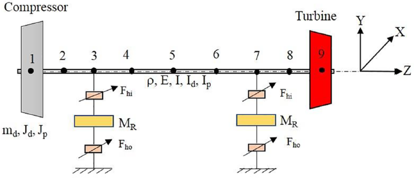
Discretization of rotor model.
The disks are considered as rigid and located at nodes 1 and 9 while the floating ring bearings are at the nodes 3 and 7. Each element has eight degrees of freedom, namely, two deflections and two slopes per each node.
The assembled system of equations by considering element stiffness, mass, and gyroscopic matrices of the shaft together with the lumped inertia and gyroscopic matrices at the two disks is represented as 27

Here, the equivalent global mass, damping, gyroscopic, and stiffness matrices are denoted by M, C, G, and K. Also the displacement vector is represented by U. The unbalance and gravity force vector at the disks is denoted by Fug and the fluid-film forces at the inner film are represented by Fhi. The motion of equation of the floating ring is expressed as

where

where
Forces in floating ring bearing
A floating ring bearing has an annular ring inserted between the journal and sleeve and are separated by a thin lubricant film. A fully circumferential feed groove is located along the bearing mid-plane and oil is fed from the journal to the sleeve through a set of feedholes placed in the ring. The coordinate system of the floating ring bearing is shown in Figure 2.
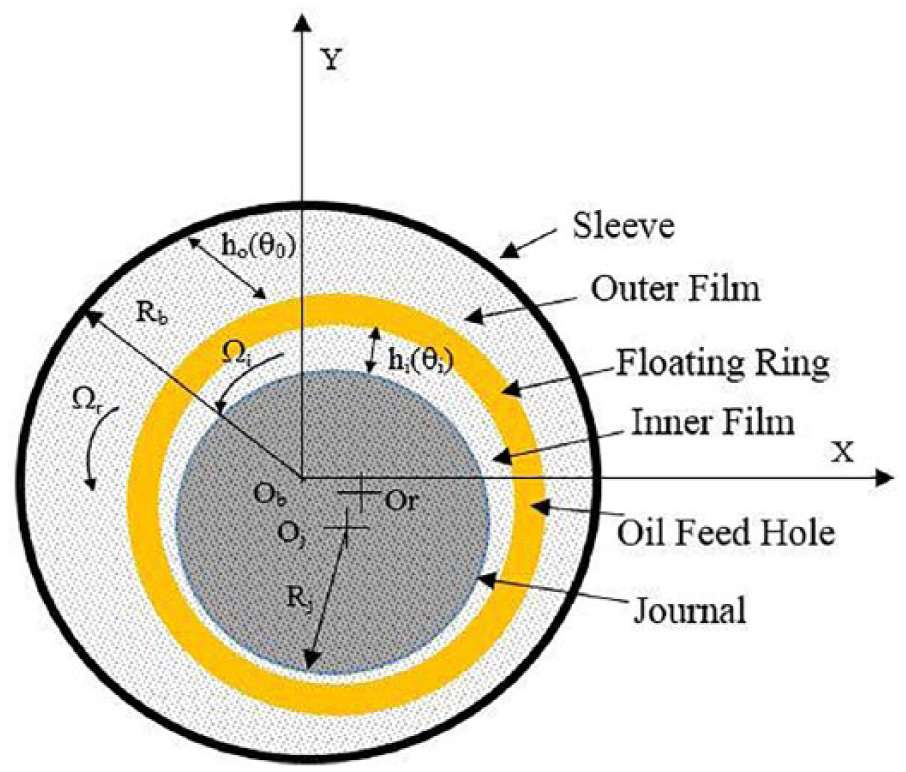
Geometry of floating ring bearing.
Reynolds equations for inner (suffix in) and outer fluid films (suffix ou) can be expressed as


By considering short bearing approximation, the x and y components of nonlinear floating ring bearing forces are expressed as 28


where fix, fiy, and fox, foy, respectively, are the component forces on the journal and bearing. Also, µ, R, Ω, C, and L, respectively, represent viscosity, radius, speed, clearance, and width, while the suffices i, o, j, and r indicate inner film, outer film, journal, and ring details.
ERF characteristics
In this work, the ER lubricant flow is idealized with Bingham model.
29
The electric field applied to the ERFs makes the particles to orient themselves along the field. The expression for the apparent viscosity is written in terms of rate of shear strain

Here, the fluid viscosity is represented as

where the ERF and field parameters are represented as A and D, respectively. In terms of applied voltage V and film thickness

As the viscosity of the ER lubricant is a function of θ, the modification to the Reynolds equation is required. On simplification of terms, the resultant equation in non-dimensional form may be written as
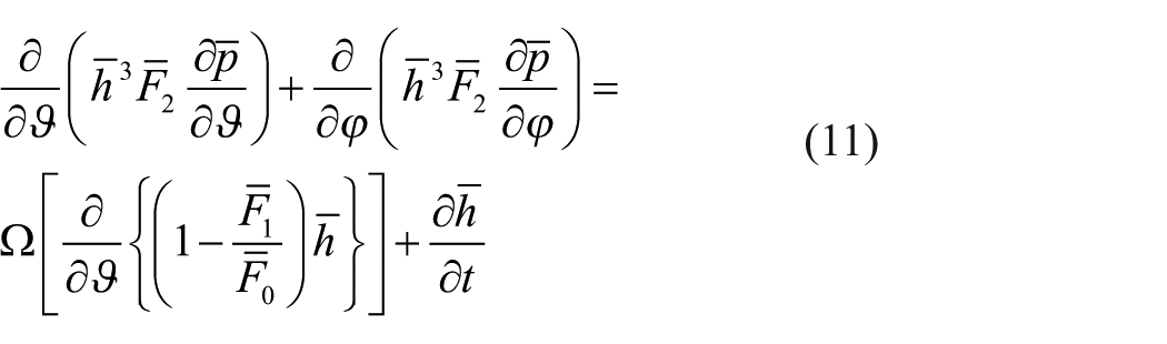
where

where the fluid-film thickness can be expressed as

Results and discussions
In order to solve the coupled differential equations, the fourth-order Runge–Kutta time integration scheme is used with all zero initial conditions. Table 1 shows the material and dimension parameters of the rotor bearing system.
Rotor bearing system material and dimensions considered. 9 .

The ERF properties considered are shown in the Table 2.
Properties of ER lubricant. 19 .

ER: electrorheological.
Figure 3 shows the Campbell diagram of the rotor system supported over the linearized floating ring bearing system. The first few critical speeds are obtained at 2500, 7200, 24,500, and 32,000 rpm, respectively.

Campbell diagram.
Effect of bearing clearances
Initially, ER fluid is not considered in the analysis of rotor-bearing system. Figures 4–6 show the time histories and its fast Fourier transform (FFT) spectrum at left bearing node with varied inner bearing clearances at a rotor speed of 5000 rpm, while the Figures 7 and 8 illustrate the responses of the system with varied outer bearing clearances.
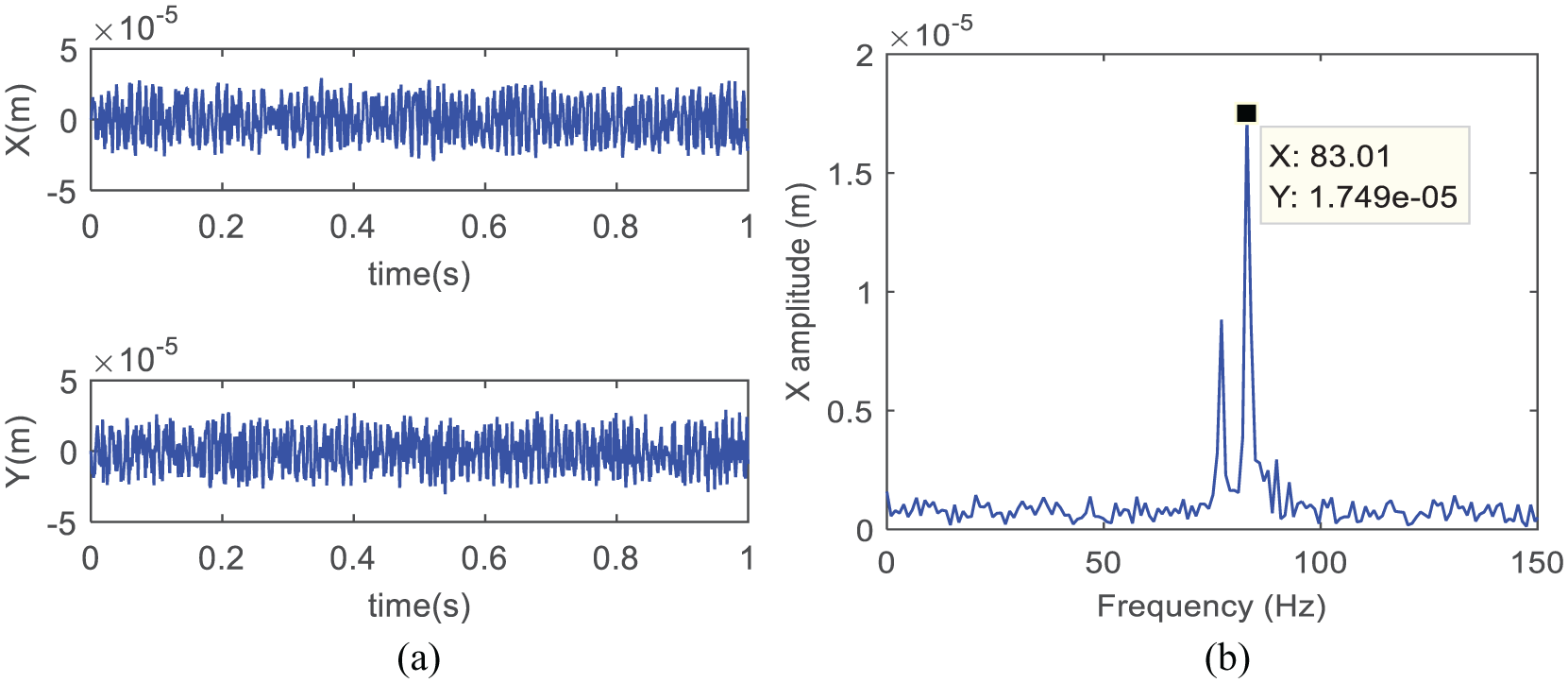
(a) Time history and (b) FFT at left bearing (Cin = 34 × m and Cou = 74 × m).
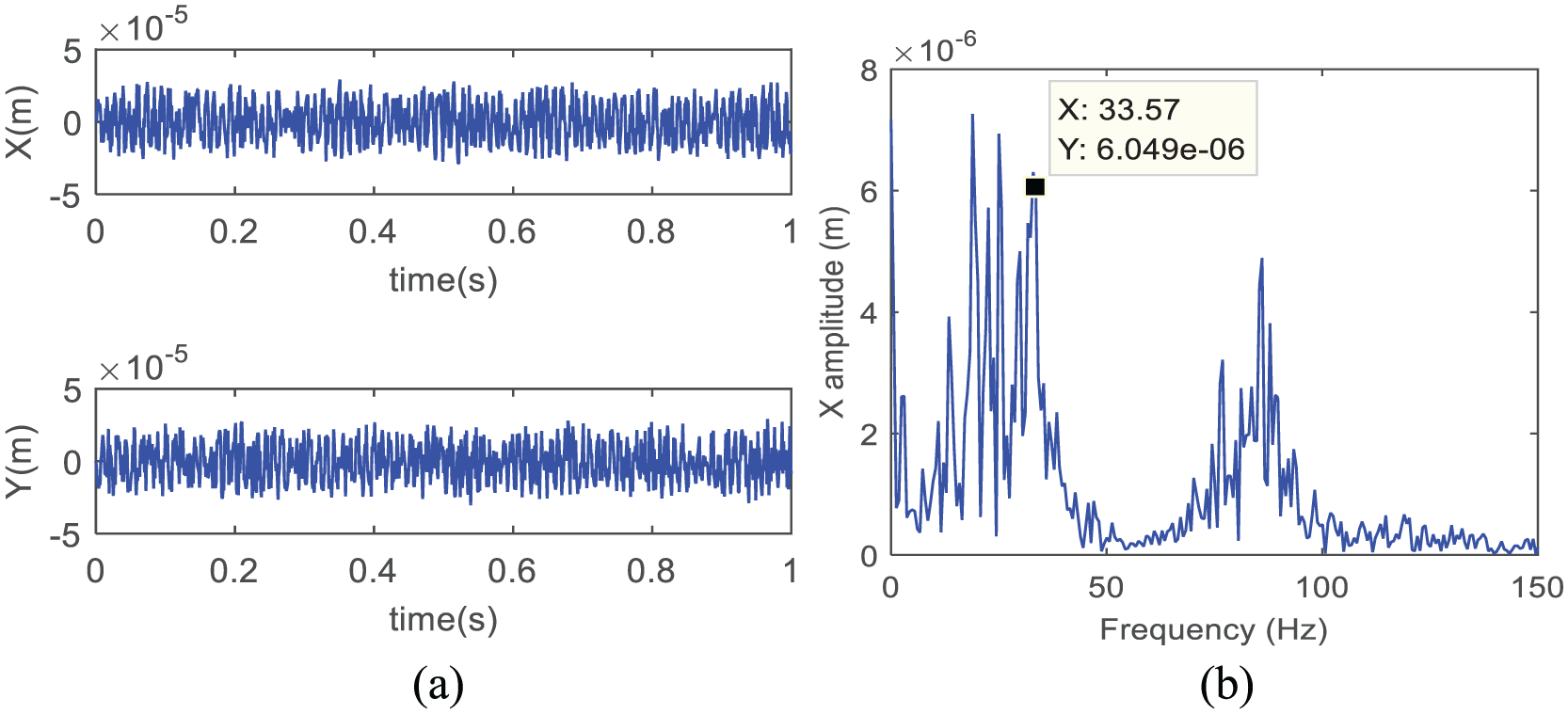
(a) Time history and (b) FFT at left bearing (Cin = 54 × m and Cou = 74 × m).

(a) Time history and (b) FFT at left bearing (Cin = 74 × m and Cou = 74 × m).

(a) Time history and (b) FFT at left bearing (Cin = 34 × m and Cou = 94 × m).
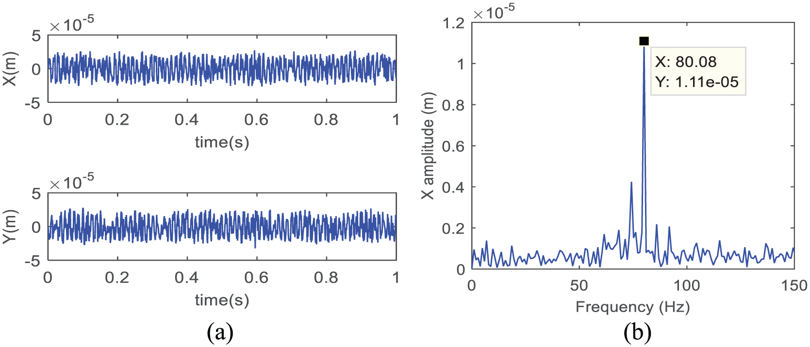
(a) Time history and (b) FFT at left bearing (Cin = 34 × m and Cou = 114 × m).
As seen from figures, the dynamic response of the system is influenced by the bearing clearances considerably; especially, the inner clearance variations violently amplify subsynchronous oscillations because as the clearance increase in the inner film, the instability in the oil film increases. Like bearing clearances, oil viscosity also has considerable effect on the unbalance response of the rotor.
ER effect
The time and frequency response of the system at a shaft speed of 25,000 rpm obtained with variable oil viscosity are shown in Figures 9 and 10. These records are for 0 and 600 V applied voltage conditions. From the frequency response, it is seen that there are three dominant peaks (components A, B, and C) occurring at frequencies 55.6, 96.68, and 421.5 Hz. Here, the peak obtained at 421.5 Hz corresponds to the critical speed of the rotor operating at 25,000 rpm. These observations are made without considering the ERF in the bearings. Later, by considering the ER effect, the analysis is carried out.
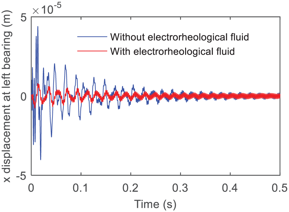
Time response with and without electrorheological fluid.

Corresponding frequency responses.
The applied electric field strength (E) is also one the important parameters which influences the dynamics of the system. The first three response amplitudes noted for different electric fields at a rotor speed of 25,000 rpm are depicted in Table 3.
First three response amplitudes for various applied electric field values.
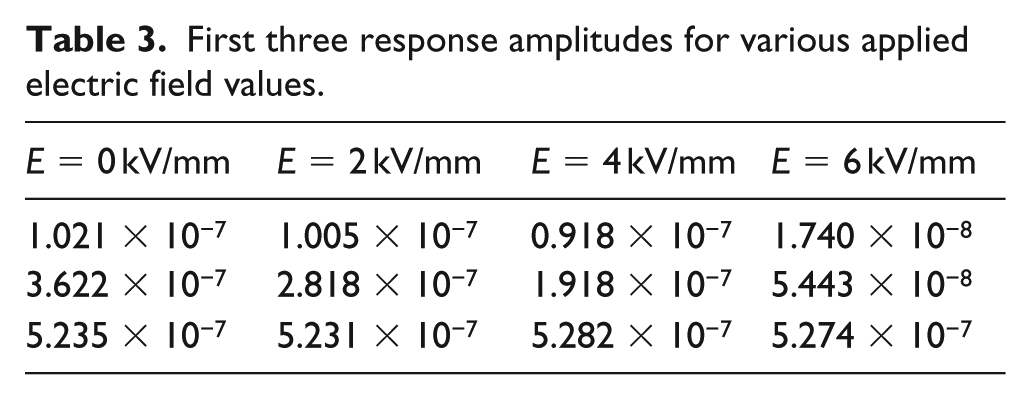
It is seen that, with the increase of the applied electric field (E), there is a decrease in the first two response amplitudes, whereas the amplitude of the third peak maintains almost constant value. The applied electric field (E) influences the response of the system considerably. Figure 11 shows the frequency responses of the system at a different applied voltage (V).
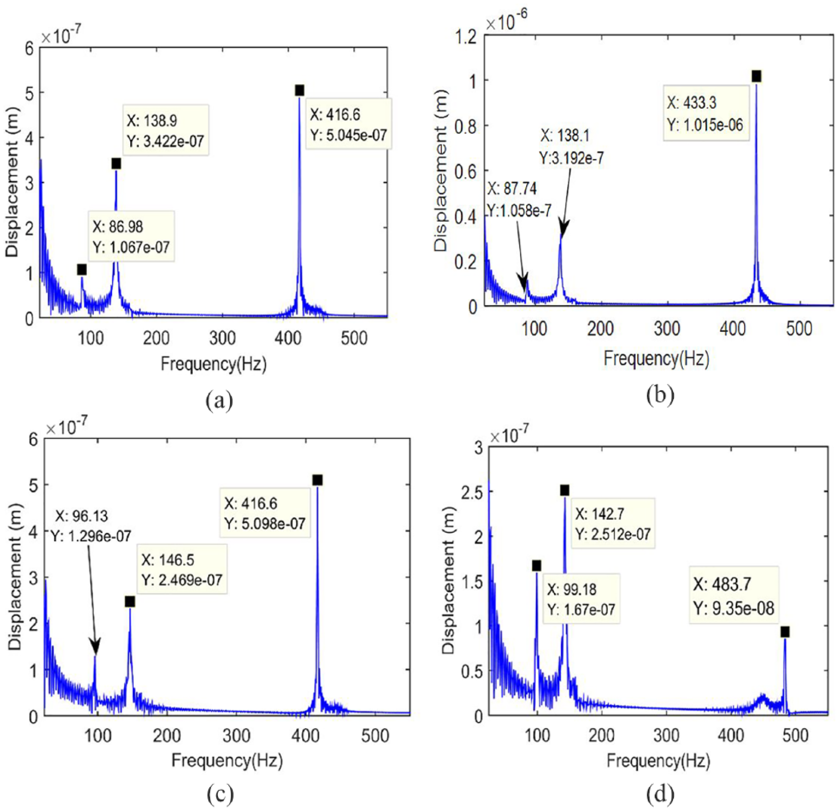
Frequency response of the system at various applied voltages: (a) V = 0 V, (b) V = 600 V, (c) V = 800 V, and (d) V = 1200 V.
It is seen that as the applied voltage increases to 800 V, the amplitudes of subsynchronous peaks of the system decrease and frequency values increase. Further increasing the applied voltage, the subsynchronous peak amplitudes are increasing whereas the dominant peak amplitude is reducing.
Conclusion
Application of ERF lubricants in the floating ring bearings of high-speed rotors has been studied in this work. The gyroscopic effects and nonlinear bearing forces were considered to analyze the rotor by finite element modeling. Initially, without considering the ER effect in the bearing, the unbalance response of the system was identified and effect of bearing clearances was illustrated. Afterward, the ER effect on the dynamic response of the system was studied. The influence of the applied voltage (V) on the response of the system was found to be considerable and concluded that as the applied electric field increases, the amplitudes in the response were getting reduced. Whereas while increasing the applied voltage, the first two peak amplitudes are changing considerably up to 800 V later, and on increasing the applied voltage, the dominant peak amplitude changes drastically. The effectiveness of the proposed control concept can be enhanced by considering additional operating conditions like heat and surrounding temperature.
Footnotes
Declaration of conflicting interests
The author(s) declared no potential conflicts of interest with respect to the research, authorship, and/or publication of this article.
Funding
The author(s) received no financial support for the research, authorship, and/or publication of this article.
