



Abstract
Continuous structures such as beams, rods and plates can be modelled by discrete mass and stiffness parameters and analysed as multi-degree-of-freedom systems. The analysis of structural vibration is necessary to obtain the natural frequencies of a structure and the response to the external excitation. In this way, it can be determined whether a particular structure will fulfil its intended function and, in addition, the results of the dynamic loadings acting on a structure can be predicted. The lack of a sober analytical research about the vibrational behaviour of the 5-MW wind turbine blade pushed us to investigate about this crucial issue, however, most of the discreet researches are concerned with the aerodynamic effects rather than structural analysis. In this article, Rayleigh–Ritz method was implemented for a typical 5-MW wind turbine blade. MATLAB codes were developed and natural frequencies were obtained for both flapwise and edgewise vibrational behaviour. A good agreement was observed between the analytical results and the manufacturer results.
Keywords
Introduction
The greater challenge for the future generations is the clean climate; one of the top promising alternatives is the use of pollution-free sources like the wind energy. The 5-MW wind turbine is considered one of the most commonly used, reliable and secure huge machine and has been on the market since 2005 for both onshore and offshore power generation source. 1 It is extremely important to investigate about the vibrational behaviour of the wind turbine blade. The fundamental natural frequencies for a 5-MW wind turbine blade were extracted and the results compared by a numerical solver FAST showing good agreement. 2 A novel computational tool was developed for the aeroelastic analysis of a National Renewable Energy Laboratory (NREL) 5-MW wind turbine blades with an alternative blade configurations to mitigate vibration and improve fatigue performance. 3 The influence of vibrations on the aerodynamic loading on the blade of a 5-MW wind turbine was investigated using the blade element-momentum and the Beddoes–Leishman (B–L) dynamic stall model. 4 A new approach to study and analyse the stresses and deformations of a 5-MW wind turbine blade under the steady-state condition has been provided, the three-dimensional model of blade was created using SOLIDWORKS and simulated numerically by ANSYS/Workbench. 5 The effect of rotor position and weight adjustment on the vibration behaviour of the drive-train system has been addressed for a 5-MW direct-drive wind turbine by considering the unbalanced magnetic pull force. 6
A variable length wind turbine blade natural frequencies were investigated and identified to avoid resonance both numerically and analytically. 7 Rayleigh’s method has been implemented to track the resonance zone 8 and the authors also studied the higher modes by finite element (FE) method. A study conducted by Ulriksen et al. 9 proposed modal and wavelet analysis–based damage identification method to a 34-m wind turbine blade as a trailing-edge deboning was introduced. A modelling study on ultrasonic guided waves propagating in composite blades was used to determine the optimal frequency and location of the transducers for ensuring wave propagation, causing the required level of energy concentration and resulting shear stress across the leading edge of the turbine’s blade. 10 An experimental analysis of the LM19-m blade has been compared with results from a FE-modelling of the same blade. For some of the higher modes, substantial discrepancies between the natural frequencies originating from the FE-modelling and the modal analysis, respectively, are observed. The aeroelastic response and performance of a 5-MW class rotating composite blade model were examined by numerically advanced coupled method based on computational fluid dynamics (CFD) and the computational flexible multi-body dynamics (CFMBD). 11 The basic dynamic characteristics of the 5-MW offshore wind energy plants (OWEP) and its environment by means of various measured signals had been discussed in Kraemer and Fritzen. 12 In this article, a further understanding for the implementation of Rayleigh–Ritz analytical method to extract the fundamental natural frequencies for both flapping and edgewise directions for a typical 5-MW wind turbine blade.
Description of the model
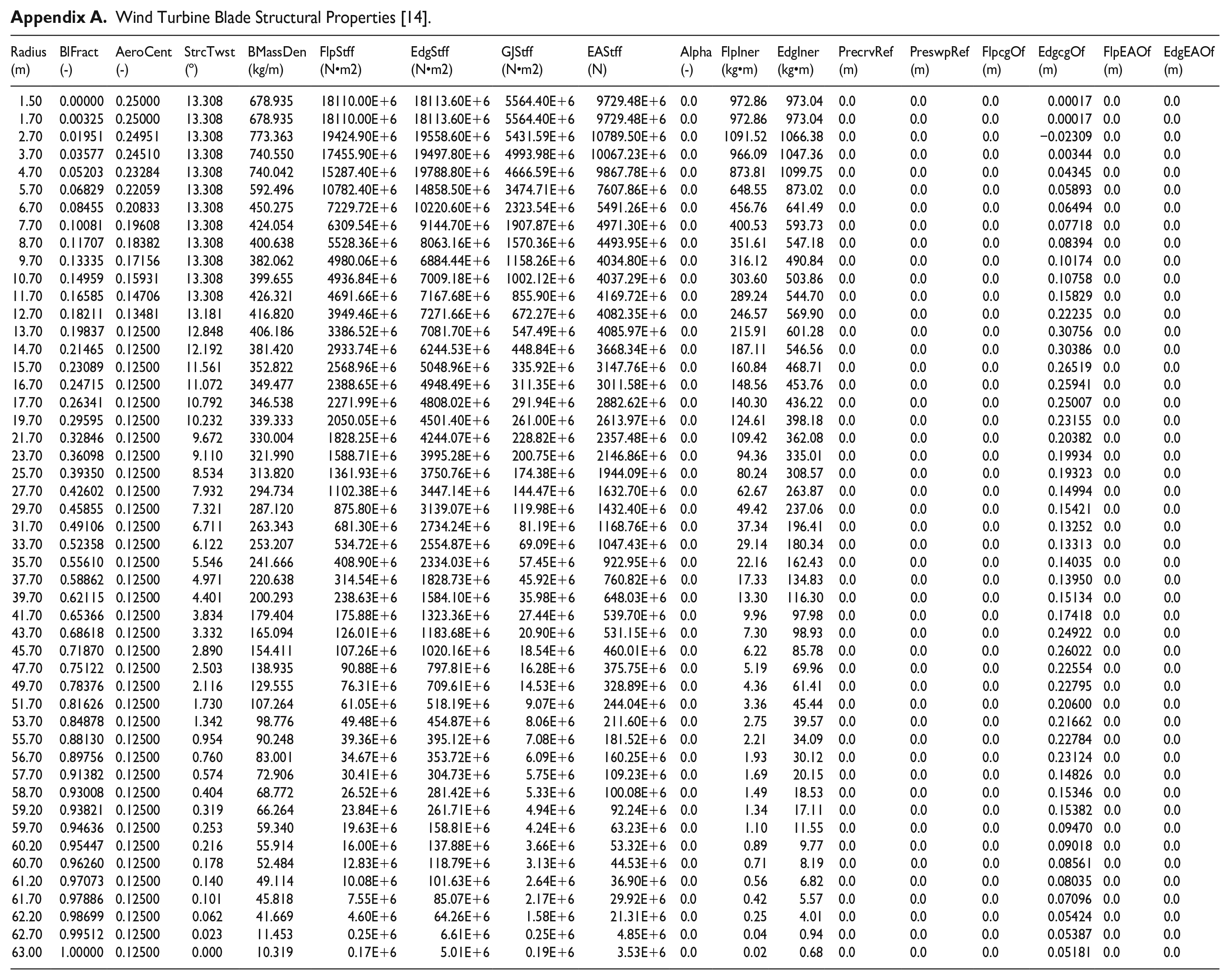
The wind turbine blade was modelled using ANSYS. The same blade will be analysed analytically by Rayleigh–Ritz method. A 5-MW NREL wind turbine blade was selected for this study, due to availability of required geometric design parameters and experimental data for verification. The blade is 61.5 m long, the geometric design parameters like mass, flexural rigidity, flapwise and edgewise stiffness with other properties are given in Appendix A. 13 The x-axis of the blade is coinciding with the longitudinal axis of the blade as shown in Figure 1. In this work, axial strains are negligible because any change in length will be a small fraction of the original length. This will imply that the beam is inextensible. Also, it implies that the Bernoulli–Euler theorem is valid, which states that the curvature of the beam is proportional to the bending moment. 14
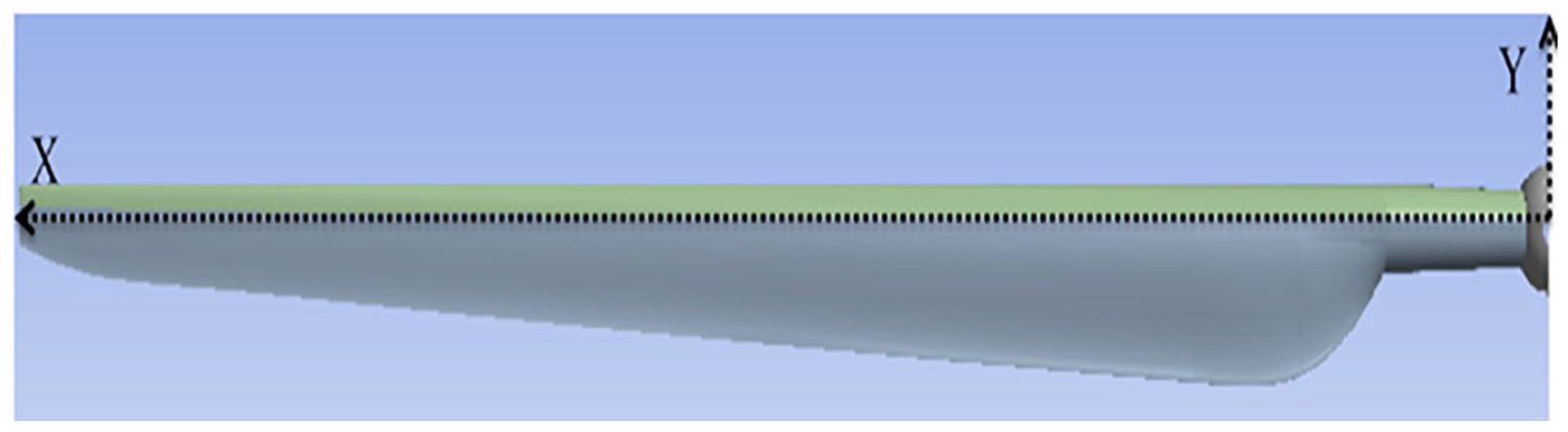
Configuration of the modelled wind turbine blade.
Boundary conditions
The wind turbine blade is treated as a cantilever beam with following boundary conditions.
At fixed (clamped) end, both deflection and slope are zero

At its free end, bending moment and shear force are zero

Rayleigh–Ritz method
The Rayleigh–Ritz method enables the researcher to reduce an infinite number of degrees-of-freedom (DOFs) of a system into a finite number, which makes analysis possible and easier. The method relies on the approximation of the possible deformation shapes of the system, following the basic idea of Rayleigh’s principle which approximates a continuous system by an equivalent single degree-of-freedom (SDOF) system via assuming a single deformation shape. The number of DOF is equal to the number of Rayleigh–Ritz modes chosen. The method can be used to determine the natural frequencies and dynamic response of beams. The configuration of the modelled wind turbine blade is illustrated in Figure 1.
Consideration of the energy in a dynamic system together with the use of the Lagrange equation is a very powerful method of analysis for certain physically complex systems.
15
This is an energy method that allows the equations of motion to be written in terms of any set of generalized coordinates. Generalized coordinates are a set of independent parameters that completely specify the system location and they are independent of each other. The fundamental equation of motion for a multi-DOF can be derived from Lagrange’s equation
16
and can be written in terms of the generalized coordinates that describes the position of the system

where
For a conservative system,

When dealing with free vibration under small displacements, it may be that

where
Rotary inertia and shear effects must be taken into account in the analysis of high-frequency vibration of all beams. 15 For this study, rotary inertia effects can be ignored due to low rotational velocity of the wind turbine as it is rated as 12 r/min. 13 Therefore, the kinetic energy of the beam is given by

By neglecting shear deformation, strain energy of the blade will be

where

where


where


Substituting equations (9) and (10) into Lagrange’s equation (5), one can obtain the total differential equation of the free vibration

Assuming solution for equation in the form

where

Equation (15) contains a set of characteristic equations and can be solved for

where
Associated with each Eigen value is a set of values of

The characteristic equations given by equation (17) can be easily put into a form suitable for numerical calculation, using matrix notation. If the beam is divided into

where

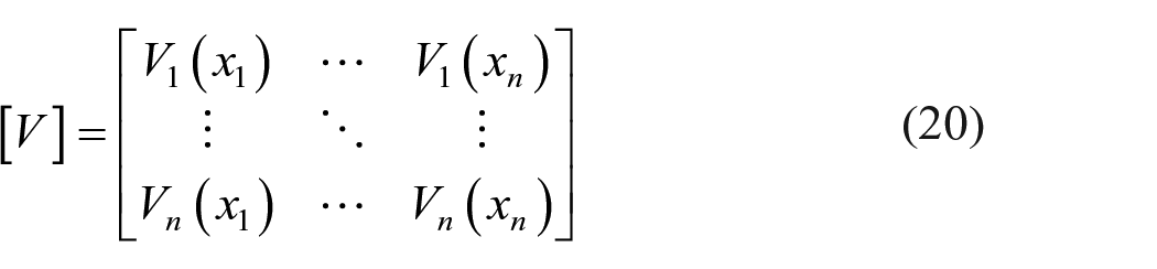
and

By substituting equations (18) and (19) into equation (21) we get
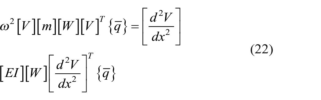
The complete solution of the problem of free vibration of any system would require the determination of all the natural frequencies and of the mode shape associated with each. In practice, it is often necessary to know only a few of the natural frequencies, and sometimes only one. Usually the lowest frequencies are the most important. 17
Since the wind turbine blade is a cantilever beam, the following polynomial expression will be used for the mode shapes functions
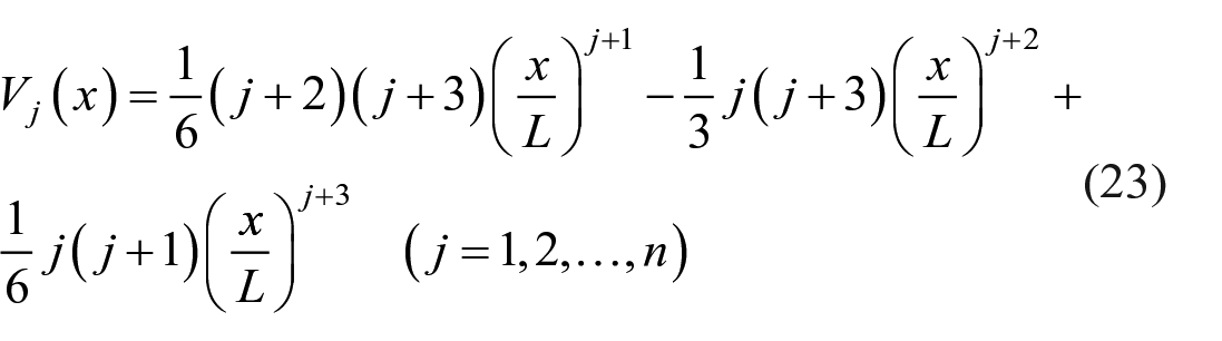
The 61.5-m long wind turbine blade is divided into 50 equal segments, 51 spanwise stations will be created with each of 1.23 m starting from the root to the tip of the blade as shown in Figure 2.
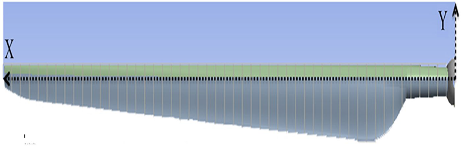
The modelled blade divided into 50 equal segments.
Flapwise and edgewise vibrations
Two main types of vibration occur in wind turbine blades, flapwise and edgewise. Figure 3 shows flapwise direction (F–F) and edgewise direction (E–E). The first flapwise natural bending frequency of the blade can resonate with the wind turbine tower first bending frequency whereas the second natural bending frequency of the blade is in most cases so high that it no longer interferes. 18 The second natural frequency of interest is therefore the first edgewise natural frequency.
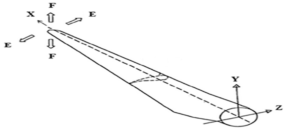
Flapwise (F–F) and edgewise (E–E) vibration directions of a typical wind turbine blade.
By assuming two mode shape functions, the lateral displacement matrix equation is given by

where


where
The displacement second-derivative matrix


Mass density of the wind turbine blade and both the flapwise and edgewise flexural rigidity are given in Appendix A.
13
The matrix of weighting coefficients

where (a–b) is the length of the blade which equals to 61.5 m with
Results
Using MATLAB, equation (22) was solved for first two flapwise and edgewise natural frequencies. Results are shown in Table 1.
Natural frequencies comparison for two modes.

Big error is noticed by comparing analytical results to manufacturer results, 13 especially for the second flapping frequency. Less errors are found for the first two edgewise frequencies. By plugging the three mode shape functions and solving it again, results are improving. Same procedure was followed by assuming higher mode shapes until reaching sixth mode shapes given by

And its second derivatives with respect to

Natural frequencies converge towards the manufacturer results and errors have been decreased considerably. Results for natural frequencies after applying sixth mode shape are given in Table 2.
Natural frequencies comparison for six mode shapes.
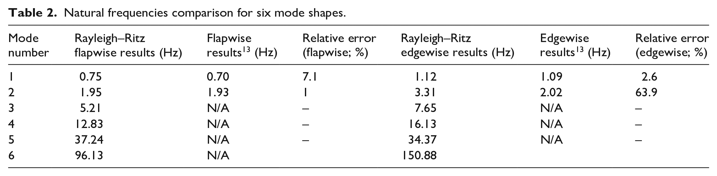
It is clear from the results of Rayleigh–Ritz method that convergence of the fundamental natural frequencies of the modelled wind turbine blade been achieved after the fifth mode shape function for both the flapwise and edgewise vibrations. It is noticed that the first natural frequency is converging steadily while this is not the case for higher mode natural frequencies. This is mainly because Rayleigh–Ritz method is an extension of Rayleigh’s principle which represents a technique for estimating the lowest Eigenvalue, that is, the first natural frequency. 19 It is also noticed that the relative error has reduced significantly for the second flapping mode but not for the second edging mode this is mainly referred to the designed structural properties of the wind turbine blade stiffness which has much higher values for edgewise as compared with flapwise stiffness as shown in Appendix A, in other words, the deflection in the edgewise direction is limited as compared with that in the flapwise direction, moreover, the second edgewise mode is in fact the fourth natural frequency and as mentioned earlier the Rayleigh–Ritz method has superior accuracy for the lowest fundamental natural frequencies.
Discussion of the analytical analysis
The Rayleigh–Ritz method has been implemented to perform analytical analysis for the wind turbine blade. Properties of the blade were provided by NREL, a renowned wind turbine manufacturer. A MATLAB code was developed for defining both flapwise and edgewise natural frequencies for the mode shapes. Convergence of natural frequencies was achieved by six mode shapes. Relative Rayleigh–Ritz method errors as compared with the manufacturer results for clean blade were 7% and 1% for the first and second flapwise frequencies, respectively, and less than 3% for the first edgewise frequency.
Conclusion
This article started with a description of the wind turbine model. The Rayleigh–Ritz method was then introduced together with all the key equations and matrices. The solution procedure was started by two mode shapes. Mass and stiffness matrices were established along with other relevant matrices according to the properties provided by the blade manufacture. The matrices were then fed into MATLAB programme code developed for Rayleigh–Ritz method. The results of natural frequencies were compared with results obtained by the manufacturer. The procedure was repeated by increasing the number of the mode shapes until convergence has achieved by five mode shapes, which was for the clean blade. Results of analytical analysis for the three vibration modes agree well with the manufacturer results knowing that the Rayleigh–Ritz method is most suitable for the lower modes, namely the first mode.
Footnotes
Appendix
Wind Turbine Blade Structural Properties [14].
| Radius | BlFract | AeroCent | StrcTwst | BMassDen | FlpStff | EdgStff | GJStff | EAStff | Alpha | FlpIner | EdgIner | PrecrvRef | PreswpRef | FlpcgOf | EdgcgOf | FlpEAOf | EdgEAOf |
|---|---|---|---|---|---|---|---|---|---|---|---|---|---|---|---|---|---|
| (m) | (-) | (-) | (°) | (kg/m) | (N•m2) | (N•m2) | (N•m2) | (N) | (-) | (kg•m) | (kg•m) | (m) | (m) | (m) | (m) | (m) | (m) |
| 1.50 | 0.00000 | 0.25000 | 13.308 | 678.935 | 18110.00E+6 | 18113.60E+6 | 5564.40E+6 | 9729.48E+6 | 0.0 | 972.86 | 973.04 | 0.0 | 0.0 | 0.0 | 0.00017 | 0.0 | 0.0 |
| 1.70 | 0.00325 | 0.25000 | 13.308 | 678.935 | 18110.00E+6 | 18113.60E+6 | 5564.40E+6 | 9729.48E+6 | 0.0 | 972.86 | 973.04 | 0.0 | 0.0 | 0.0 | 0.00017 | 0.0 | 0.0 |
| 2.70 | 0.01951 | 0.24951 | 13.308 | 773.363 | 19424.90E+6 | 19558.60E+6 | 5431.59E+6 | 10789.50E+6 | 0.0 | 1091.52 | 1066.38 | 0.0 | 0.0 | 0.0 | −0.02309 | 0.0 | 0.0 |
| 3.70 | 0.03577 | 0.24510 | 13.308 | 740.550 | 17455.90E+6 | 19497.80E+6 | 4993.98E+6 | 10067.23E+6 | 0.0 | 966.09 | 1047.36 | 0.0 | 0.0 | 0.0 | 0.00344 | 0.0 | 0.0 |
| 4.70 | 0.05203 | 0.23284 | 13.308 | 740.042 | 15287.40E+6 | 19788.80E+6 | 4666.59E+6 | 9867.78E+6 | 0.0 | 873.81 | 1099.75 | 0.0 | 0.0 | 0.0 | 0.04345 | 0.0 | 0.0 |
| 5.70 | 0.06829 | 0.22059 | 13.308 | 592.496 | 10782.40E+6 | 14858.50E+6 | 3474.71E+6 | 7607.86E+6 | 0.0 | 648.55 | 873.02 | 0.0 | 0.0 | 0.0 | 0.05893 | 0.0 | 0.0 |
| 6.70 | 0.08455 | 0.20833 | 13.308 | 450.275 | 7229.72E+6 | 10220.60E+6 | 2323.54E+6 | 5491.26E+6 | 0.0 | 456.76 | 641.49 | 0.0 | 0.0 | 0.0 | 0.06494 | 0.0 | 0.0 |
| 7.70 | 0.10081 | 0.19608 | 13.308 | 424.054 | 6309.54E+6 | 9144.70E+6 | 1907.87E+6 | 4971.30E+6 | 0.0 | 400.53 | 593.73 | 0.0 | 0.0 | 0.0 | 0.07718 | 0.0 | 0.0 |
| 8.70 | 0.11707 | 0.18382 | 13.308 | 400.638 | 5528.36E+6 | 8063.16E+6 | 1570.36E+6 | 4493.95E+6 | 0.0 | 351.61 | 547.18 | 0.0 | 0.0 | 0.0 | 0.08394 | 0.0 | 0.0 |
| 9.70 | 0.13335 | 0.17156 | 13.308 | 382.062 | 4980.06E+6 | 6884.44E+6 | 1158.26E+6 | 4034.80E+6 | 0.0 | 316.12 | 490.84 | 0.0 | 0.0 | 0.0 | 0.10174 | 0.0 | 0.0 |
| 10.70 | 0.14959 | 0.15931 | 13.308 | 399.655 | 4936.84E+6 | 7009.18E+6 | 1002.12E+6 | 4037.29E+6 | 0.0 | 303.60 | 503.86 | 0.0 | 0.0 | 0.0 | 0.10758 | 0.0 | 0.0 |
| 11.70 | 0.16585 | 0.14706 | 13.308 | 426.321 | 4691.66E+6 | 7167.68E+6 | 855.90E+6 | 4169.72E+6 | 0.0 | 289.24 | 544.70 | 0.0 | 0.0 | 0.0 | 0.15829 | 0.0 | 0.0 |
| 12.70 | 0.18211 | 0.13481 | 13.181 | 416.820 | 3949.46E+6 | 7271.66E+6 | 672.27E+6 | 4082.35E+6 | 0.0 | 246.57 | 569.90 | 0.0 | 0.0 | 0.0 | 0.22235 | 0.0 | 0.0 |
| 13.70 | 0.19837 | 0.12500 | 12.848 | 406.186 | 3386.52E+6 | 7081.70E+6 | 547.49E+6 | 4085.97E+6 | 0.0 | 215.91 | 601.28 | 0.0 | 0.0 | 0.0 | 0.30756 | 0.0 | 0.0 |
| 14.70 | 0.21465 | 0.12500 | 12.192 | 381.420 | 2933.74E+6 | 6244.53E+6 | 448.84E+6 | 3668.34E+6 | 0.0 | 187.11 | 546.56 | 0.0 | 0.0 | 0.0 | 0.30386 | 0.0 | 0.0 |
| 15.70 | 0.23089 | 0.12500 | 11.561 | 352.822 | 2568.96E+6 | 5048.96E+6 | 335.92E+6 | 3147.76E+6 | 0.0 | 160.84 | 468.71 | 0.0 | 0.0 | 0.0 | 0.26519 | 0.0 | 0.0 |
| 16.70 | 0.24715 | 0.12500 | 11.072 | 349.477 | 2388.65E+6 | 4948.49E+6 | 311.35E+6 | 3011.58E+6 | 0.0 | 148.56 | 453.76 | 0.0 | 0.0 | 0.0 | 0.25941 | 0.0 | 0.0 |
| 17.70 | 0.26341 | 0.12500 | 10.792 | 346.538 | 2271.99E+6 | 4808.02E+6 | 291.94E+6 | 2882.62E+6 | 0.0 | 140.30 | 436.22 | 0.0 | 0.0 | 0.0 | 0.25007 | 0.0 | 0.0 |
| 19.70 | 0.29595 | 0.12500 | 10.232 | 339.333 | 2050.05E+6 | 4501.40E+6 | 261.00E+6 | 2613.97E+6 | 0.0 | 124.61 | 398.18 | 0.0 | 0.0 | 0.0 | 0.23155 | 0.0 | 0.0 |
| 21.70 | 0.32846 | 0.12500 | 9.672 | 330.004 | 1828.25E+6 | 4244.07E+6 | 228.82E+6 | 2357.48E+6 | 0.0 | 109.42 | 362.08 | 0.0 | 0.0 | 0.0 | 0.20382 | 0.0 | 0.0 |
| 23.70 | 0.36098 | 0.12500 | 9.110 | 321.990 | 1588.71E+6 | 3995.28E+6 | 200.75E+6 | 2146.86E+6 | 0.0 | 94.36 | 335.01 | 0.0 | 0.0 | 0.0 | 0.19934 | 0.0 | 0.0 |
| 25.70 | 0.39350 | 0.12500 | 8.534 | 313.820 | 1361.93E+6 | 3750.76E+6 | 174.38E+6 | 1944.09E+6 | 0.0 | 80.24 | 308.57 | 0.0 | 0.0 | 0.0 | 0.19323 | 0.0 | 0.0 |
| 27.70 | 0.42602 | 0.12500 | 7.932 | 294.734 | 1102.38E+6 | 3447.14E+6 | 144.47E+6 | 1632.70E+6 | 0.0 | 62.67 | 263.87 | 0.0 | 0.0 | 0.0 | 0.14994 | 0.0 | 0.0 |
| 29.70 | 0.45855 | 0.12500 | 7.321 | 287.120 | 875.80E+6 | 3139.07E+6 | 119.98E+6 | 1432.40E+6 | 0.0 | 49.42 | 237.06 | 0.0 | 0.0 | 0.0 | 0.15421 | 0.0 | 0.0 |
| 31.70 | 0.49106 | 0.12500 | 6.711 | 263.343 | 681.30E+6 | 2734.24E+6 | 81.19E+6 | 1168.76E+6 | 0.0 | 37.34 | 196.41 | 0.0 | 0.0 | 0.0 | 0.13252 | 0.0 | 0.0 |
| 33.70 | 0.52358 | 0.12500 | 6.122 | 253.207 | 534.72E+6 | 2554.87E+6 | 69.09E+6 | 1047.43E+6 | 0.0 | 29.14 | 180.34 | 0.0 | 0.0 | 0.0 | 0.13313 | 0.0 | 0.0 |
| 35.70 | 0.55610 | 0.12500 | 5.546 | 241.666 | 408.90E+6 | 2334.03E+6 | 57.45E+6 | 922.95E+6 | 0.0 | 22.16 | 162.43 | 0.0 | 0.0 | 0.0 | 0.14035 | 0.0 | 0.0 |
| 37.70 | 0.58862 | 0.12500 | 4.971 | 220.638 | 314.54E+6 | 1828.73E+6 | 45.92E+6 | 760.82E+6 | 0.0 | 17.33 | 134.83 | 0.0 | 0.0 | 0.0 | 0.13950 | 0.0 | 0.0 |
| 39.70 | 0.62115 | 0.12500 | 4.401 | 200.293 | 238.63E+6 | 1584.10E+6 | 35.98E+6 | 648.03E+6 | 0.0 | 13.30 | 116.30 | 0.0 | 0.0 | 0.0 | 0.15134 | 0.0 | 0.0 |
| 41.70 | 0.65366 | 0.12500 | 3.834 | 179.404 | 175.88E+6 | 1323.36E+6 | 27.44E+6 | 539.70E+6 | 0.0 | 9.96 | 97.98 | 0.0 | 0.0 | 0.0 | 0.17418 | 0.0 | 0.0 |
| 43.70 | 0.68618 | 0.12500 | 3.332 | 165.094 | 126.01E+6 | 1183.68E+6 | 20.90E+6 | 531.15E+6 | 0.0 | 7.30 | 98.93 | 0.0 | 0.0 | 0.0 | 0.24922 | 0.0 | 0.0 |
| 45.70 | 0.71870 | 0.12500 | 2.890 | 154.411 | 107.26E+6 | 1020.16E+6 | 18.54E+6 | 460.01E+6 | 0.0 | 6.22 | 85.78 | 0.0 | 0.0 | 0.0 | 0.26022 | 0.0 | 0.0 |
| 47.70 | 0.75122 | 0.12500 | 2.503 | 138.935 | 90.88E+6 | 797.81E+6 | 16.28E+6 | 375.75E+6 | 0.0 | 5.19 | 69.96 | 0.0 | 0.0 | 0.0 | 0.22554 | 0.0 | 0.0 |
| 49.70 | 0.78376 | 0.12500 | 2.116 | 129.555 | 76.31E+6 | 709.61E+6 | 14.53E+6 | 328.89E+6 | 0.0 | 4.36 | 61.41 | 0.0 | 0.0 | 0.0 | 0.22795 | 0.0 | 0.0 |
| 51.70 | 0.81626 | 0.12500 | 1.730 | 107.264 | 61.05E+6 | 518.19E+6 | 9.07E+6 | 244.04E+6 | 0.0 | 3.36 | 45.44 | 0.0 | 0.0 | 0.0 | 0.20600 | 0.0 | 0.0 |
| 53.70 | 0.84878 | 0.12500 | 1.342 | 98.776 | 49.48E+6 | 454.87E+6 | 8.06E+6 | 211.60E+6 | 0.0 | 2.75 | 39.57 | 0.0 | 0.0 | 0.0 | 0.21662 | 0.0 | 0.0 |
| 55.70 | 0.88130 | 0.12500 | 0.954 | 90.248 | 39.36E+6 | 395.12E+6 | 7.08E+6 | 181.52E+6 | 0.0 | 2.21 | 34.09 | 0.0 | 0.0 | 0.0 | 0.22784 | 0.0 | 0.0 |
| 56.70 | 0.89756 | 0.12500 | 0.760 | 83.001 | 34.67E+6 | 353.72E+6 | 6.09E+6 | 160.25E+6 | 0.0 | 1.93 | 30.12 | 0.0 | 0.0 | 0.0 | 0.23124 | 0.0 | 0.0 |
| 57.70 | 0.91382 | 0.12500 | 0.574 | 72.906 | 30.41E+6 | 304.73E+6 | 5.75E+6 | 109.23E+6 | 0.0 | 1.69 | 20.15 | 0.0 | 0.0 | 0.0 | 0.14826 | 0.0 | 0.0 |
| 58.70 | 0.93008 | 0.12500 | 0.404 | 68.772 | 26.52E+6 | 281.42E+6 | 5.33E+6 | 100.08E+6 | 0.0 | 1.49 | 18.53 | 0.0 | 0.0 | 0.0 | 0.15346 | 0.0 | 0.0 |
| 59.20 | 0.93821 | 0.12500 | 0.319 | 66.264 | 23.84E+6 | 261.71E+6 | 4.94E+6 | 92.24E+6 | 0.0 | 1.34 | 17.11 | 0.0 | 0.0 | 0.0 | 0.15382 | 0.0 | 0.0 |
| 59.70 | 0.94636 | 0.12500 | 0.253 | 59.340 | 19.63E+6 | 158.81E+6 | 4.24E+6 | 63.23E+6 | 0.0 | 1.10 | 11.55 | 0.0 | 0.0 | 0.0 | 0.09470 | 0.0 | 0.0 |
| 60.20 | 0.95447 | 0.12500 | 0.216 | 55.914 | 16.00E+6 | 137.88E+6 | 3.66E+6 | 53.32E+6 | 0.0 | 0.89 | 9.77 | 0.0 | 0.0 | 0.0 | 0.09018 | 0.0 | 0.0 |
| 60.70 | 0.96260 | 0.12500 | 0.178 | 52.484 | 12.83E+6 | 118.79E+6 | 3.13E+6 | 44.53E+6 | 0.0 | 0.71 | 8.19 | 0.0 | 0.0 | 0.0 | 0.08561 | 0.0 | 0.0 |
| 61.20 | 0.97073 | 0.12500 | 0.140 | 49.114 | 10.08E+6 | 101.63E+6 | 2.64E+6 | 36.90E+6 | 0.0 | 0.56 | 6.82 | 0.0 | 0.0 | 0.0 | 0.08035 | 0.0 | 0.0 |
| 61.70 | 0.97886 | 0.12500 | 0.101 | 45.818 | 7.55E+6 | 85.07E+6 | 2.17E+6 | 29.92E+6 | 0.0 | 0.42 | 5.57 | 0.0 | 0.0 | 0.0 | 0.07096 | 0.0 | 0.0 |
| 62.20 | 0.98699 | 0.12500 | 0.062 | 41.669 | 4.60E+6 | 64.26E+6 | 1.58E+6 | 21.31E+6 | 0.0 | 0.25 | 4.01 | 0.0 | 0.0 | 0.0 | 0.05424 | 0.0 | 0.0 |
| 62.70 | 0.99512 | 0.12500 | 0.023 | 11.453 | 0.25E+6 | 6.61E+6 | 0.25E+6 | 4.85E+6 | 0.0 | 0.04 | 0.94 | 0.0 | 0.0 | 0.0 | 0.05387 | 0.0 | 0.0 |
| 63.00 | 1.00000 | 0.12500 | 0.000 | 10.319 | 0.17E+6 | 5.01E+6 | 0.19E+6 | 3.53E+6 | 0.0 | 0.02 | 0.68 | 0.0 | 0.0 | 0.0 | 0.05181 | 0.0 | 0.0 |
Declaration of conflicting interests
The author(s) declared no potential conflicts of interest with respect to the research, authorship and/or publication of this article.
Funding
The author(s) received no financial support for the research, authorship and/or publication of this article.
