
Abstract
In automobiles suspension system, laminated springs are widely used for the absorption of shock and vibration. These laminated springs account for approximately 10%–20% of the unsprung weight of the vehicle. It has been found that composite material is used to reduce the weight of the vehicle in order to obtain better efficiency. Therefore, in the current research work, composite material is used for the fabrication of laminated spring. Among the various types of glass fiber available, the C-glass fiber has been widely used due to its better corrosion resistant property. Commercial software package ANSYS is used to optimize the composite-laminated spring. The optimized leaf spring is then fabricated by the hand layup method. It was found that the spring with composite graduated leaf resulted in 40% reduction in weight than the spring with steel graduated leaf. Similarly, the stress concentration and deformation values are reduced by 76.39% and 50% in comparison with those of steel graduated leaf. The composite-laminated spring showed better damping property and also resulted in less transmission of force to the chassis of the vehicle. The noise induced by the composite-laminated spring is also reduced in comparison with steel graduated leaf. Finally, a composite-laminated spring is found to be lighter in weight and with better noise, vibration, and harshness in comparison with steel graduated leaf. Thus, it is found to be best suited for an electric vehicle.
Keywords
Introduction
Leaf spring is considered to be the major element of the suspension system, which comprises 10%–20% of the unsprung weight of the vehicle. 1 Sometimes it is also referred as laminated spring. It is basically used to absorb shock and vibration. Sometimes it gets deflected whenever any bump load is experienced by the wheel due to which less amount of load gets transferred to the automobile chassis. Moreover, the light weight design of leaf spring not only results in less fuel consumption but also improves the comfort level.
In the past few years, several research works have been carried out in the area of design, analysis, and optimization of leaf springs. Much effort has been made by several automobile industries in replacing the material of leaf spring with composite material for weight reduction 2 and cost-effectiveness. 3 –5 Corvi 6 developed a program as a preliminary approach for the design of a composite leaf spring in automobiles and also studied the effect of different parameters on the behavior of leaf spring. Shokrieh and Rezaei 7 optimized the glass fiber–reinforced composite leaf spring made on the basis of shape in order to obtain a greater reduction in weight. They replaced a steel four-leafed spring of a passenger car with the composite. Kumar and Teja 8 designed and used an E-Glass/Epoxy Mono Composite leaf spring instead of a steel leaf spring. The weight was optimized and analyzed with a proper selection of design parameters. Then, it was modeled using Pro/E and analyzed using ANSYS software. An extensive investigation of the leaf spring based on material selection, method of fabrication, design, and analysis using CAD software was carried out by Jancirani and Assarudeen. 9 Mostly fiber-reinforced composites were experimentally investigated. Suprith et al. 10 performed a static analysis of a composite, steel, and a hybrid leaf spring using ANSYS for a commercial vehicle and fatigue analysis of a steel leaf spring. They found that hybrid leaf spring is the best among the three kinds of leaf springs. Singh and Brar 11 successfully fabricated and tested two different types of composite specimens for replacing steel leaf spring in an automobile: one is Al (7075) reinforced with 25% boron carbide (B4C) and the other is carbon/epoxy composite fabricated by the stir casting technique and hand layup method. In order to determine the mechanical properties, tensile, flexural, and hardness tests were carried out. Saini and Rao 12 used the E-glass and S-glass fiber composite spring to reduce the weight of the Maruti 800 passenger vehicle. The design and optimization of E-Glass/epoxy fiber–reinforced leaf spring for a solar-powered car was carried out by Sancaktar and Gratton. 13 Shankar and Vijayarangan 14 used a low-cost fabrication technique for developing a glass fiber–reinforced composite with end joints properly bonded with adhesives. Design was done using a C-language-based computer algorithm and analysis using ANSYS. Both analytical and experimental validations were carried out. Similarly, a monocomposite leaf spring made of glass fiber reinforced with epoxy and flayash was fabricated and tested experimentally by Thippesh 15 to replace the steel leaf spring. He found about 80% reduction in weight with increase in natural frequency and also a subsequent reduction in stress, thereby achieving weight reduction with proper optimization. Aswini and Mohan Rao 16 provided an overview on the design and analysis aspect of leaf springs using different kinds of fiber-reinforced composites. They also came up with the conclusion that conventional steel leaf spring of automobiles can be very well replaced with the composites as far as strength, light weight, and vibrations are considered. Kueh and Faris 17 studied the static and fatigue behavior of glass/epoxy- and glass/vinyl ester–based composites and steel leaf springs using ANSYS 12 software for especially transportation industries. They observed that the deflection and bending stresses were less but with high fatigue life cycles. Priority was given to the variation in material selection and layup sequence. Glass/vinyl ester–reinforced composites gave better fatigue properties in comparison with glass/epoxy-reinforced composite leaf spring.
Rajendran and Vijayarangan 18 used genetic algorithm for optimization of leaf spring. They obtained a 75.6% reduction in weight of a composite leaf spring with proper optimization. Similarly, Yang et al. 19 determined the stiffness of leaf spring by developing a theoretical model based on energy approach and composite mechanics. The proposed stiffness model gave better results in comparison with finite element analysis. Dutt et al. 20 performed the analysis of the design and strength of a glass fiber–reinforced composite parabolic leaf spring under fatigue and structural load conditions. The only difference between normal leaf spring and parabolic leaf spring is the use of less number of leaves for the latter case. After the tests, both the stress and mass values were significantly reduced for composite parabolic leaf spring. Ismael 21 performed the static analysis of a hybrid fiber-reinforced composite and a steel leaf spring and also suggested different methods of fabricating leaf springs. Optimization of the leaf spring was carried out using finite element analysis through ANSYS 14 software.
If the natural frequency is less than the road frequency, then it creates resonance, which increases the amplitude of the laminated spring. Due to the increased amplitude of the laminated spring, it transmits additional vibration to the body of the vehicle, which creates disturbance to the passengers. The maximum frequency of the road irregularity is usually 12 Hz.17 Thus, the natural frequency of the laminated spring must be greater than 12 Hz to avoid the resonance and to provide a better comfortable ride to the passengers.
In this research work, ANSYS was used to optimize the load-carrying capacity of the laminated spring. The optimized composite-laminated spring was then fabricated by the hand layup technique, and as the eye of the master leaf was difficult to fabricate by this procedure, the conventional steel was used as the master laminated spring and composite C-glass was used as the graduated leaf. The load versus deformation and load versus stress curves were obtained. The vibration and noise level of steel and composite springs was determined using an accelerometer and a sound-level meter, respectively.
Materials and methods
The leaf spring is generally placed at the bottom of the suspension system and is open to the environment, due to which it is always in contact with mud, water, humidity, varying temperature, and so on. Thus, it may loose its mechanical properties. The C-glass has good corrosion resistance than the other types of glass fibers. Therefore, in the present research work, woven C-glass fibers of density 1666.66 kg/m3 from Owens Corning, India, were used. Epoxy labeled as Lapox L–12 (diglycidyl ether of bisphenol A) of density 1160 kg/m3 and hardener named K6 (triethylene tetra amine) procured from Atul Industries, India, were used.
Fabrication of leaf spring
The hand layup method is used to fabricate laminated spring, and as it is difficult to fabricate the eyes in master leaf spring, only graduated leaf springs are fabricated. The commercial laminated leaf spring is used as the master leaf spring having full length (2L) = 850 mm, width (w) = 60 mm, camber (c) = 130 mm, and thickness (t) at the middle of the leaf = 8 mm.
Initially, the weight of the C-glass fibers is obtained from a digital weighing machine. Then, equal weight of epoxy was taken and the weight of hardener was maintained at 10% weight of epoxy. In order to obtain the desired camber and shape of graduated laminated spring, the wooden pattern as shown in Figure 1(a) was used. The wooden pattern has two parts: cope and drag. The wooden pattern having a convex surface is cope, and that having a concave surface is drag. A Teflon sheet is pasted on the top of the convex surface, and then silicon spray is applied on the top of the Teflon sheet for easy removal of the composite-laminated spring from the pattern. After silicon spray, the matrix is applied on the Teflon sheet using a brush, and a glass layer is placed on it. The roller is used to roll on the glass fiber to remove the entrapped air from the composite. After every layer, the roller is used to eliminate the air voids in the laminated composite spring. A Teflon sheet with silicon spray on it is placed on the top layer after the completion of stacking processes, and the concave wooden pattern is placed on the top of the laminated spring with the weight applied on the top of it as shown in Figure 1(b) to obtain a uniform cross section of the composite-laminated spring. Curing of the composite-laminated spring was done for 24 h at room temperature. Thus, four graduated glass fiber–reinforced composite-laminated springs were fabricated, of which two have a length of 700 mm with 35 layers each and other two have a length of 500 mm with 25 layers each.
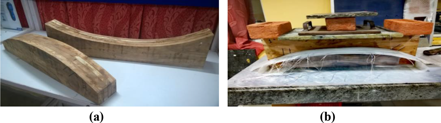
(a) Wooden pattern and (b) weight on the top of the composite-laminated spring.
The composite-laminated spring is further trimmed with a hand cutter to achieve the required dimensions. Figure 2(a) shows the C-glass-reinforced composite-laminated springs. At the center of the leaf springs, a hole is made using a drilling machine to attach with the master leaf spring. Figure 2(b) shows the drilled glass fiber–reinforced composite-laminated spring. The glass composite graduated leaf springs are attached with the master leaf spring using a central bolt. Figure 2(c) shows the assembly of the composite-laminated spring.

(a) Glass fiber composite graduated leaf spring, (b) drill in glass fiber composite graduated spring, and (c) assembly of laminated springs.
Characterization
Flexural test
A three-point bend test was carried out to determine the mechanical property of the glass fiber composite specimen, as shown in Figure 3. A specimen made up of 10 layers of C-glass fiber of 440 mm length and 50 mm width is tested in an HEICO universal testing machine having 400 KN capacities as per the ASTM standard. The support span of the specimen is 400 mm, and the feed rate to the specimen is 0.1 KN/s. The specimen is placed at the rollers so that it behaves like a simply supported beam.
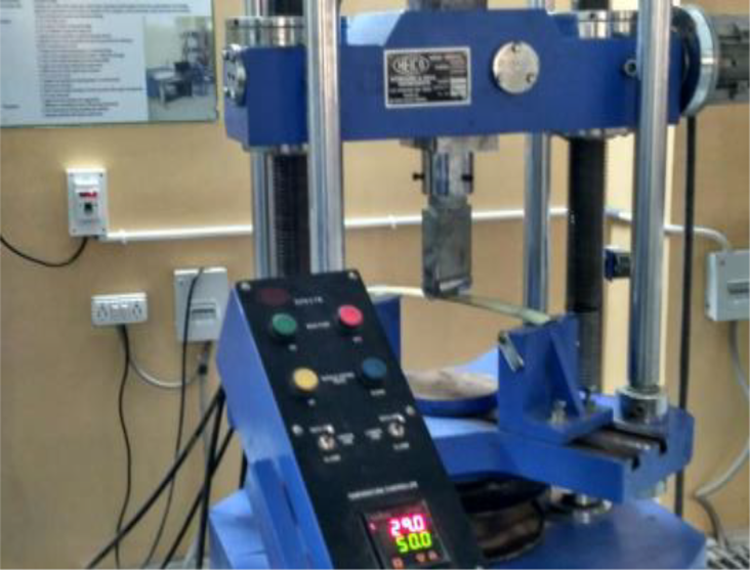
Three-point bend test.
Tap test
The nondestructive test (tap test), as shown in Figure 4, is conducted to determine the modulus of the glass fiber composite specimen. The specimen of dimension 290 mm length and 30 mm width is cut, where the thickness of a ply is 0.4 mm and a gauge length of 260 mm is maintained. From Euler’s beam equation (1), the mechanical property of the glass fiber composite specimen is obtained. The first modal natural frequency of the composite specimen is 28.9 Hz, as shown in Figure 5
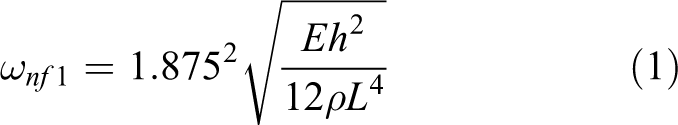
where E = Young’s modulus of elasticity, h = thickness of the specimen, ρ = density of the specimen, L = length of the specimen, and
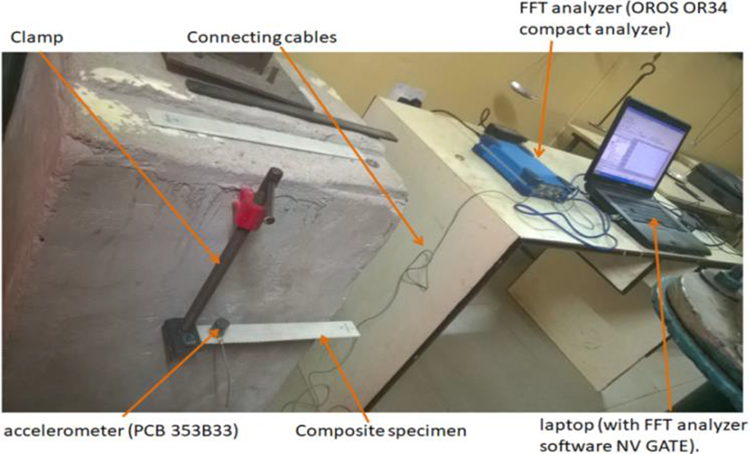
Tap test.

First modal natural frequency of C-glass composite specimen.
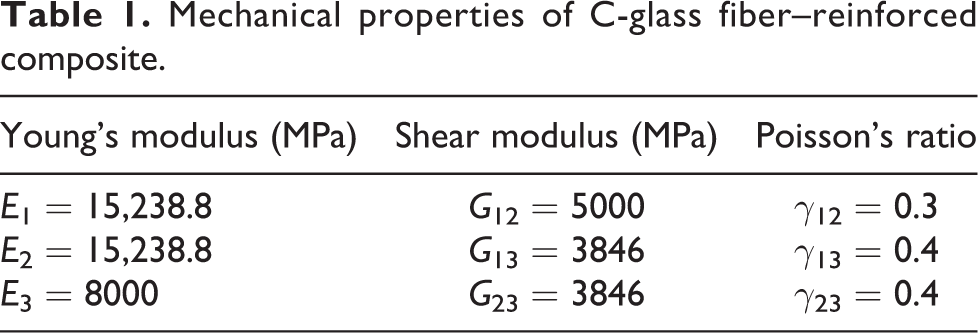
Mechanical properties of C-glass fiber–reinforced composite.
Design of laminated spring
The laminated spring is designed for achieving a lightweight vehicle having wheel base (b) = 2000 mm, wheel track = 1100 mm, center of gravity of vehicle from the ground (h) = 700 mm, center of gravity from rear wheel (a) = 1000 mm, maximum mass of vehicle (w) = 5886 N, maximum turning angle (Φ) = 30°, diameter of tire = 500 mm, and factor of safety = 2. Maximum load on a wheel = (maximum weight of car × gravity × FOS)/4 Maximum load on a wheel = 2943 N. Vertical load due to bump = R × 4.5 Maximum force generated due to bump = 13,243.5 N. Bending stress induced in full-length leaves
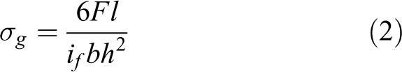
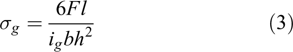
Bending stress induced in graduated leaves
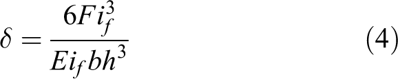
Deflection in full-length leaves
Deflection in graduated leaf spring
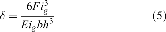
where L = length of the master leaf (eye to eye), l = half-length of the master leaf, F = force (in Newton), b = width of leaf spring, h = thickness of leaf spring, if = number of full-length leaves, and in = number of graduated leaves. The maximum allowable stress taken to design the steel leaf spring is 450 MPa. From equations (2) –(5), the thickness (h) is 24.71 mm and a deflection of 19.681 mm of the mono steel leaf spring is obtained.
Optimization of laminated spring
ANSYS is used to optimize the weight, deflection, and load-carrying capacity of laminated leaf spring for the light weight electric vehicle. The steel leaf spring is modeled using CREO and then imported in ANSYS. The ANSYS composite pre–post module is used to model the composite-laminated spring. In the ACP module, the material property of the C-glass composite is inserted into the engineering data. The surface of the composite-laminated spring is modeled in a geometry workspace of 830 mm length for master leaf and required lengths of the graduated leaves having a 60 mm width of all springs. The camber of the composite spring is the same as the camber of steel-laminated spring. The laminated spring surface meshes use a brick element with 540 nodes and 445 elements for an 830-mm-long laminated spring, 528 nodes and 435 elements for a 700-mm-long laminated spring, and 375 nodes and 296 elements for a 500-mm-long laminated spring. The thickness of the C-glass fiber is 0.4 mm. The required number of layers is given for the laminated spring, and epoxy resin is used as a dropoff material. The different laminated springs are assembled in ANSYS workspace, and the static structural module is used to determine the deformation and von Mises stress in the laminated leaf spring. The different numbers of layers and different lengths of graduated laminated spring combination is assembled to obtain deformation and von Mises stress under the maximum bump load of 13,243.5 N.
Different lengths and numbers of layers are optimized using ANSYS. Table 2 shows the deflection and von Mises stress of different leaf lengths and numbers of layers combination of the laminated spring.
Deflection and von Mises stress of different leaf lengths and numbers of layers combination of the laminated spring.

Figure 6(a) and (b) shows the deformation and stress graph under the full bump load. The glass fiber–reinforced composite-laminated spring having a master leaf of length 830 mm, 50 layers of glass fiber, and two graduated leaves, one having 700 mm length and 35 glass fiber layers and the other having 500 mm length and 25 glass fiber layers is more optimized compared with other 15 glass fiber–laminated reinforced laminated spring. Under the full bump load 13,243.5 N, the optimized glass fiber–laminated spring shows a deformation of 36.674 mm with a von Mises stress of 164.8 MPa. The hand layup method is used to fabricate the laminated spring, but it is observed that during the time of manufacturing, the eye of the master leaf is difficult to fabricate with accurate dimension without any manufacturing defects. Thus, the eyes of the master leaf are difficult to fabricate so the steel master leaf is used instead of the composite master leaf.

(a) Deformation in different glass fiber composite–laminated spring and (b) stress in different glass fiber composite–laminated spring.
Boundary condition
The boundary condition is provided to the laminated spring such that it behaves like the real laminated spring in the suspension system. Figure 7 shows the glass fiber composite–laminated leaf spring: support 1 is the front support of the laminated leaf spring, and support 2 is the rear support of the laminated leaf spring. In the first support, the lateral motion along the x-axis, y-axis, and z-axis is restricted, rotation about the x-axis and z-axis is fixed, and only rotation is provided about the y-axis. In support 2, the lateral motion along the y-axis and z-axis is restricted, lateral motion is allowed in the x-axis, rotation about the x-axis and z-axis is fixed, and rotation is provided about the y-axis. The load is applied at the center of the composite-laminated spring in the negative z-axis. Figure 8 shows the deformation in a glass fiber composite–laminated springs under the full bump load.

Glass fiber composite–laminated spring.

Deformed composite-laminated spring.
Results and discussion
The non-destructive method, that is, tap test, is used to determine the first natural frequency of the C-glass fiber–reinforced composite beam. The obtained natural frequency is used in Euler’s beam equations to determine the 15,238.8 MPa modulus of glass fiber composite specimen. The three-point bend test is carried out in the glass fiber–reinforced composite specimen to determine and validate the modulus value obtained from the tap test. The modulus from three-point bend test is 15,467.13 MPa, and it is observed that the moduli obtained from both the tests are in good agreement. The obtained mechanical property of the C-glass fiber composite specimen is inserted in the engineering data, and the modal analysis (using ANSYS) is carried out to determine the natural frequency of the specimen. From the tap test, the natural frequencies of the specimen are 28.9 and 29.143 Hz from the analytical method. Figure 9 shows the first modal natural frequency of the composite specimen. The error percentage between the experimental and numerical values is 0.84%, which indicates that the natural frequencies obtained from both the tap test and ANSYS have good accuracy.

First modal natural frequency of composite specimen.
Flexural properties
A three-point bend test is carried out to determine the load versus deformation curve for steel master leaf and composite graduated leaf. Figure 10 shows the deformation versus load curve, and it is observed that at the 1600 N load, deformation in steel spring is 114.38 mm and deformation in composite spring is 55.73 mm. At the same load, the steel leaf spring deflects 50% more than the composite leaf spring. At the 1600 N load, the steel leaf spring becomes flat, so it is taken as the maximum experimental load.
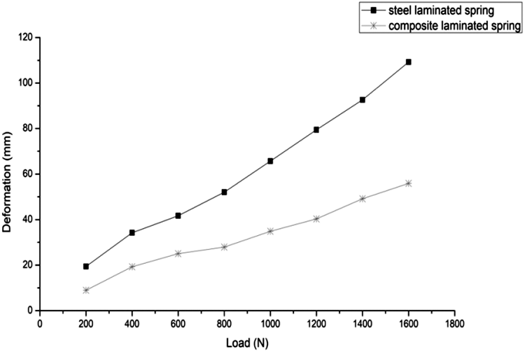
Deformation versus load curve.
Figure 11 shows the stress versus load curve of both springs, from which it is observed that the stress induced in steel spring is more than that in composite spring at the same load. Figure 12 shows the load versus deformation curve of composite-laminated spring between experimental and numerical methods, and it is observed that the composite-laminated spring deforms linearly under the applied loading conditions. The experimental results are in good agreement with the numerical results, which indicates that ANSYS is a suitable tool to optimize the composite structures.
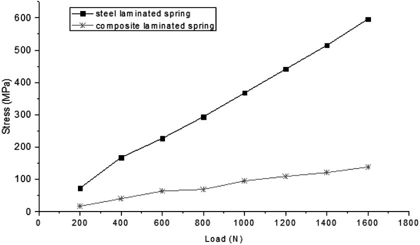
Stress versus load curve.
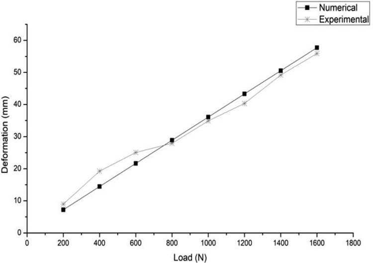
Load versus deformation curve of composite-laminated spring between experimental and numerical methods.
Vibration analysis
The vibration test is carried out to determine both the damping property of the laminated spring and the acceleration induced at a different velocity of the vehicle. The accelerometer MPU6050 is used to determine the acceleration, and it is connected with the Arduino circuit, which in turn is connected with a laptop through a connecting cable. The Arduino IDE software is installed in the laptop, which gives the acceleration versus time data. Figure 13(a) shows the MPU 6050 accelerometer and Arduino circuit, and Figure 13(b) shows the vibration setup in the electric vehicle.
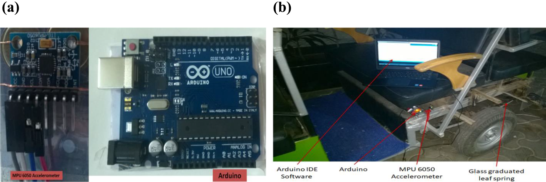
(a) MPU 6050 accelerometer and Arduino circuit and (b) electric vehicle for testing.
The accelerometer is placed at the chassis to obtain the acceleration produced in the vehicle chassis or body during the running of the vehicle. A known amount of load (735 N) is placed at the top portion of the rear axis and removed gradually, due to which the leaf spring of the vehicle gets deformed. After the removal of the external load, it regains its original shape and gets damped on its own. The damper is a mechanical element that is used to damp the vibration; hence, it is attached to a suspension system to reduce the vibration time. To determine the damping property of both composite- and steel-laminated spring, the damper is removed from the vehicle.
The damping property of the composite-laminated leaf is measured with and without damper, as shown in Figure 14: damping property of composite-laminated spring with damper (Figure 14(a)), damping property of composite-laminated spring without damper (Figure 14(b)), and damping property of steel-laminated spring without a damper (Figure 14(c)). It is observed from the following figures that due to the presence of a damper, the time required to damp the vibration is less because damper dissipates the energy in the form of friction and heat. Therefore, a comparison between the damping properties of the composite-laminated spring and steel-laminated spring is made in the absence of the damper. The laminated spring with composite graduated leaves takes less time than the steel-laminated spring to damp the vibration completely. The laminated spring with composite graduated leaves requires less time to damp the vibration, which means that the damping property of the suspension system increases with the use of composite in laminated spring.
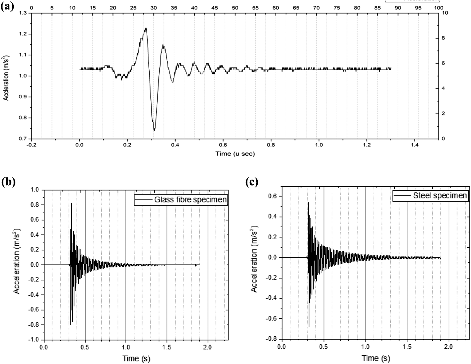
Damping property of (a) composite-laminated spring with damper, (b) composite-laminated spring without damper, and (c) steel-laminated spring without a damper.
At the constant speed of 20 m/s at the same road condition, the vibration induced in chassis is determined. Figure 15 shows the vibration induced in a vehicle with (a) composite-laminated spring and (b) steel-laminated spring. It is observed that when the composite graduated leaf spring is used in the suspension system, the acceleration reaches 1.3g (g = acceleration due to gravity) compared with the steel graduated leaf springs having 1.45g. The magnitude of acceleration is greater in steel-laminated spring, which indicates that steel-laminated spring transmits more forces to the chassis in comparison with glass-laminated spring.

Vibration induced in a vehicle with (a) composite-laminated spring and (b) steel-laminated spring.
Noise level of the laminated spring
Mechanical elements produce noise during their operating conditions. To check the noise with composite graduated leaf and steel graduated leaf spring used in suspension system, the Matrix+TM model SL-4005 sound-level meter as shown in Figure 16 is used. The noise induced by the laminated springs is obtained at night, as during that time, the environment noise is very minimal. Thus, the increased noise in the laminated spring after removal of the load can be easily detected. The noise readings are taken in three different frequency weighing scales “A,” “C,” and “F.” In the A-weighing scale, the frequency response of the meter is similar to the response of the human ear. A-weighing is commonly used for environmental or hearing conservation program such as OSHA regulatory testing and noise ordination law. C-weighing is a much flatter response and is suitable for the sound-level analysis of machines, engines, and so on, and F is a flat weighing scale. Lp (sound level) measuring parameter is used at fast response time, and the sound level is measured in decibels (dB).
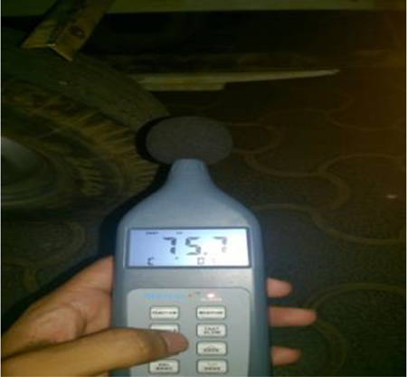
Matrix+TM model SL-4005 sound-level meter.
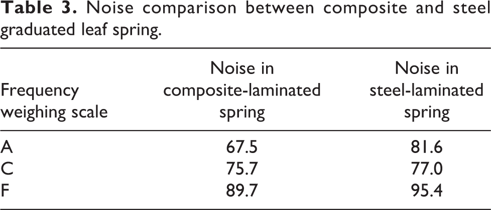
The surrounding noise during daytime is more than at nighttime. The noise level of the springs is taken during nighttime. Table 3 shows the noise levels of laminated springs in different frequency weighing scales, and it is observed that leaf spring with composite graduated leaf produces less noise in all three frequency weighing scales compared with the leaf spring with steel graduated spring.
Noise comparison between composite and steel graduated leaf spring.
Weight reduction
A digital weighing machine is used to determine the weight of laminated springs. Figure 17 shows the weight of a composite graduated spring of length 700 mm and 35 layers of glass fibers. The weight of the steel master leaf is 3.1 kg, full-length steel graduated leaf is 2.73 kg, steel graduated leaf of length 600 mm is 1.57 kg, composite graduated leaf of length 700 mm is 1.07 kg, and composite graduate leaf of length 500 mm is 0.37 kg. The total weight of the spring having steel graduated leaves is 7.4 kg, and weight of spring having composite graduated leaves is 4.47 kg. A weight of 2.93 kg is reduced when composite graduated leaves are used instead of steel leaves.
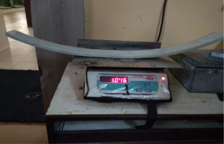
Weight of composite graduated spring of length 700 mm.
Natural frequency
The maximum frequency of the road irregularity is usually 12 Hz. 17 Therefore, to achieve a smooth ride, the suspension spring of the vehicle must have a higher natural frequency than the road irregularity frequency. Table 4 shows the comparison between mode shapes of spring having composite graduated leaves and spring having steel graduated leaves. First, six modal frequencies are obtained using ANSYS software. Table 5 shows the comparison between modal frequencies of a spring having composite graduated leaves and a spring having steel graduated leaves. The first modal frequency of spring having composite graduated leaves is 35.492 Hz, and that of the spring having steel graduated leaves is 28.835 Hz. In both the conditions, the natural frequency is higher than the road irregularity frequency and the spring having composite graduated leaves have a higher frequency than the steel graduated leaves, which provides better riding comfort to the passengers.
Comparison of mode shapes of spring with composite graduated leaves and spring with steel graduated leaves.
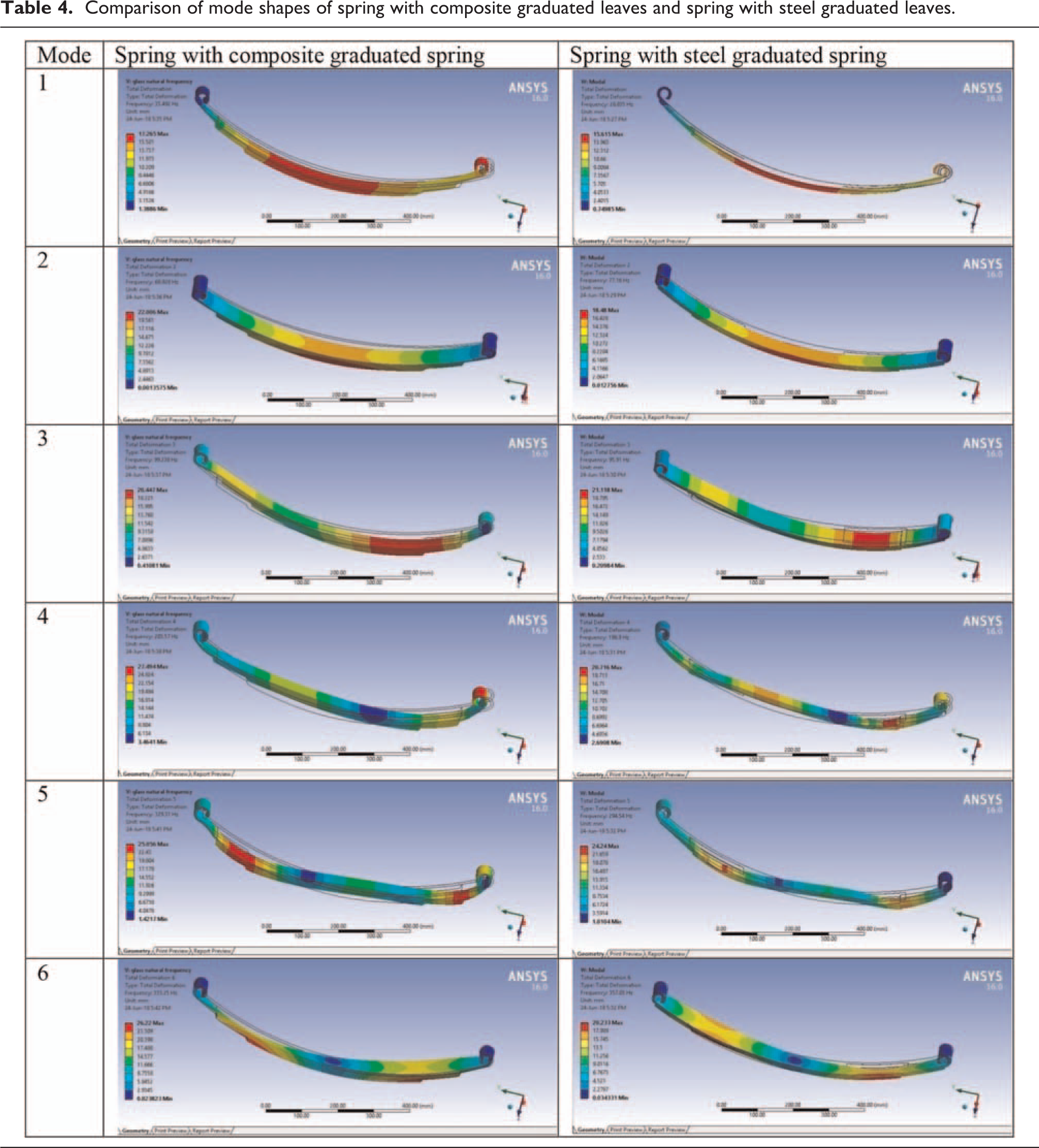
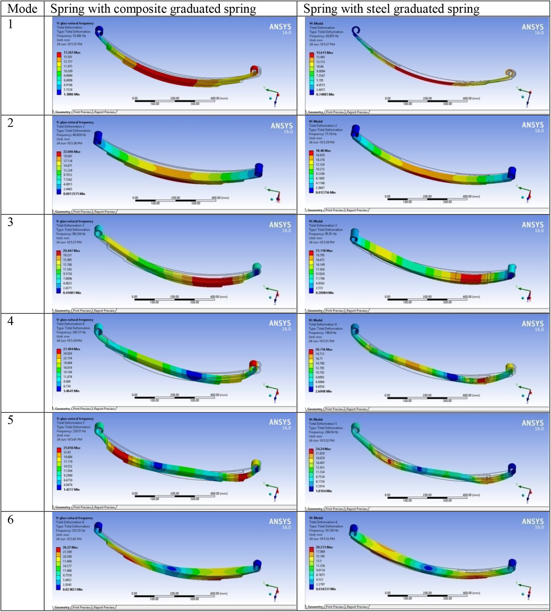
Comparison of modal frequencies of spring with composite graduated leaves and spring with steel graduated leaves.

Conclusion
Nowadays, electric vehicles are used instead of internal combustion engine as the latter possesses more weight, emits toxic gases that pollute air, produces noise pollution, and uses fossil fuels. ANSYS was used to optimize the laminated spring, and the optimized composite-laminated spring was fabricated and further experiments were conducted. The following conclusions may be drawn: Flexural test was carried out to validate the modulus obtained using the reverse calculation in Euler’s formula, and it was found that they were in good agreement with each other. The above test was also carried out to determine the load versus deflection curve and load versus stress curve, and it was observed that, at the same load, the deflection in steel-laminated spring is 50% higher than that of the composite spring and 76.39% more stress is induced in steel spring than composite spring. A higher reduction in weight (about 2.3 kg) of laminated spring was observed when composite graduated leaf was used, which can result in an increase in the efficiency of the vehicles. From the time versus acceleration curve, it was found that the time required to damp the vibration with composite-laminated spring was less compared with the steel graduated leaf spring, which indicates that the composite spring has a good damping property. The spring with composite graduated leaf has a higher natural frequency compared with the steel springs, which can be considered to provide better riding comfort to the passengers. Finally, it was found that the laminated spring with composite graduated leaf emits less noise than the steel leaf spring.
Footnotes
Declaration of conflicting interests
The author(s) declared no potential conflicts of interest with respect to the research, authorship, and/or publication of this article.
Funding
The author(s) received no financial support for the research, authorship, and/or publication of this article.