
Abstract
This article aims to determine the optimum parameters of a half-car model passive suspension vehicle passing on a random road. The optimum parameters are obtained based on the response of linear quadratic regulator control with a look-ahead preview for attaining the passive suspension performance nearly equivalent to the active suspension performance. The optimum parameters are estimated by equalizing mean square suspension controlling forces of passive and active vehicle models and subsequently minimizing the performance error between the two systems. The response of passive suspension with optimized parameters matches approximately with the active suspension response, with respect to ride comfort and road holding.
Keywords
Introduction
The dynamic behavior of the classical suspension system mainly depends on the spring and damper elements. The suspension system tries to suppress the effects of the uneven road disturbance on the output variables such as vehicle body acceleration, suspension space, and tire deflection. Passive suspension systems are not supported by any external energy source for any change in the stiffness and damping properties of the system, and in general, they are invariable. Because of the contradicting requirements and the fact that the vehicle has to operate in an extensive range of driving conditions, the choice of fixed stiffness and damping parameters must be compromised. 1 Because of the vast range of control forces in active systems, they may have better control over the vehicle dynamics and can give the best performance. However, this is paid in terms of very high energy requirements and in terms of system stability. 2 The main limitations of active systems are the difficulty in running control equipment, delay reaction, high costs, and comparatively less robust. In view of improving suspension performance, many researchers have been working on different control strategies.3–5
In fact, the introduction of energy into the active system can lead to unstable behavior if not properly controlled. Vehicles which require high performance need active controls, but this might be possible with high actuator power. It broadly identifies the fact that the active controls have constricted usage in general vehicles. 6 The passive suspensions are still used in most current production vehicles due to their low cost, reliability, and simplicity. Hence, stiffness of the suspension spring and coefficient of the damper are the two important design parameters, which should be selected properly for the passive suspension system.
Many researchers have been addressing the problem in view of improving the ride comfort and handling ability. Gobi and Mastinu 7 derived analytical formulae for describing the vehicle response to random excitation of road profile. They analyzed the parameter sensitivity with respect to different performance criteria. Using simplified vehicle models for optimization, the unwanted effects of the noise related to gradient information were reduced.8–9 Conservative optimization methods like pattern direction and reduced gradient technique exercise straight away on decision variables and may find only a relatively better solution but computationally expensive and may be inefficient. A quarter car test rig was established, and the suspension parameters were optimized for improved riding comfort under bump input. 10 The population-based optimization algorithms like genetic algorithm and teaching and learning–based optimization were used in passive suspension optimization successfully in view of ride comfort improvement. 11
In this article, a new optimization method has been used for optimization of half-car model passive suspension parameters based on a stochastic optimal controller. The stochastic optimal controller has been utilized as one of the best solutions for active suspension control. The preview control is used to realize the information related to the road profile that the moving vehicle runs into, and this information can be used for estimating the requisite control force more accurately. The benefits of preview control for better vehicle suspension performance in terms of driving quality, handling, and suspension space were widely studied and addressed in the literature.12–15
Kim et al. 16 have developed a road sensing system to improve the vehicle performance. They examined a preview scheme and evaluated the performance by simulation using the real data of the profile of test road through the road sensing system. Marzbanrad et al. studied the active control of a half-vehicle suspension model with a sensor affixed at its front for the preview information and also studied the case without the preview. They recognized that the preview information has improved performance of the control system and compensated for the system delays and actuator response. It was concluded that a short preview time is sufficient for control system performance improvement. 17 Rao and Narayanan optimized a skyhook damper–based semi-active vehicle suspension by using a new method of optimization. They showed that the skyhook damper suspension performance approaches the active suspension. 18 The preview information of the vehicle suspension dynamics is used in the active control of passenger seat and enhanced controllability of the active system. 19 The preview control combined with model following control method is applied to solve fault-tolerant control problems associated with a steam generator. 20 A predetermined feedback-based static preview controller 21 is used in the control of an aircraft model using preview data of wind velocity. The works presented in the field of active control of road vehicle vibrations showed that linear quadratic regulator (LQR) control is in good use with preview prospect.
Many of the works in passive vehicle suspension optimization considered ride comfort as objective function to be minimized and the other requirements as constraints. This work focuses on the possibility of increasing the performance of a passive suspension system to the level of optimal preview active suspension performance. A novel optimization method is used to obtain the optimal passive suspension parameters of a half-car model. The response statistics of any active control strategies can be taken as the reference, and passive suspension parameters can be optimized for obtaining the similar response of the active suspension. Thus, the new method provides design flexibility to obtain the desired performance of the passive suspension system matching with the performance of the active system.
Using the active scheme, the passive scheme is designed by modifying the weighting constants for obtaining the desired performance. The optimum values have been found out by equalizing the controlling forces of the passive suspension and the active suspension, in a mean square sense. The performance error between the two systems is minimized. From the results of this study, it is observed that the ride quality of the passive suspension can be raised in the level of an active suspension. Unlike other methods, the performance of the passive system at different driving speeds can easily be compared with the active system using this approach. It allows the designer to increase performance at the active level in the desired measure without strictly affecting other criteria. Thus, the proposed solution is a direct and effective approach for determining the optimal parameters and offers the designer a flexible environment.
Mathematical formulation
The vehicle models which are used in the analysis are discussed in this section. First, a half car with an LQR-preview controller passing over a random road is established. The road profile is incorporated into the dynamics of the entire system, so the problem can be viewed as a stochastic optimal control problem. The problem of active suspension optimization is solved for determining the control force that minimizes the cost function (J), which is as a weighted square sum of the control forces, tire deflections, wheel suspension travels, and bouncing and pitching accelerations. Next, a passive half-vehicle suspension model with the front and rear spring and damping elements is set, and the passive suspension control force is estimated.
Fully active suspension half-vehicle model using LQR control with a look-ahead preview passing through a random road
Figure 1 represents a half-vehicle model traveling on a random road with a velocity V. Fully active suspension half-vehicle model with look-ahead preview control.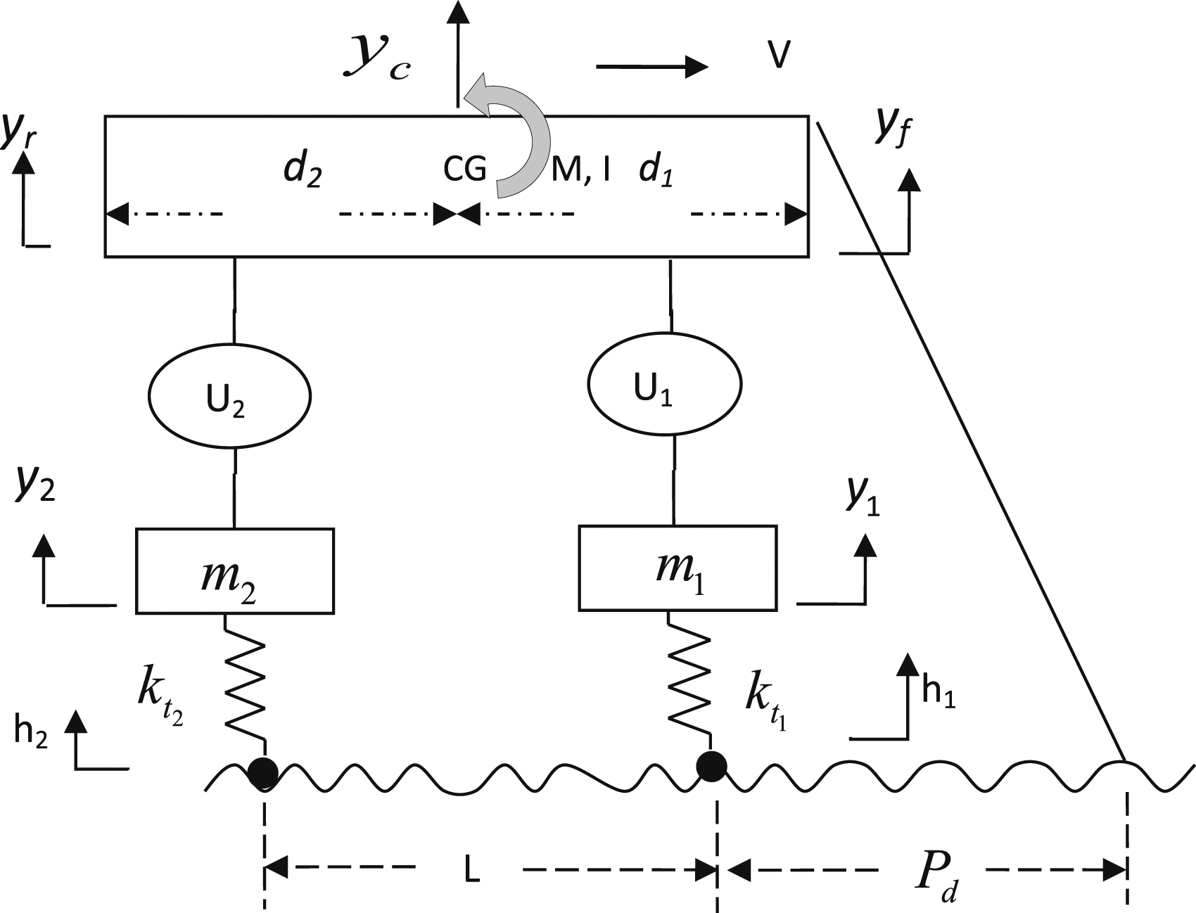
The LQR control scheme with preview can be used to minimize the specified performance index as a sum of the weighted mean-squared values of the response variables and the control force. This law is obtained as a function of assumed measurable state variables.
The control process is observable if every state can be identified by measuring the output over a finite-time interval. For state controllability in the controller, the state variables in the state vector need to be affected in such a way that the system reaches to a particular value within a finite amount of time by the control force.
A vertical plane separates the car in the longitudinal direction such that M is half of the mass of the vehicle body and I is half of the pitch moment of inertia along an axis of rotation across the center of gravity. The unsprung front and rear masses m
1
and m
2
relate to a single wheel, whereas


The road surface roughness can be approximated by using the formula
22
Some works in the literature in the area of active suspension design considered the road excitation as a component of a spatially homogenous random process which is considered as the output of a linear spatial shaping filter to white noise excitation. The linear spatial shaping filters have been chosen to be a first-, second-, or third-order filter to be representative of specific road conditions and to model the spectral density of the road profile as accurately as possible. In this article, the road input to the vehicle model is represented as the output of a first-order linear spatial shaping filter to white noise excitation.
The following equations represent the random road model
23


The action of the traverse of the vehicle over the road is embedded into the dynamics of the entire vehicle road system by inclusion of the road profile as a component of the state vector. This facilitates the formulation of the problem as a stochastic optimal control problem.
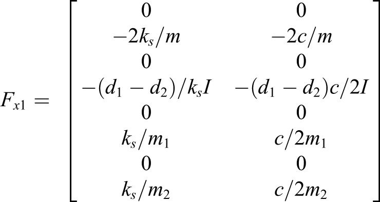
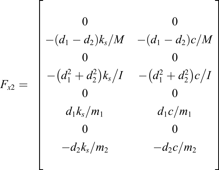
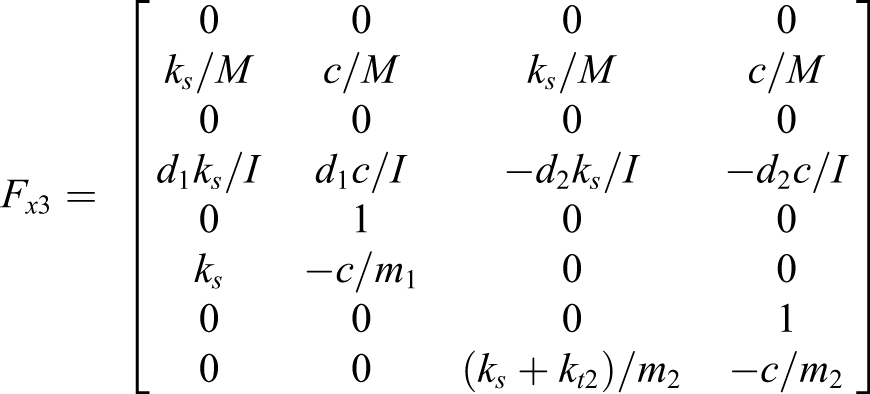
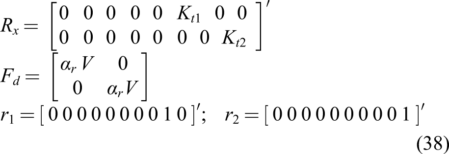
Combining the equations of (1)–(6), we get


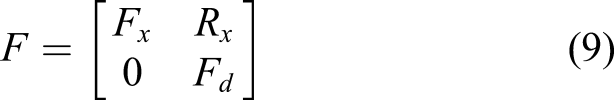
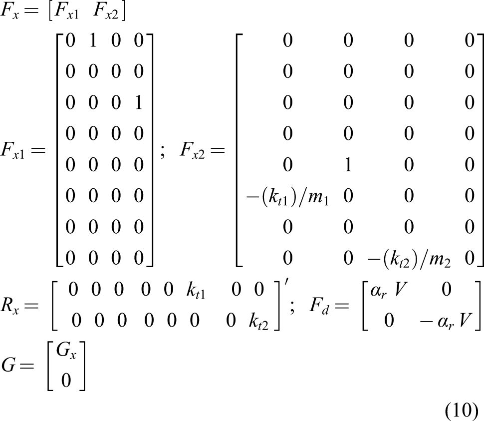
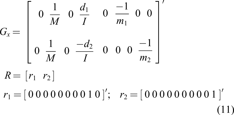
x(t), U(t), and w(t) represent the matrices corresponding to the system state, controlling force, and white noise vectors. They are given as follows


Performance index
The suspension problem aims at optimizing the system with reference to ride comfort, suspension stroke, and road holding. The ride comfort is measured by the mean square sprung mass bouncing acceleration
The overall performance index can be written as

Expressing equation (15) as

The performance index expressed by the above equation (15) can be put in the standard form as required for the application of linear stochastic optimal control theory.
Equation (16) is written as

Computation of preview control force and system state response
The road input information is assumed to be available through measurement at a preview distance of


Matrix S is solved by the Riccati equation


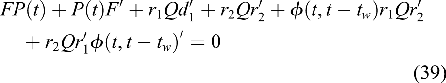
The optimal control force (U) represented by equation (17) is substituted in equation (7). Now, the system equation is written as

System response denoted by “P(t)” can be obtained by solving the Lyapunov equation


Passive suspension half-vehicle model under random road excitation
The equations of motion for the passive suspension half-vehicle model, shown in Figure 2, are written as follows Passive suspension half-vehicle model expected equivalent to the linear quadratic regulator-preview model.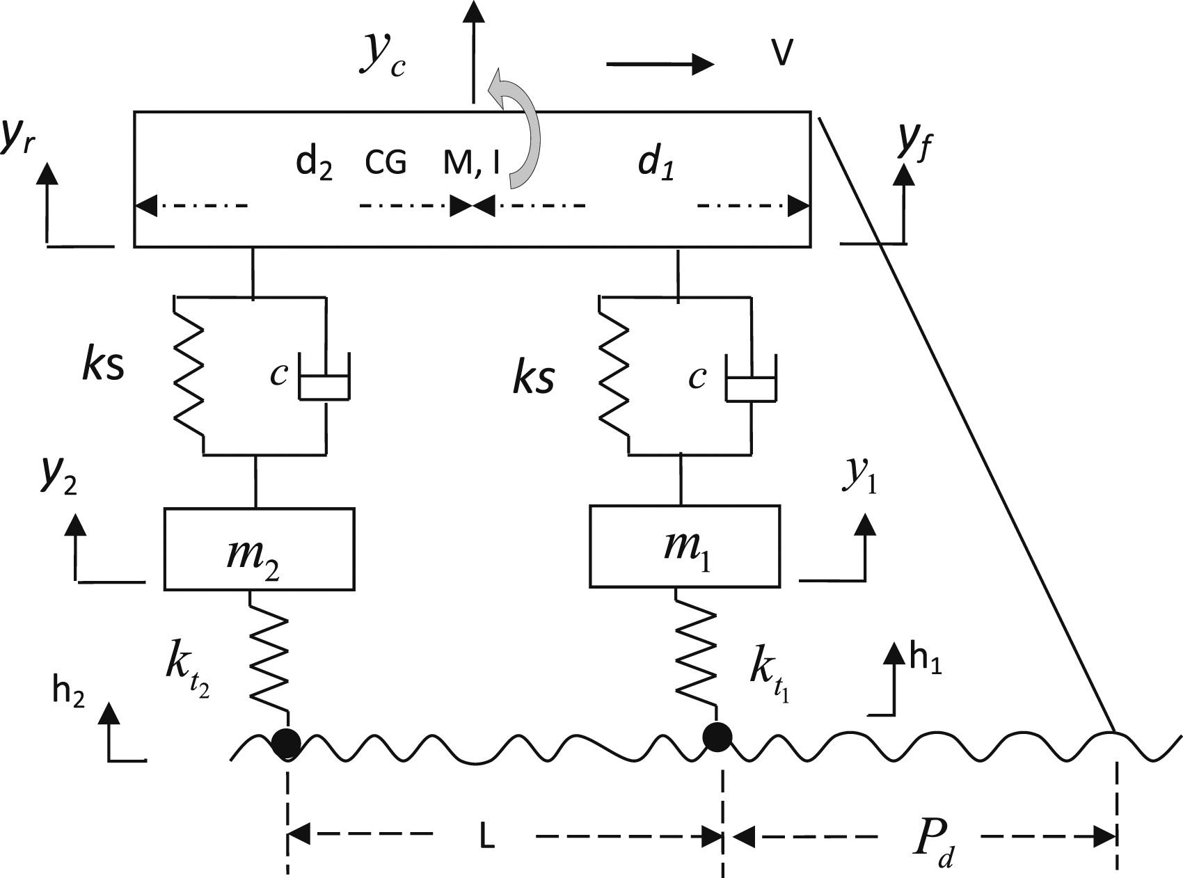
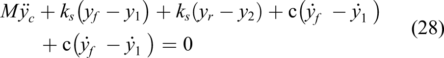

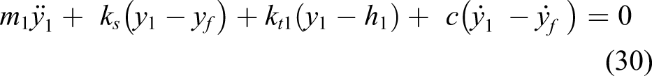
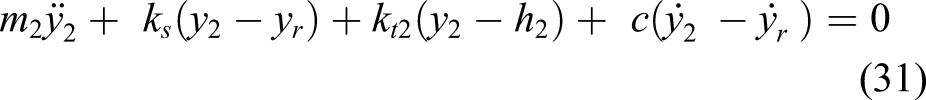


Equations (28) to (31) are represented by


The system response represented by the zero lag covariance matrix (P) is obtained by solving the Lyapunov equation given below
Optimization approach for half-vehicle passive suspension parameters
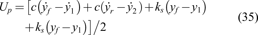
The passive suspension parameters
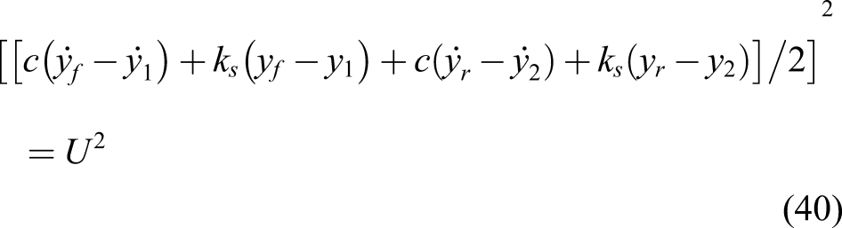
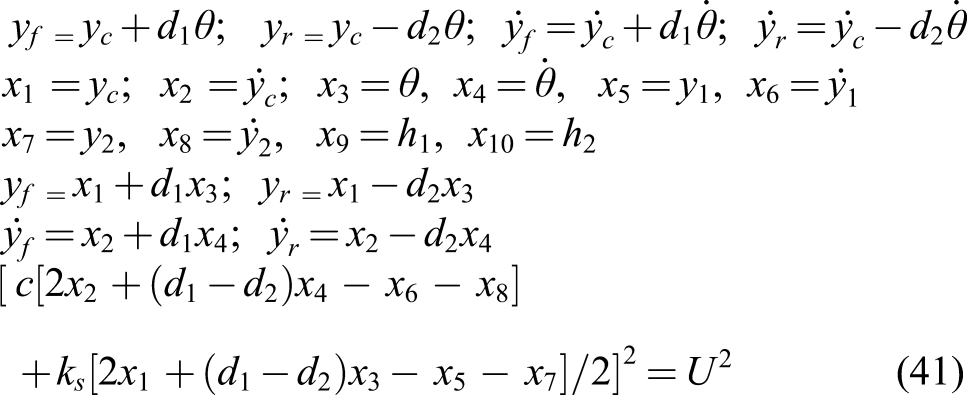
By equating the squares of equations (18) and (35), we get
For different
Consider the vehicle that travels with a speed of 15 m/s. The optimal solution for the half-vehicle model is produced using LQR control with preview. Using equation (18), the control force needed for the optimal response is computed. This control force is the reference force used for the optimization of passive suspension. The half-vehicle model suspension force term is taken from equation (35). To get the optimal response, the mean square suspension forces of both the schemes are made equal as given by equation (41).
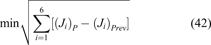
Fixing the
Results and discussion
Vehicle and road profile parameters.
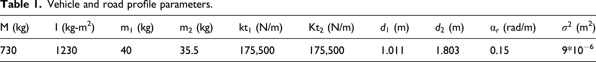
The weighing factors in the performance index are ρ1 = 1, ρ2 = 1, ρ3 = 106, ρ4 = 106, ρ5 = 106, ρ6 = 106, ρ7 = 10−4, and ρ8 = 10−4. The passive suspension optimal parameters are determined for better ride comfort and road holding using the optimization method discussed in the previous section. The optimal values in case of this example are
Figure 3 shows the overall performance of the active suspension at various preview distances varying with the velocity. Clearly, preview control provides higher performance than the non-preview control system. Overall performance of linear quadratic regulator-preview control system for different preview distances.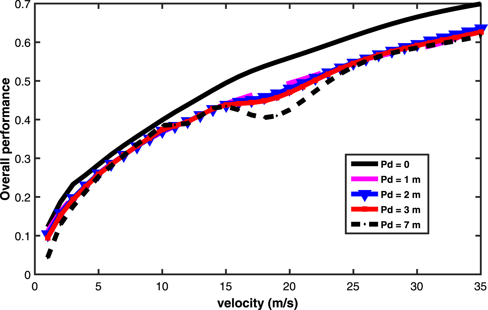
In case of higher speeds, preview control shows greater overall performance improvement. The effect of preview control at lower velocities is small. As the preview distance is increasing, the overall performance is improving. The specific benefit of the preview control has been utilized in passive suspension optimization. The optimum parameters have been found out by equalizing passive suspension controlling force and preview controlling force associated with the saturated preview length and further tuned to match with the preview system performance. Passive control suspension with the optimized parameters is intended to work similarly as an active system. Overall performance is improved with preview distance and is saturated after crossing the 2 m preview distance in this example. As a result, the active suspension control force and its response at a preview of 2 m is considered as a reference and used in the process of optimizing half-car suspension.
Figure 4 shows the variance of sprung mass bounce response with velocity. The active suspension response at 2m preview distance is plotted for comparing the bouncing acceleration of the passive suspension. In this criterion, the passive system response tracks closely with the active system response. At lower velocities below 5 m/s and at higher velocities above 25 m/s, there is a slight performance difference. The passive system performs as well as the active system and gives good ride comfort in the vertical direction at all speeds. Rms bounce acceleration response for optimal passive- and active-preview control systems.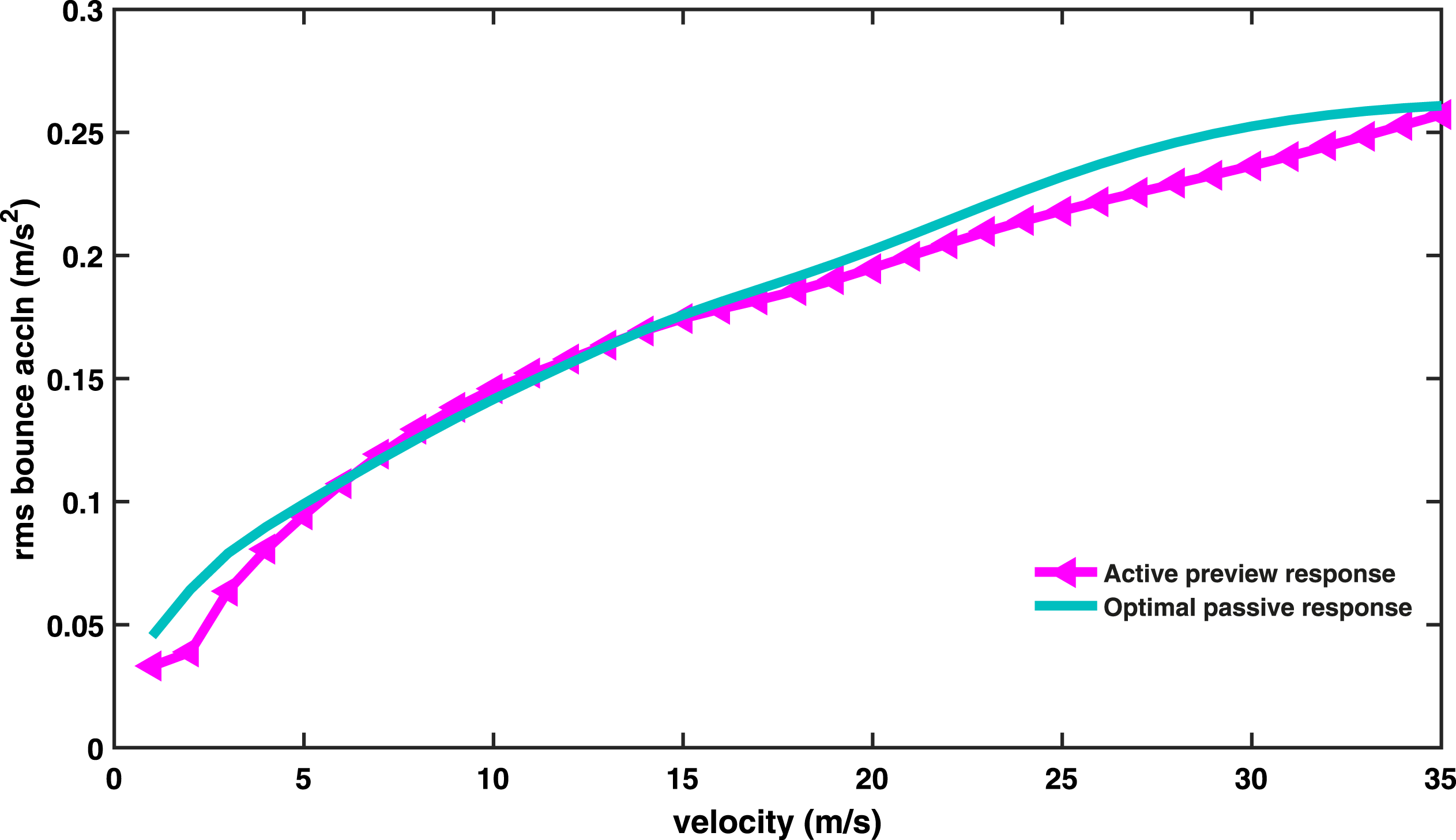
The pitching acceleration response of the optimized passive suspension is compared to the active system in Figure 5. The optimized passive suspension response is observed to be marginally better than the active system response. Rms pitch acceleration response for optimal passive- and active-preview control systems.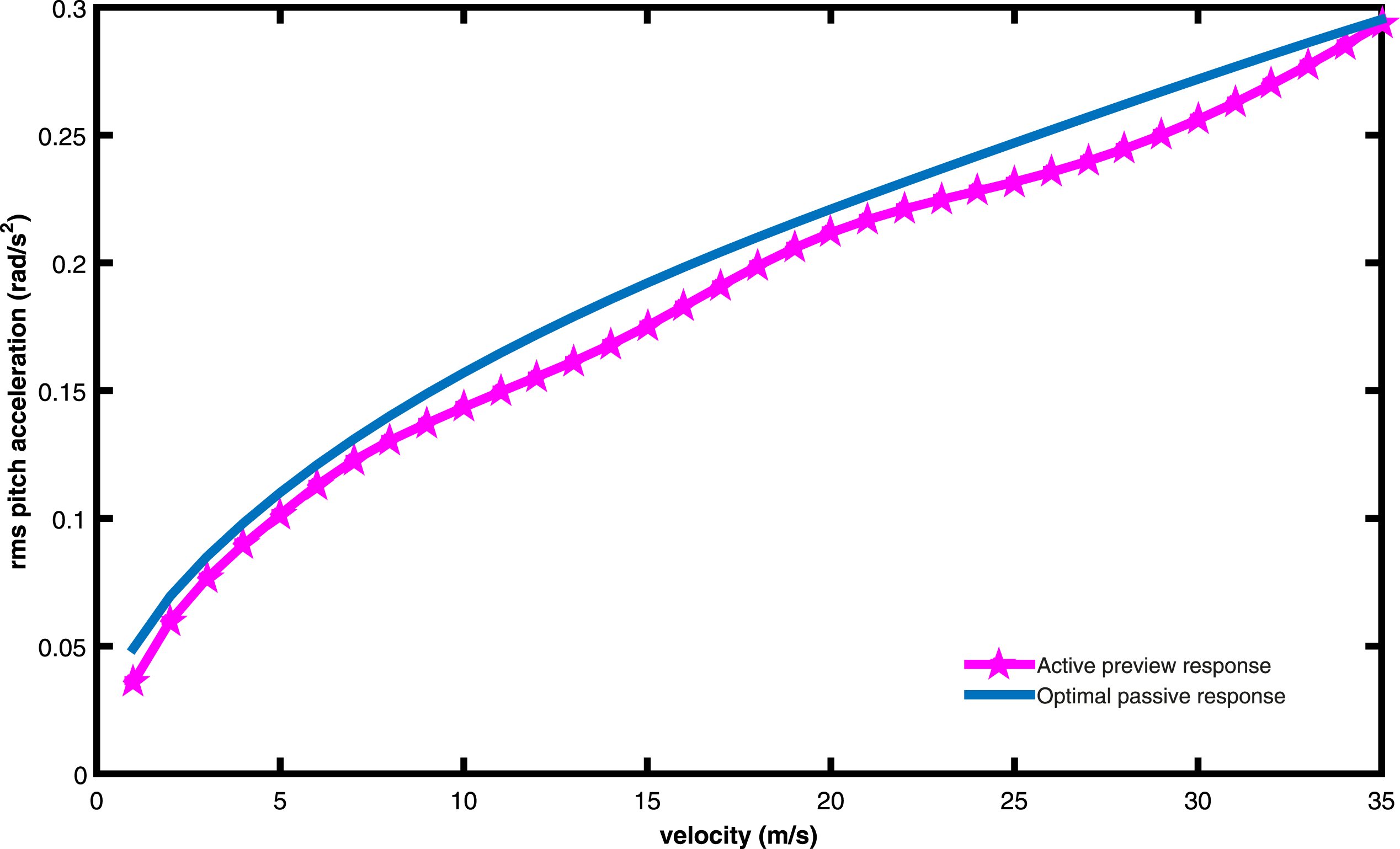
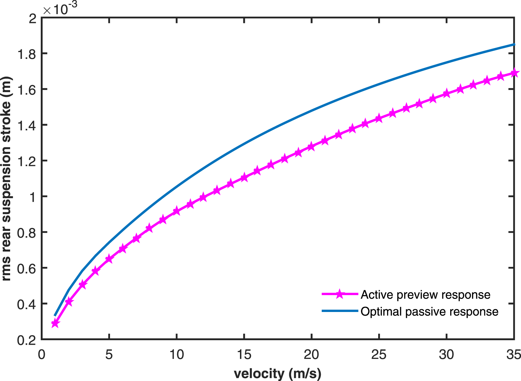
The suspension stroke responses of the optimum passive system are compared with the active system response and given in Figures 6 and 7. The passive front-wheel suspension stroke tracks the active system in all speeds. The performance in higher speeds is not closely matched. Similarly, the rear-wheel stroke is very similar to the active system at lower speeds up to 15 m/s. In case of higher speeds, the passive suspension performance in this respect is worse than the active system. Rms front suspension stroke response for optimal passive- and active-preview control systems. Rms rear suspension stroke response for optimal passive- and active-preview control systems.
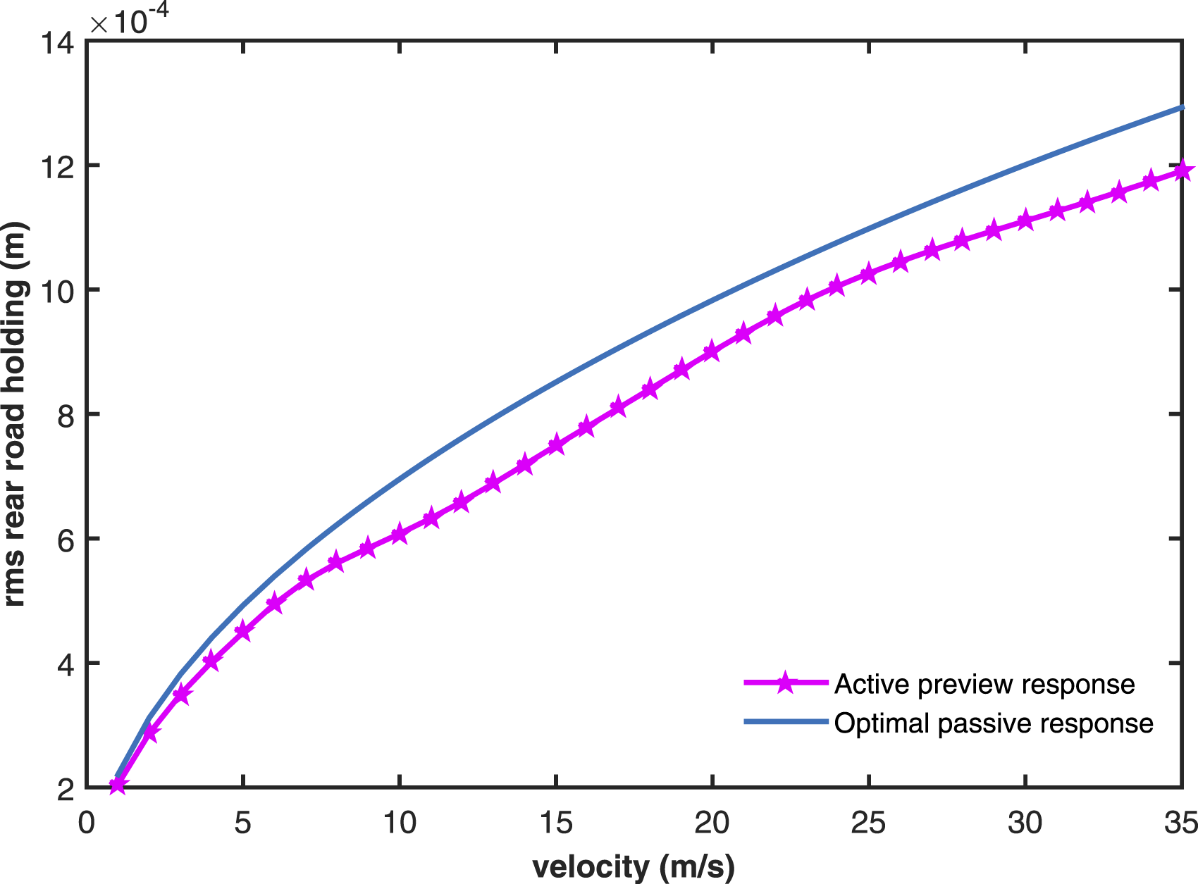
Figures 8 and 9 illustrate the response of the optimal passive and active systems to road holding. The passive system front-wheel road holding closely matches the active system at all speeds. The rear-wheel road holding also meets the active system at all speeds but demonstrates a somewhat poor response at higher speeds above 30 m/s. The results indicate that the passive suspension performance may be improved to the level of an active system performance. Rms front road holding response for optimal passive- and active-preview control systems. Rms rear road holding response for optimal passive- and active-preview control systems.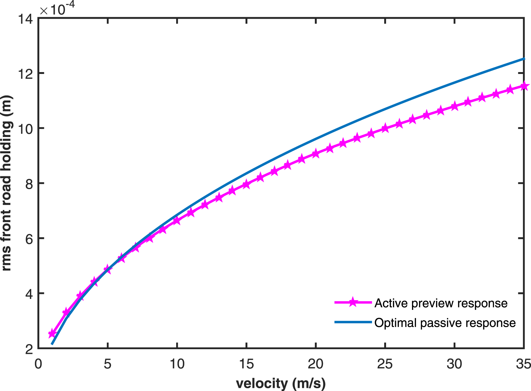
The performance of the passive system is very close to the performance of the active system at lower velocities. The passive suspension performance especially in respect of suspension stroke and road holding is little worse than the active suspension performance at higher speeds. The bounding values associated with the invariable passive suspension elements may be the reason for the mismatching performance between the passive suspension and active suspension systems at higher vehicle velocities.
This study focuses on design of a passive system that offers the best performance possible. The response of the passive system is compared with the LQR-preview active system to demonstrate the effectiveness of the optimization method. The ride quality is improved to the level of active suspension. The performance of the suspension stroke is limited but maintained in acceptable range. The results of this study support the proposed approach for effectively optimizing the passive suspension parameters. This approach can also be applied to improve the vibration control of machines to a desired performance flexible to the system specification.
Conclusions
In the passive suspension improvement, a half-car model that travels on a random road is investigated. An effective approach is used to determine the optimum parameters with an expectation of response of the passive suspension equivalent to the active suspension system. The optimum parameters are obtained by equating the corresponding rms control forces of the passive suspension and active suspension. The error of the sum of rms values related to the passive suspension and look-ahead preview active suspension in respect of bouncing acceleration, pitching acceleration, front and rear suspension strokes, and road holding is minimized. The optimized passive suspension performance has been brought as close to the performance of active suspension as possible.
Footnotes
Declaration of conflicting interests
The author(s) declared no potential conflicts of interest with respect to the research, authorship, and/or publication of this article.
Funding
The author(s) received no financial support for the research, authorship, and/or publication of this article.