



Abstract
Tuned-mass-dampers are extensively used in physical systems in order to reduce the dynamic response of the primary structures. The damping in a tuned-mass-damper system plays a significant role. In many engineering systems, we see damping is hysteretic in nature. Tuned-mass systems with nonlinear hysteretic damping are mathematically challenging. In this paper, tuned mass systems with rate-independent hysteresis are studied. In particular, first we study tuned mass systems with the famous Bouc-Wen model, and then we study tuned mass systems with the Bouc-Wen model and a recently developed scalar hysteresis model in parallel. Numerical approaches are used to study the dynamic responses of the systems. The sine sweep responses show two resonance peaks. The sine sweep responses indicate the amplitude versus frequency of the systems. The numerical results obtained for two different hysteretic dampers are compared.
Introduction
Tuned mass dampers (TMD) are often used in practical systems in order to reduce the high amplitude vibrations during operations. Usually, a secondary mass-spring-damper system is attached to the primary system to reduce the vibration amplitude. In TMDs, damping plays a very significant role in order to dissipate the energy of the structures. Figure 1 shows a simple TMD system with a linear viscous damper. Here, m1 is the mass of the primary structure supported by the spring k1; and m2 is the mass of the secondary structure that is attached to the primary mass by means of the spring k2 and the viscous damper c. Here, F0 sin ωt is the harmonic forcing input to the primary system. The use of the secondary mass-spring-damper system reduces the vibration amplitude of the primary mass m1. A tuned mass system with a viscous damper.
The concept of the TMD was developed more than a century ago. In 1909, Frahm 1 first developed the concept of TMD in order to reduce the rolling amplitude of ships. Den Hartog and Ormondroyd 2 developed a theory of TMD in 1928. In 1940, Den Hartog 3 analytically studied the optimal design of TMD. Since then there have been extensive researches on TMDs and their applications to real life engineering problems.
In the literature, TMD devices have been extensively used for vibration control. Here we refer a few review papers that extensively discuss the use of TMDs for vibration control. In Ref. [4], a state-of-the-art review is presented on behavior of base-isolated buildings to seismic excitation. The paper discusses in detail the theoretical aspects of seismic isolation and parametric behavior of base-isolated buildings. In Ref. [5], four types of TMDs are discussed, namely, conventional TMDs, pendulum TMDs, bi-directional TMDs and tuned liquid column dampers. In Ref. [6], recent developments in vibration control of structures using passive tuned mass dampers have been discussed. In particular, the paper discusses the response control of structures that are excited by wind and earthquake. In Ref. [7], a review is presented on several numerical techniques used for vibration control using TMDs.
The applications of TMDs include long span cable bridges, tall buildings and tall water tanks. In Ref. [8], the authors studied tuned mass damper for steel tower structures under winds and earthquakes. In Ref. [9], the authors used a pounding tuned mass damper (PTMD) for vibration suppression of a submerged cylindrical pipe. The PTMD uses collisions of tuned mass with viscoelastic materials to dissipate the energy of primary structures. The paper presents an experimental verification of a submerged PTMD system for underwater pipes. In Ref. [10], the authors studied control performance of active-passive composite tuned mass damper. The the active-passive TMD device is used to reduce the response of tall buildings under random excitations. In Ref. [11], the authors studied nonlinear vibrations of shallow cables with semi-active tuned mass damper. In the paper, the control device is a TMD with a variable out-of-plane inclination. A control algorithm is developed to regulate the inclination of the device and the vibration of cables. In Ref. [12], the authors studied active tuned mass damper for damping of offshore wind turbine vibrations. In the paper, the actuator force is controlled by the feedback from the tower displacement. In Ref. [13], the authors presented a review on dynamic analysis of tuned mass damper for tall steel structures. In Ref. [14], the authors studied the effects of a passive tuned mass damper on blade root impacts during the offshore mating process. In the paper, the authors studied the effects of TMD on the impact velocities between the blade root and hub. The authors found that the TMD can reduce the impact velocities by 40%.
As noted, the damper of the TMD device plays a very important role in reducing the amplitude of the primary structure. There are several papers available in the literature that consider viscous type of damping in the model. Both linear and nonlinear viscous dampers are used in the TMD systems.15–18 We note that the TMD systems with linear viscous damping are often analytically tractable. On the contrary, TMD systems with nonlinear damping models are mathematically challenging and analytical solutions are difficult to obtain. We note that TMD systems with nonlinear damping have slight degradation in control performance.
Here, we note that in many engineering systems, energy dissipation occurs in the form of rate-independent hysteresis. In general, rate-independent hysteresis introduces signum nonlinearities in systems. In the literature, several researchers used frictional damping in the TMD systems.19–22 In Ref. [23], a hysteretic tuned mass damper is used for structural vibration reduction. In Ref. [24], the Bouc-Wen hysteresis model25,26 is used as the damper in the TMD.
With the above motivation, in this paper we first study the TMD system with the Bouc-Wen model, and subsequently, the TMD system with the Bouc-Wen model and a rate independent scalar hysteresis model developed in Ref. [27]. The hysteresis model of [27] is motivated by a study of an elastic plate with several frictional microcracks. A specialty of the hysteresis model of 27 is that the resulting hysteresis loops show pinch at the origin, as the residual stress in the system was considered to be zero. Note that residual stresses leads to plastic deformation, warping and distortion of objects.
The Bouc-Wen hyteresis model and the hysteresis model of
27
are briefly discussed below. The Bouc-Wen hysteresis model is given by (a) A typical response of the Bouc-Wen model. Parameters used: A = 1, β = 0.85, γ = 0.32 and n = 1. (b) A typical response of the hysteresis model of.
27
Parameters used: κ = 4, θ
a
= 2, β0 = 1.8 and ϵ = 10−6. Here, f(t) = θ(t)z(t). (c) A typical response of the hysteresis model combined with both the Bouc-Wen model and the hysteresis model of.
27
Here, the same hysteresis model parameters are used as in cases (a) and (b), for the Bouc-Wen model and the hysteresis model of,
27
respectively. The output force f(t) is the sum of hysteretic output of two models. The input u(t) = sin 2πt is used for all three cases.

The rate-independent scalar hysteresis model of
27
is given by


Figure 2(b) shows a typical response of the rate-independent scalar hysteresis model of. 27 Note that the hysteresis loop is pinched at the origin.
Figure 2(c) shows a typical response of the combination of the Bouc-Wen model and the hysteresis model of. 27 Here, the hysteretic output is the sum of outputs of the two models. The hysteresis loop shows an interesting feature that the pinch at the origin has opened up due to the influence of the Bouc-Wen model. In some engineering materials with microcracks, this may indicate hysteresis with nonzero residual stress.
As discussed above, we first use the Bouc-Wen hysteresis model to study TMD systems. Subsequently, we use the Bouc-Wen model and the scalar hysteresis model of 27 in parallel in TMD systems. We compare the numerical results obtained for both cases.
Tuned mass systems with hysteresis
We first use the Bouc-Wen model as the hysteretic damper in the TMD system. Then, we use the Bouc-Wen model and the scalar hysteresis model of 27 in parallel in the TMD system. We discuss the governing equations of motions of the two systems and their responses below.
TMD with the Bouc-Wen hysteresis
A TMD system with the Bouc-Wen hysteresis is shown in Figure 3. Here, m1 is the mass of the primary system, k1 is the stiffness of the spring on which m1 is mounted, m2 is the mass of the secondary structure which is attached to the primary mass with a spring of stiffness k2 and a Bouc-Wen hysteretic damper indicated by h(t). A harmonic force F0 sin ωt is applied to the primary mass. A tuned mass system with the Bouc-Wen hysteresis.
Equations of motion of the system are given by


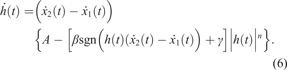
In equations (4) and (5), α is a scalar parameter that controls the level of damping. Note that the right hand side of equation (5) is 0, since no external force is applied to the mass m2.
TMD with the Bouc-Wen hysteresis and the other scalar hysteresis model in parallel
Figure 4 shows a TMD system with the Bouc-Wen hysteresis model and the hysteresis model of
27
in parallel.
27
Here, m1 is the mass of the primary system, k1 is the stiffness of the spring on which m1 is mounted, m2 is the mass of the secondary structure which is attached to the primary mass with a spring of stiffness k2 and two hysteretic dampers in parallel indicated by h1 and h2. Here, the damper h1 is governed by the hysteresis model of
27
, and the damper h2 is governed by the Bouc-Wen model. A harmonic force F0 sin ωt is applied to the primary mass. A tuned mass system with the Bouc-Wen hysteresis and the hysteresis model of
27
in parallel.
Equations of motion of the system are as follows



Here, h1 and h2 are derived as follows.
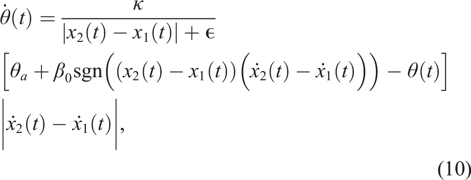


In equation (9), α1 and α2 are two scalar parameters that control the level of damping. Note that, the input displacement to the dampers is x2(t) − x1(t).
Numerical simulations
We first calculate the responses of the systems, given in Sections 2.1 and 2.2, for a fixed frequency. Next, we use a slowly time varying frequency to obtain nearly stationary responses. We use the Matlab function ode45 for all numerical integrations. Figure 5 shows the flow chart to perform the numerical simulations in Matlab using ode45. Flow chart for numerical simulations using Matlab function ode45.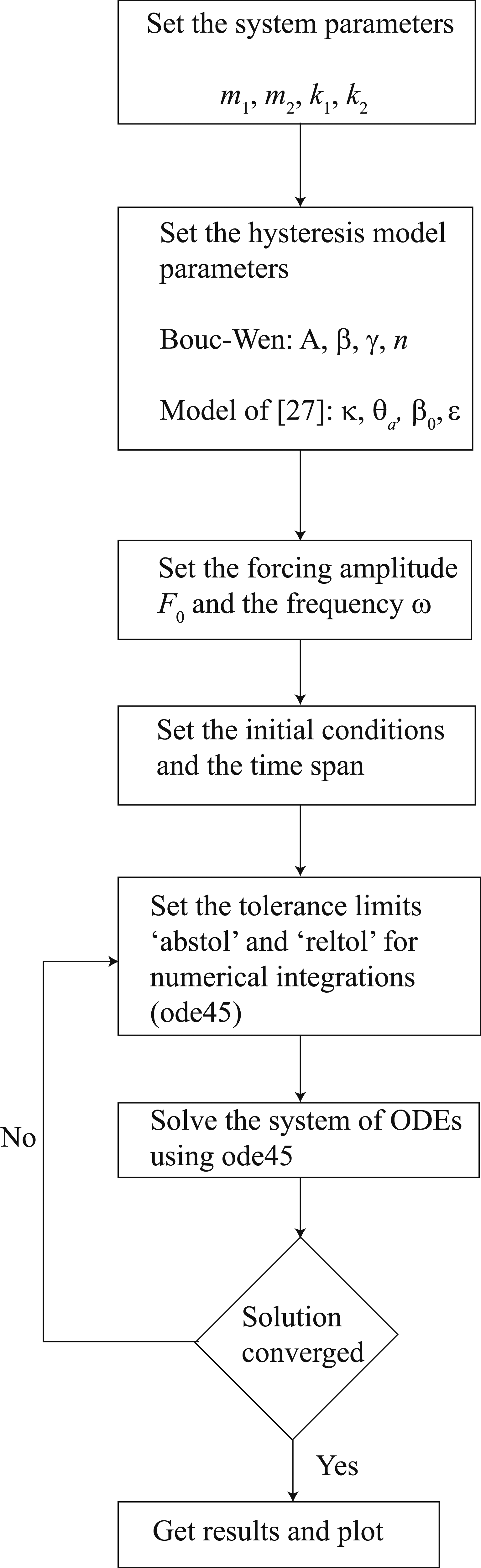
Steady state responses for fixed frequency

Figure 6 shows responses of the primary and secondary masses of the TMD with the Bouc-Wen model, for fixed forcing frequency. The responses show steady state behaviors after initial transients. Responses of the primary (left) and secondary (right) masses of the TMD with the Bouc-Wen model. Here, m1 = 1, m2 = 0.1, k1 = 1, k2 = 0.1, F0 = 1.2 and ω = 1.5. The Bouc-Wen model parameters used: A = 1, β = 0.5, γ = 0.1 and n = 1. The damping level α = 0.3.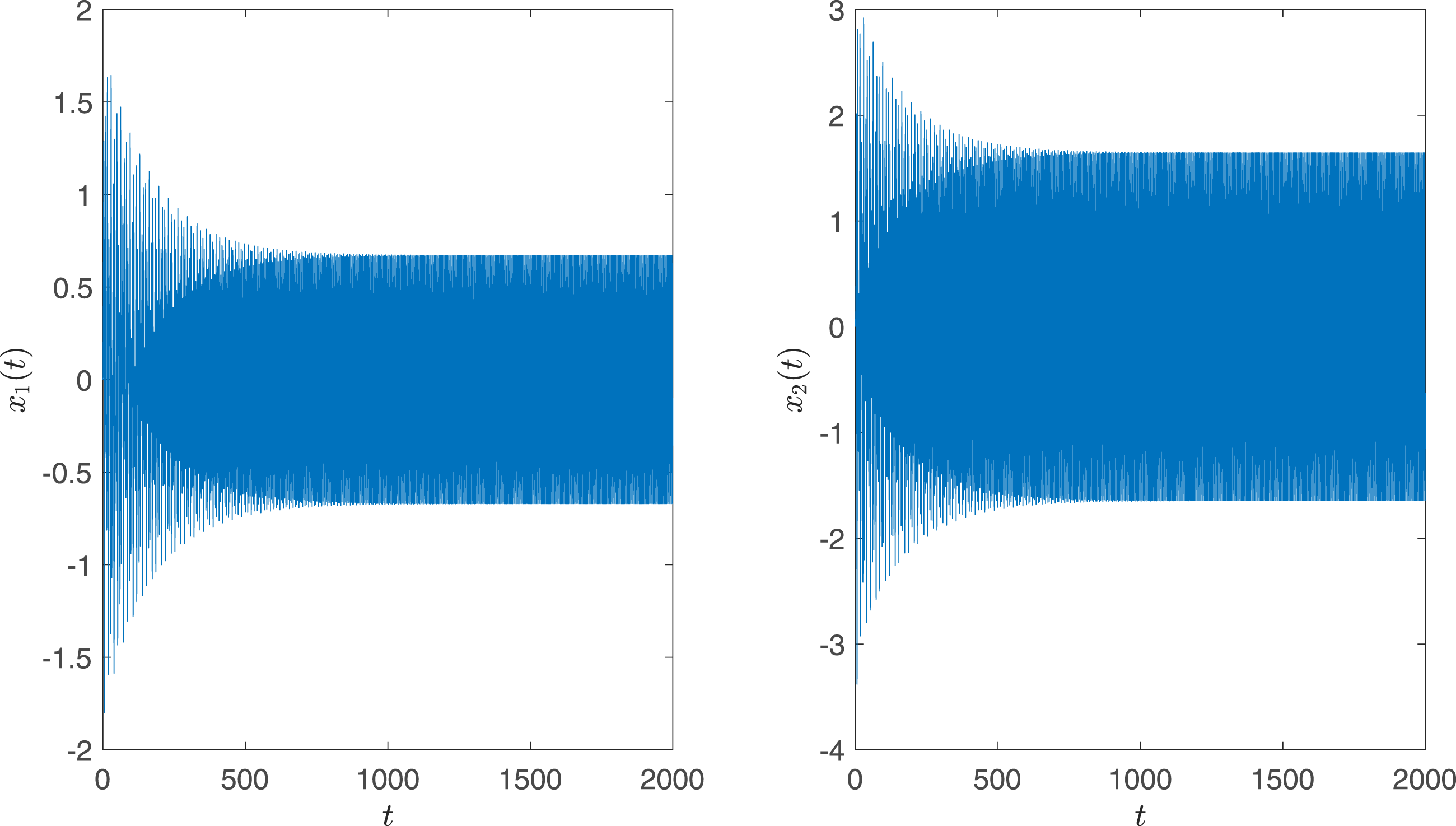
Figure 7 shows the corresponding plot of the hysteretic force αh(t) vs. the input displacement (x2(t) − x1(t)) to the damper. The hysteretic force αh(t) vs. the input (x2(t) − x1(t)) to the hysteretic damper.
Figure 8 shows responses of the primary and secondary masses of the TMD with the Bouc-Wen model and the hysteresis model of
27
in parallel, for fixed forcing frequency. Here also the responses show steady state behaviors after initial transients. Responses of the primary (left) and secondary (right) masses of the tuned mass dampers with the Bouc-Wen model and the hysteresis model of
27
in parallel. Here, m1 = 1, m2 = 0.1, k1 = 1, k2 = 0.1, F0 = 1.2 and ω = 1.5. The Bouc-Wen model parameters used: A = 1, β = 0.5, γ = 0.1 and n = 1. The other hysteresis model
27
parameters used: κ = 4, θ
a
= 2, β0 = 1.8 and ϵ = 10−6. The damping levels α1 = 0.1 and α2 = 0.05.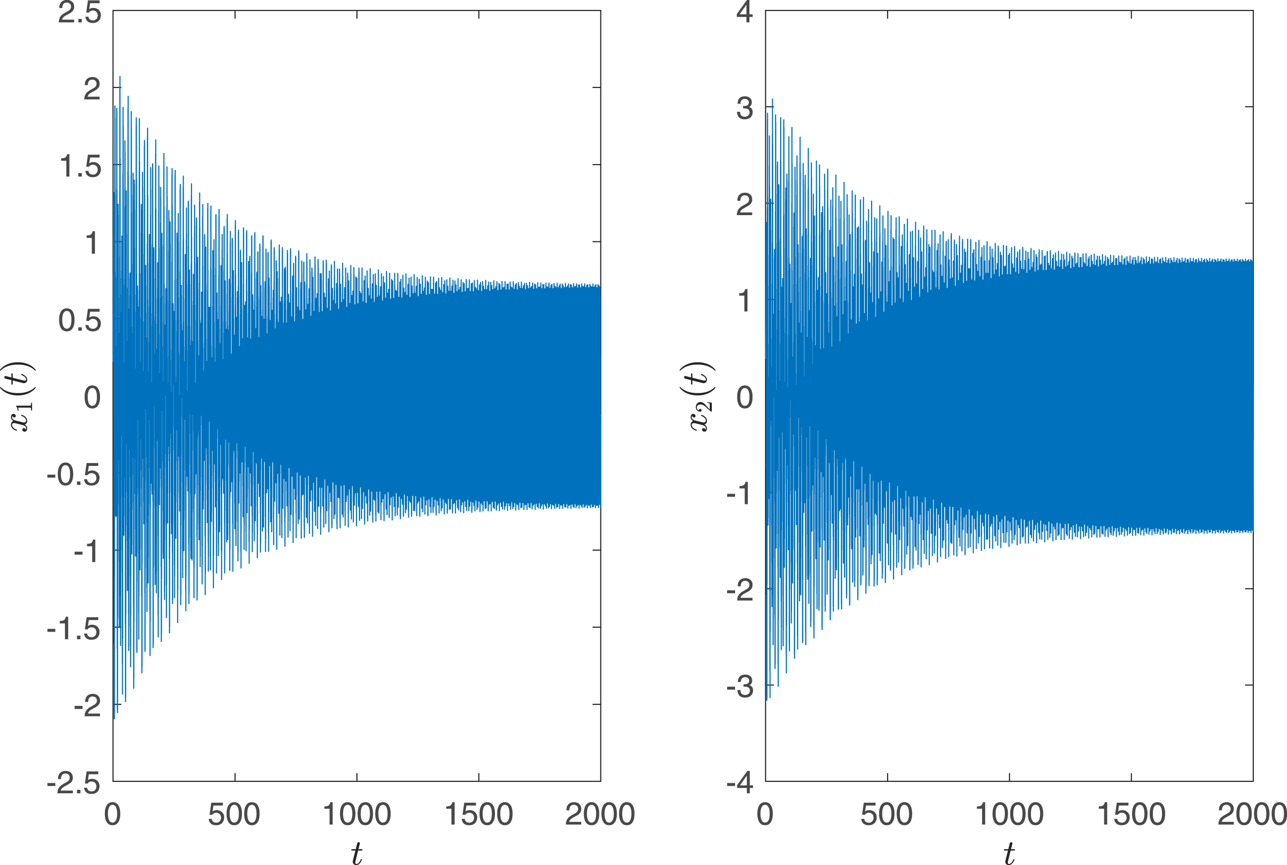
Figure 9 shows the corresponding plot of the hysteretic force α1h1(t) + α2h2(t) vs. the input displacement (x2(t) − x1(t)) to the dampers. The hysteretic force α1h1(t) + α2h2(t) vs. the input (x2(t) − x1(t)) to the hysteretic dampers in parallel.
Steady state responses for frequency sweep
We now use a slowly time varying frequency ω = 10−5t for the frequency sweep calculations. Note that with forcing F0 sin ωt, the effective frequency is
When a system is excited by a constant amplitude force with slow time-varying frequency (or sweeping frequency), and the frequency passes through the natural frequencies of the system, the response envelop captures the resonance peaks produced by sweeping excitation. In general, frequency sweeping produces an attenuated, broadened response peak. 28
For our computations, we consider the slow time-varying frequency to pass through the natural frequencies of the system so that the two resonance peaks can be captured. Figure 10(a) shows the frequency-sweep response of the primary mass for the TMD with the Bouc-Wen hysteresis. Similarly, Figure 10(b) shows the frequency sweep response of the primary mass for the TMD with the Bouc-Wen hysteresis and the hysteresis model of
27
in parallel. Resonance peaks are clearly observed in the frequency-sweep responses. The frequency-sweep responses of Figure 10 indicate the amplitude versus frequency of the primary mass. We can see the primary and secondary resonances of the TMDs. The two resonances occur near the two natural frequencies of the system. Between the two resonant frequencies, the amplitude decays drastically. This is consistent with the theory of vibration absorbers.
29
The resonant amplitudes and the resonant frequencies depend on the level of damping. If the level of damping is high, then the resonant amplitudes are low. By tuning the parameters of TMDs, we can control the resonant amplitudes of the systems. In future work, we will perform detailed quantitative analysis of parameter tuning. (a) Response of the TMD with the Bouc-Wen model. Parameters used: m1 = 1, m2 = 0.1, k1 = 1, k2 = 0.1, F0 = 1.2, A = 1, β = 0.3, γ = 0.1, n = 1 and α = 0.001. (b) Response of the TMD with the Bouc-Wen and the model of
27
in parallel. Parameters used: m1 = 1, m2 = 0.1, k1 = 1, k2 = 0.1, F0 = 1.2, A = 1, β = 0.5, γ = 0.1, n = 1, κ = 4, θ
a
= 2, β0 = 1.8, ϵ = 10−6, α1 = 0.01 and α2 = 0.01. TMD: Tuned mass dampers.
Figure 11 shows the amplitude versus frequency response of the primary mass of the system considered in Figure 10(b). Figure 11(a) shows |x1(t)| vs. ω
eff
. The red curve describes the amplitude versus frequency of the primary mass. Figure 11(b) separately shows the amplitude versus frequency of the primary mass. Amplitude versus frequency response of the system considered in Figure 10(b). (a) |x1(t)| vs. ω
eff
. The red curve describes the amplitude versus frequency of the primary mass. (b) Amplitude versus frequency of the primary mass.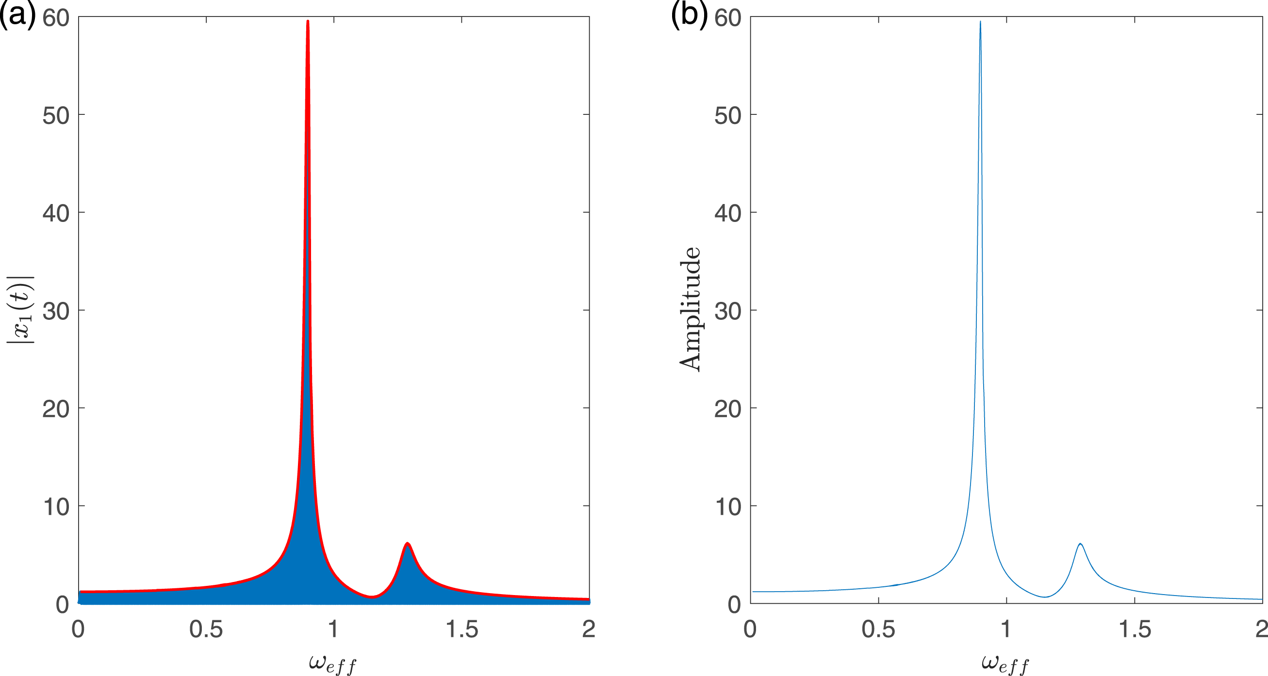
Results
In this section, we show frequency sweep responses for some cases of TMD with the Bouc-Wen hysteresis, and TMD with the Bouc-Wen hysteresis and the model of 27 in parallel. We consider different sets of hysteresis parameters to obtain frequency sweep responses. In Appendix A, we show some more results for the TMD with the Bouc-Wen hysteresis and the hysteresis model of 27 in parallel.
Figure 12 shows amplitude versus frequency captured through sine-sweep responses for four different cases. In all four cases, we consider the system parameters m1, m2, k1 and k2 to be the same. We vary the hysteresis model parameters in order to observe the changes in the resonant amplitudes due to damping. However, the precise understanding of the role of each hysteresis parameter requires a more detailed study. The same will be addressed in the future work in order to achieve greater quantitative understanding. Amplitude versus frequency response of the primary mass of the TMD. (a) and (b) TMD systems with the Bouc-Wen hysteresis model. (c) The amplitude versus frequency curves of (a) and (b) are compared. The blue curve corresponds to case (a) and the red curve corresponds to case (b). (d) and (e) TMD systems with the Bouc-Wen hysteresis and the hysteresis model of
27
in parallel. (f) The amplitude versus frequency curves of (d) and (e) are compared. The blue curve corresponds to case (d) and the red curve corresponds to case (e). We use m1 = 1, m2 = 0.1, k1 = 1, k2 = 0.1 and F0 = 1.2. We use slowly time varying frequency ω = 10−5t for all cases. Parameters used: (a) A = 1, β = 0.6, γ = 0.3, n = 1 and α = 0.03. (b) A = 1, β = 0.5, γ = 0.1, n = 1 and α = 0.03. (c) A = 1, β = 0.6, γ = 0.3, n = 1, κ = 4, θ
a
= 2, β0 = 1.8, ϵ = 10−6, α1 = 0.01 and α2 = 0.02. (d) A = 1, β = 0.5, γ = 0.1, n = 1, κ = 3, θ
a
= 1, β0 = 1.5, ϵ = 10−6, α1 = 0.05 and α2 = 0.03. TMD: Tuned mass dampers.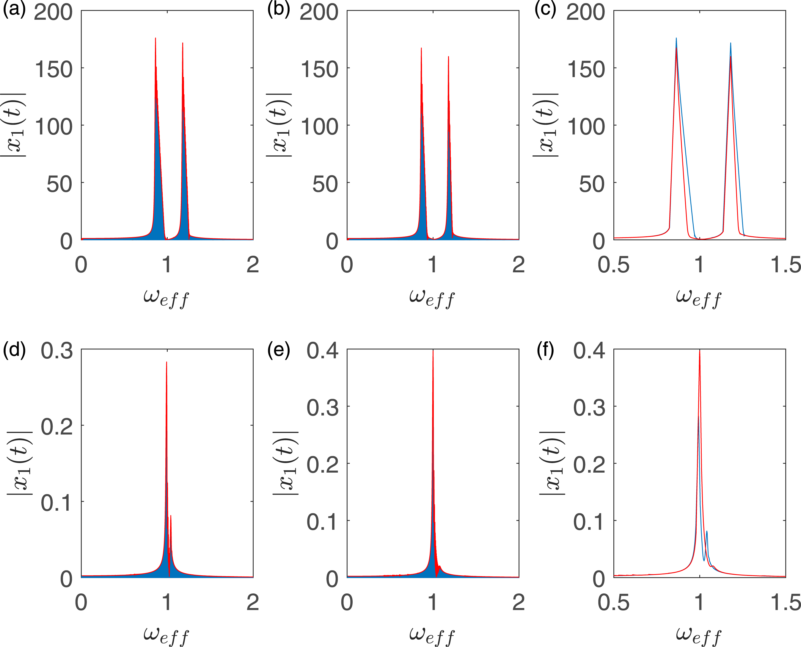
Figures 12(a) and (b) show amplitude versus frequency of the primary mass for TMDs with the Bouc-Wen hysteresis model. Figure 12(c) shows the amplitude versus frequency curves obtained in Figures 12(a) and (b). The blue curve corresponds to the result obtained in Figure 12(a) and the red curve corresponds to the result obtained in Figure 12(b). Note the difference in the resonant amplitudes between the two cases due to the difference in the hysteresis parameters.
Figures 12(d) and (e) show amplitude versus frequency of the primary mass for TMDs with the Bouc-Wen hysteresis model and the hysteresis model of 27 in parallel. Figure 12(f) shows the amplitude versus frequency curves obtained in Figures 12(d) and (e). The blue curve corresponds to the result obtained in Figure 12(d) and the red curve corresponds to the result obtained in Figure 12(e). Note the difference in the resonant amplitudes between the two cases due to the difference in the hysteresis parameters.
From Figure 12, we can compare the results obtained for two different TMD systems. We see that if only Bouc-Wen hysteresis is applied to the TMD system, then the secondary resonance peak is comparable to the primary resonance peak. Also the resonance amplitudes are high. By contrast, if the Bouc-Wen model and the model of 27 are used in parallel, the secondary resonance peak is significantly low as compared to the primary resonance peak. Also, the resonant amplitudes decreases significantly as the damping in the system increases.
Conclusions
In this paper, we have numerically studied tuned mass systems with two different hysteretic dampers. First, we have used the Bouc-Wen hysteresis model as the damper. Next, we have used the Bouc-Wen model and the hysteresis model of 27 in parallel as the dampers. The net damping force is numerically controlled by two parameters α1 and α2. The primary goal of the paper was to numerically study the sine-sweep frequency responses of the TMDs. The sine-sweep response gives a clear description of the amplitude versus frequency. The present study provides qualitative understanding to tune the parameters of the hysteresis models in order to achieve control over the resonant responses.
The study of the TMD with the Bouc-Wen hysteresis and the hysteresis model of 27 in parallel, is novel. We note that the Bouc-Wen model is very famous and extensively used in the field of structural mechanics. We also note that the hysteresis model of 27 is physically motivated. The model was developed from a study of elastic plates with frictional microcracks, with zero residual stress. Due to zero residual stress, the hysteresis loops are pinched at the origin. If we consider a case of engineering material with microcracks with nonzero residual stress, then the two hysteresis models in parallel gives an appropriate model for energy dissipation. In this paper, we have used the physically motivated hybrid hysteresis model in our study and we have found new insights.
The precise role of the individual hysteresis parameter needs to be studied in detail in future. The study will help to quantify the percentage change in the resonant responses of the TMDs if hysteresis parameters are varied. In future work, we will also attempt to develop an analytical or a semi-analytical approach to study TMDs with the hysteresis models discussed in this paper. The study will provide more clearer insights into the interesting nonlinear dynamics of TMDs with hysteresis.
Footnotes
Acknowledgements
We thank two anonymous reviewers whose comments helped us to significantly improve the paper.
Declaration of conflicting interests
The author(s) declared no potential conflicts of interest with respect to the research, authorship, and/or publication of this article.
Funding
The author(s) received no financial support for the research, authorship, and/or publication of this article.

Appendix A
In this section, we present six different cases of sine sweep frequency responses of the TMD with the Bouc-Wen hysteresis and the hysteresis model of 27 in parallel. The parameters used for each case is shown below.