
Abstract
In this study an analytical model for linear coupling between the two perpendicular transverse vibration modes in a tightened bolt is presented. The model shows an excellent fit with the experimental data suggesting that the coupling is dominantly linear. An experiment is performed to support the linearity claim. Two physical scenarios that could justify the theoretical model is given, one scenario involves asymmetric boundary stiffness and the other one measurements imperfection in location. This work is motivated by its application in structural health monitoring techniques, in particular those based on measuring transverse vibrations of bolts and other beam-like components.
Introduction
Coupling between transverse modes in beam-like systems can manifest due to the presence of nonlinear or/and linear coupling terms in the system’s equation of motion. Such modal interaction may be encountered in many engineering applications, therefore investigating this coupling allows one to understand the dynamic of a structure, which can help, for example, in maintaining the healthy functioning of such a structure. Bolts are one of those mechanical systems that are widely used in engineering applications, and their failure in securing a proper tightening of mechanical components can lead to catastrophic outcomes. Thus a regular checking of proper bolt tightness is essential for safe operation. In (Brøns et al., 2021), 1 it was shown that in a tightened bolt, a coupling between the two transverse modes takes place when the bolt is subjected to a hammer impact, in particular when the bolt tension is insufficient.
In- and out-of-plane vibrations in the two perpendicular transverse directions appear in various engineering problems, for example in wind turbine, helicopter blades, airplane wings, and flexible satellites. (Haight and King, 1972) 2 investigated the stability of the in-plane response of a beam that is laterally excited. In their study, they included inertia nonlinearities, and showed that in-plane response can lose stability, resulting in stable out-plane motion. (Pai and Nayfeh, 1990) 3 investigated the nonlinear non-planar oscillation of a laterally excited cantilever beam. While one transverse mode was directly excited, the other one was indirectly excited through the one-to-one internal (auto-parametric) resonance. The interaction between the two modes was caused by nonlinear coupling (inertia and geometric nonlinearity). It was also shown that for certain beam and load parameters, the non-planar responses can be chaotic. (Stoykov and Ribeiro, 2011) 4 studied the interaction of vibration modes with bending, in different planes, and torsion in the free regime. They included the geometrical nonlinearity in their model, which was based on Timoshenko’s theory for bending and Saint-Venant’s for torsion. (Aghababaei et al., 2009a, 2009b)5,6 included also linear coupling in their model, resulting from beam imperfection. They showed that even if the imperfection is small, the resulting dynamic may differ from when the beam is considered straight. However, when the beam is “perfect” (i.e; straight equilibrium axis, symmetric boundary conditions) the coupling is purely nonlinear (Nayfeh and Mook, 1979). 7
In this work we investigate the coupling between the two transverse vibration modes of a tensioned bolt. We show that the coupling can be dominantly linear, and we give two potential scenarios that may be responsible for this linear coupling. In the following section, the experimental data are signal processed and fitted to a mathematical model. Afterwards, an explanation on the physical cause of the coupling between the two modes is given, then followed by conclusions.
Experimental data
Experimental data for hammer impact
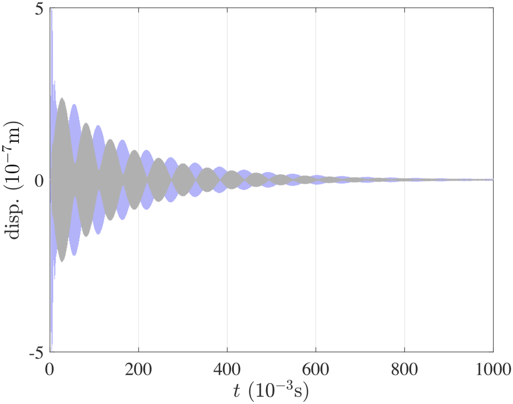
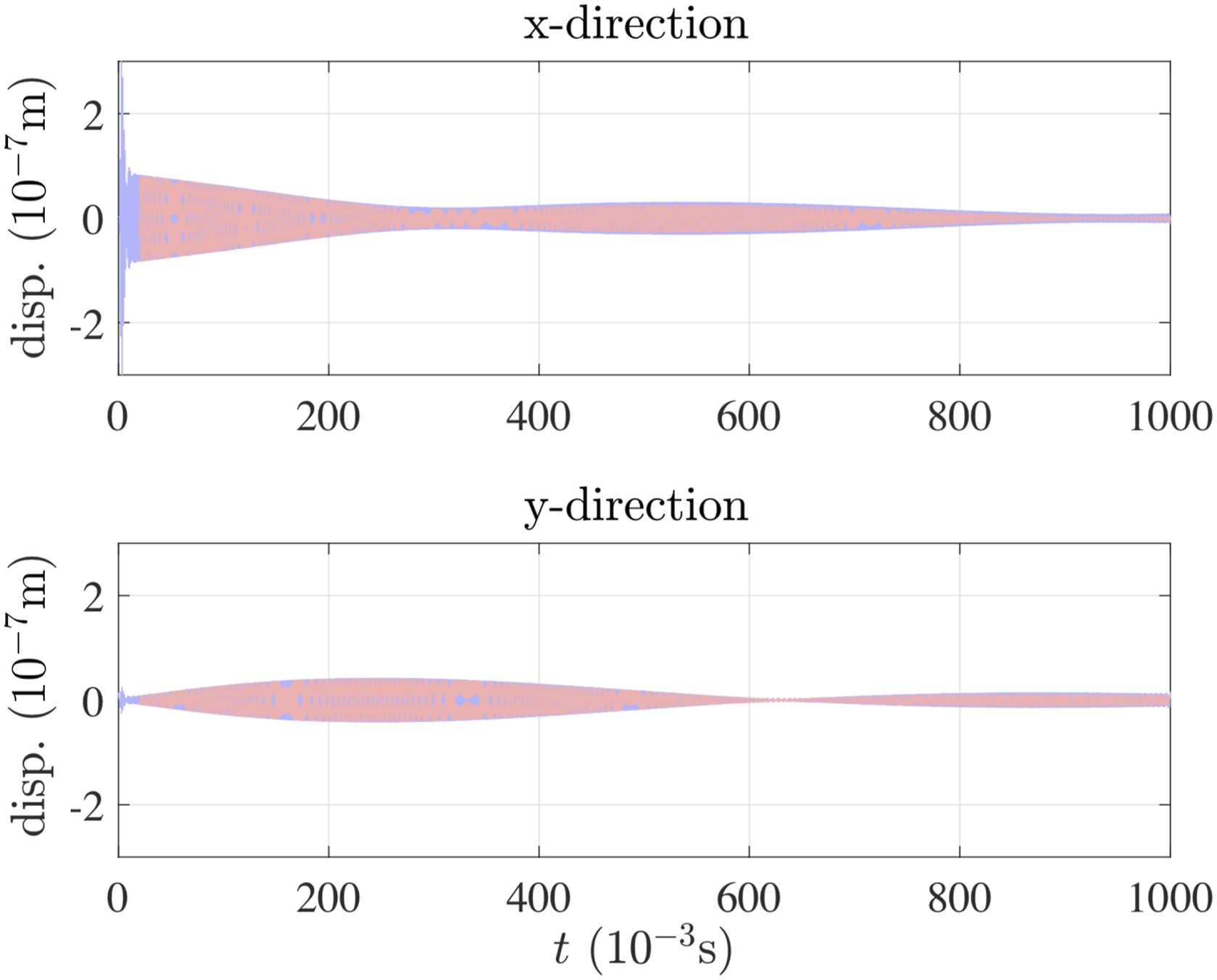
A M12×260 mm steel bolt, mounted in a test rig, is tightened with different tensions and subjected to a hammer impact, Figure 1. The Ø100×200 mm cylindrical test rig is suspended at each end with rubber bands to mimic the free-free boundary condition. The bolt is hammered along a transverse direction “x”, and the responses are sensed using three accelerometers, that are placed along x-, y- and z-directions. Figure 2 shows an example of experimental displacement along the two transverse directions x and y. The figure shows that the amplitude of x-direction is higher than the one of y-direction since the impact is along x-direction. However as the time goes an energy exchange between the two direction modes takes place which results in a beating phenomenon reflecting a coupling between the two modes. Eventually with time, the amplitudes of the two signals decrease and die out due to the presence of damping. In the present work the experimental data given as accelerations in (Brøns et al., 2021),
1
are here displayed as displacements that are obtained by performing Inverse Fourier Transform. A transversally hammer impacted bolt with three accelerometers placed on the nut and the thread end. Experimentally obtained displacement for the two transverse directions. Blue: transverse direction parallel to the hammer impact. Black: transverse direction perpendicular to the hammer impact.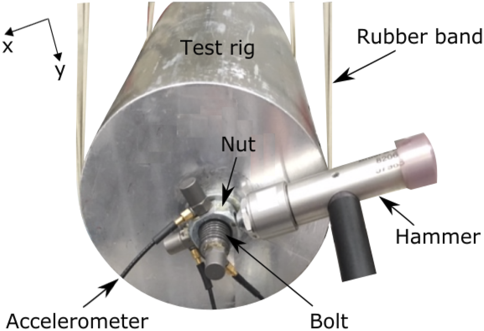
Linearity of experimental data
The equations of motion for the two transverse modes of a beam given in (Nayfeh and Mook, 1979)
7
(ch. 7, equations. (7.1.2)-(7.1.3)) show that for a perfect beam the coupling between the modes is nonlinear. However numerical simulations suggest that mainly the linear coupling is responsible for the beating phenomenon found in our bolt experiment (Brøns et al., 2021).
1
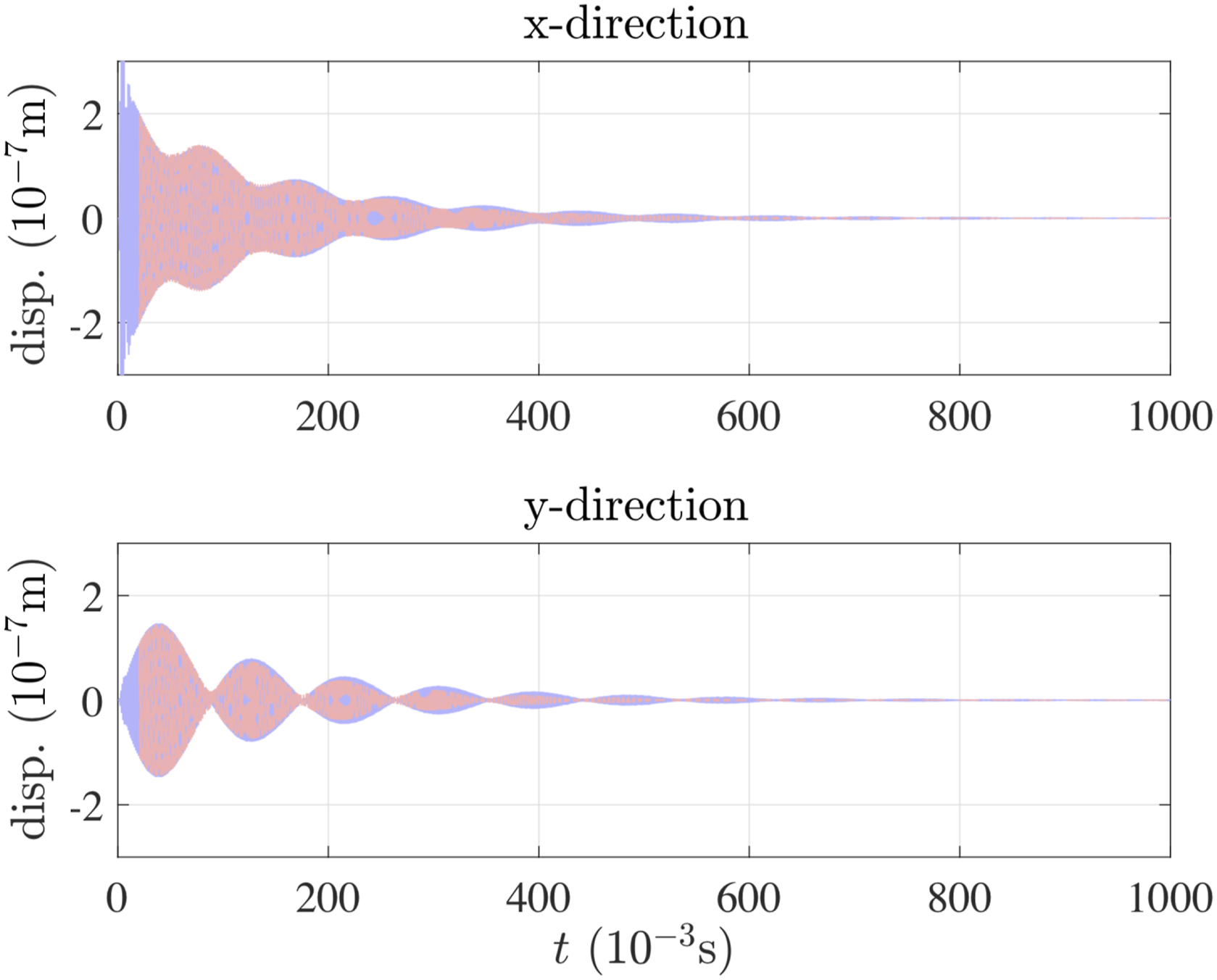
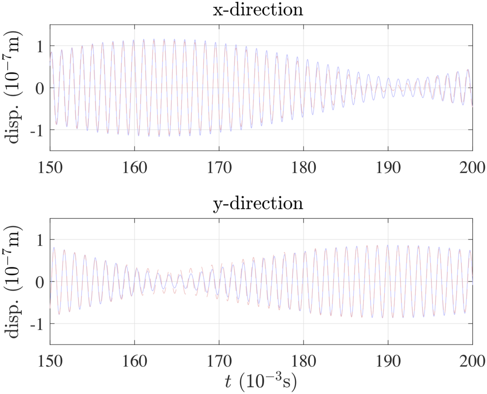
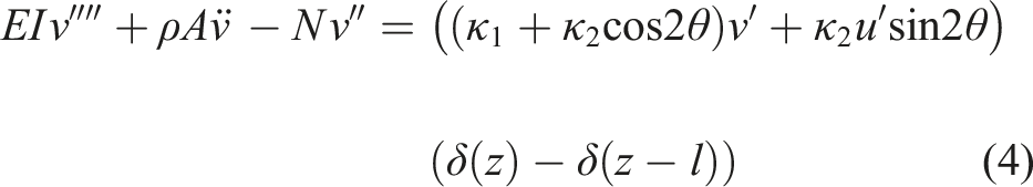
This can be actually noted from Figure 2, where the beating period remains almost constant along the time history, independently of the decaying vibration amplitude. Considering only two modes, a mathematical model involving only linear coupling terms is: Experimental data (blue) and theoretical results (red) for low bolt tension. As the caption in Figure 3, medium bolt tension. As the caption in Figure 3, high bolt tension. Zoom in of Figure 3.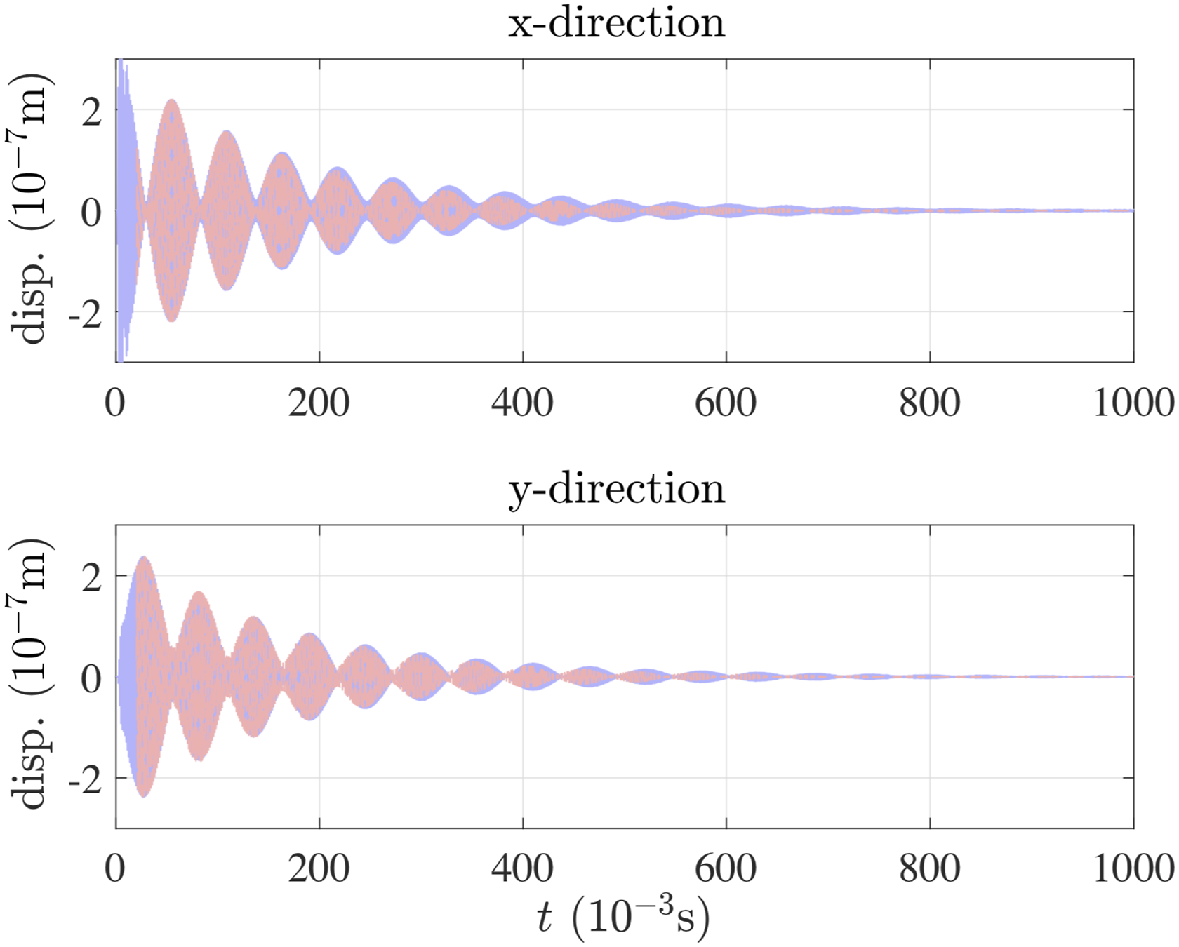


Possible linear coupling mechanism
In this section we investigate two ways that could lead to linear coupling between the two perpendicular transverse modes. Others may exist and all of them act in combination, with different weight in different situations, our main aim is to suggest physically based mechanisms to support the experimentally observed linearity in coupling. The two coupling mechanisms investigated are unrelated to energy dissipation, so to facilitate qualitative insights damping is abstracted from in the modeling.
Boundary imperfection: Skewed boundary stiffness
The first scenario that could potentially produce a linear coupling is due to the boundary stiffness. Given that we are only interested in the first transverse natural frequency, the effect of shear deformations and rotary inertia is small as shown in (Abramovich 1992, Brøns et al.,2019).
8
12
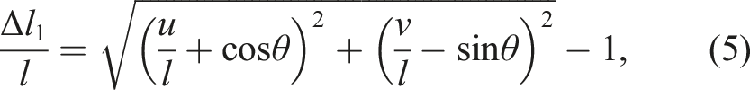
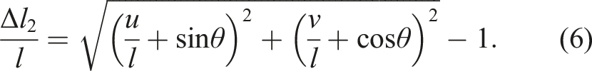
Therefore the bolt is modelled by a Bernoulli-Euler beam where both ends are attached to two “skewed” linear springs, each one forming an angle θ with each of the two perpendicular transverse axes, see Figure 7. That is, the principal axes of the elastic boundary do not align with the principal axes/excited direction for the bolt. Including springs in this manner proved to significantly improve, for example the prediction of natural frequencies of offshore wind turbine (Arany et al., 2015).
9
Applying Bernoulli-Euler theory with the assumption of small slopes, we obtain the equations of motions of the beam in terms of the transverse deflections u (z, t) and v (z, t) (Inman 1996, Thomsen 2021):10,11 Skewed boundary stiffness - two linear springs, each one forming an angle θ with each of the two perpendicular transverse axes (a). Undeformed end springs (b). Deformed end springs (c).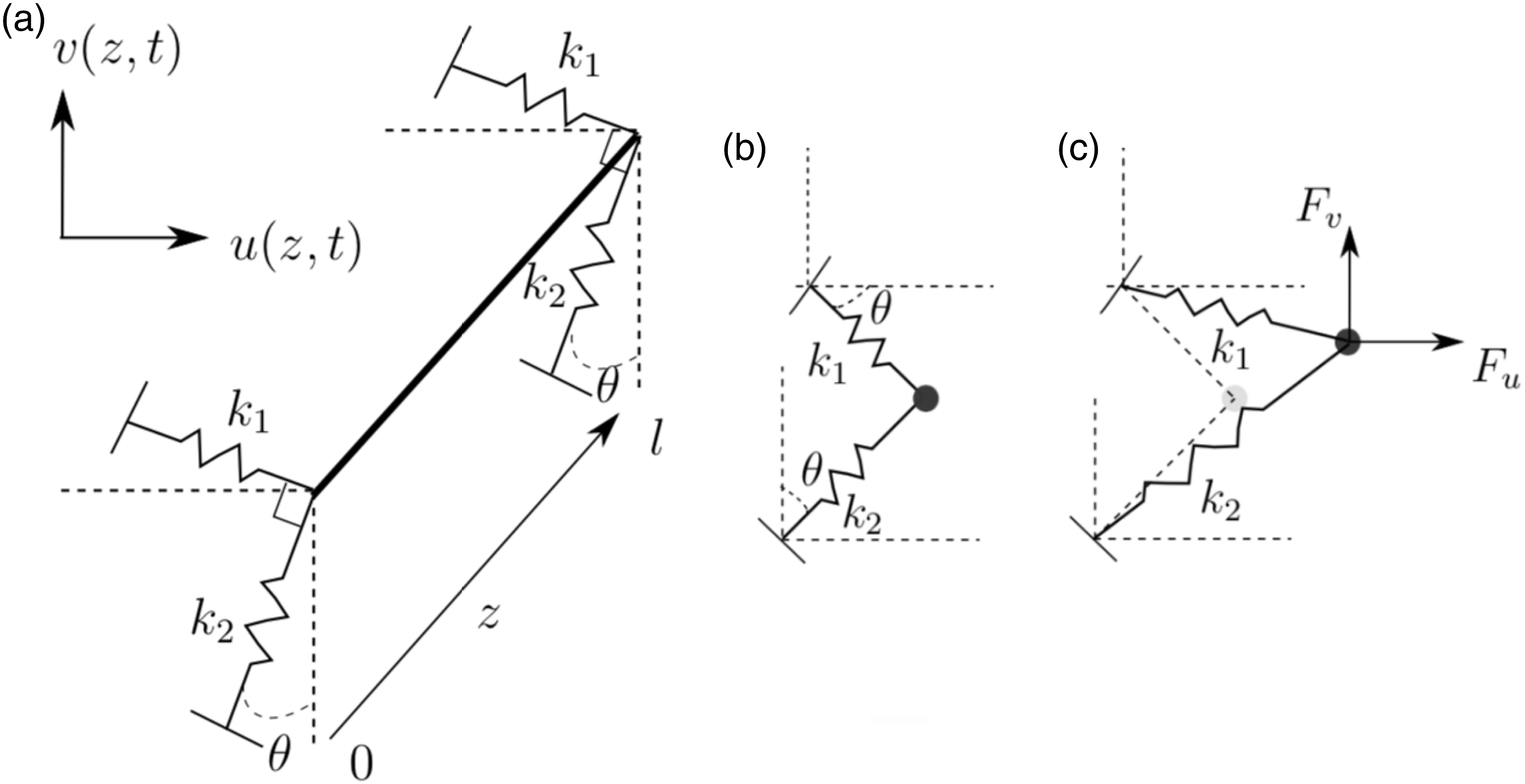
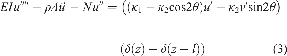
Linearizing the resulting spring forces F
u
= ∂V/∂u and F
v
= ∂V/∂v, in u and v respectively, for small u/l and v/l, and differentiating w.r.t. the variable z gives the r.h.s. of equation (3)–(4), where the 2 θ trigonometric terms reflect the invariance, w.r.t. stiffness, of rotating the spring set 180°. The solutions u (z, t) and v (z, t) to equation (3)–(4), respectively, can be expressed as modal expansions:
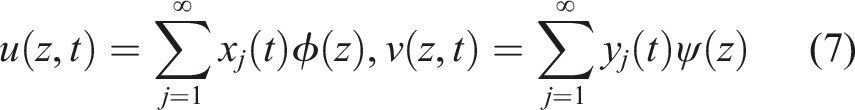
Inserting equation (7) into equation (3)–(4), multiplying respectively by ϕ
i
(z) and ψ
i
(z), and integrating over the length of the beam give:
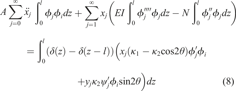
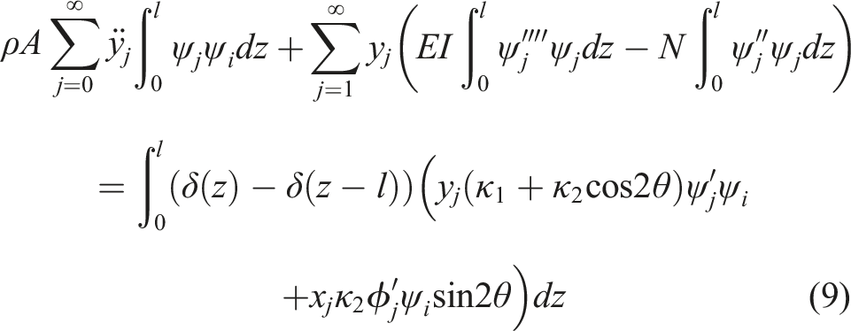
Carrying out the integrals in equations (8)–(9) and only considering the first transverse mode yields:


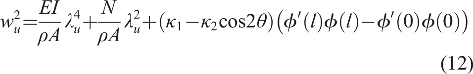
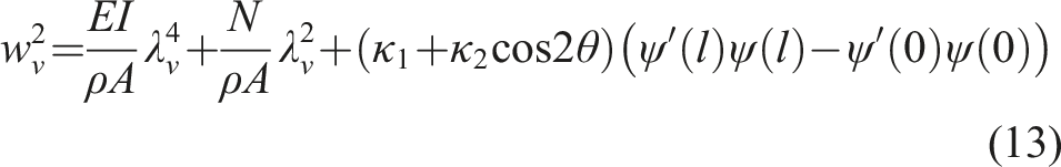
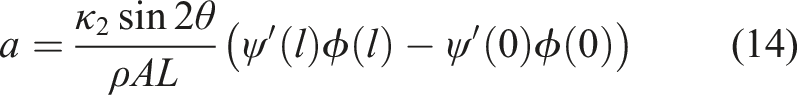
Equations (12)–(15) indicates that coupling (i.e. ab ≠ 0) between the two transverse modes can occur in the case of skewed boundary stiffness if: 1) κ2 ≠ 0, i.e. the two stiffness k1 and k2 are not equal, and 2) the modes shapes and slopes at both ends of the bolt (z = 0 and l) are not equal. It should be noted that similarly rotational boundary stiffness could also be included, however for simplicity only transverse boundary stiffness are included here.
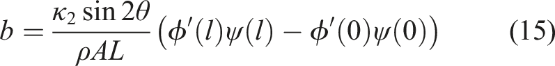
Imperfection measurement directions: Misaligned accelerometers
Another situation where linear coupling between two transverse mode directions x and y can occur - or rather, seem to occur-is when the two accelerometers Schematic of the misaligned accelerometers.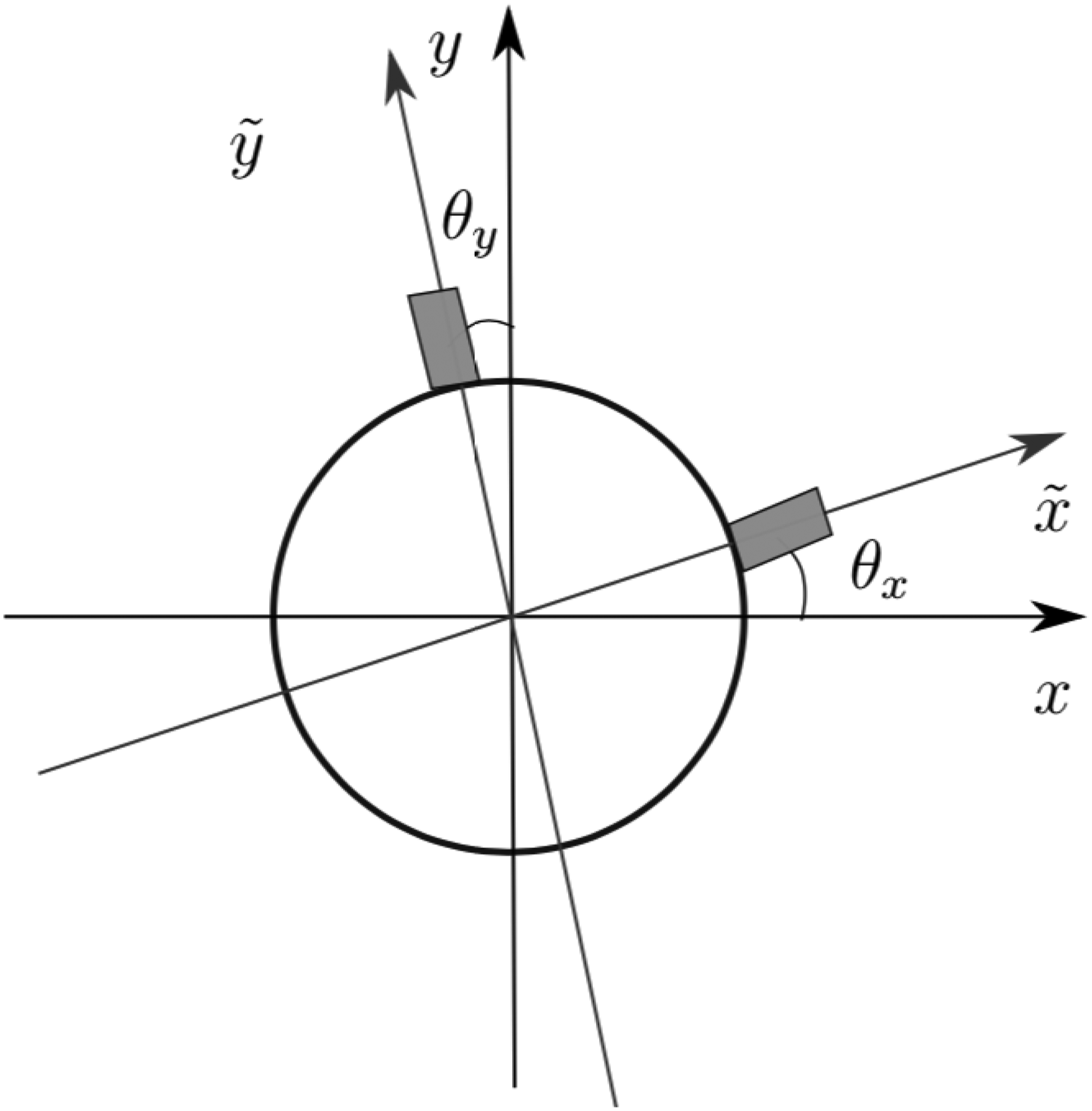
The equation relating the measured accelerations of the two directions
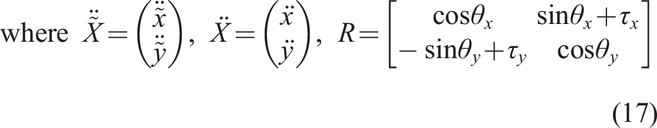
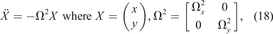
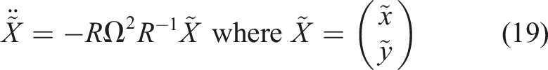

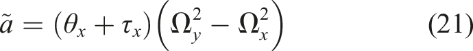
Equations (21)–(22) indicate that misaligned accelerometers can induce apparent coupling between the two mode directions; This occurs when
Conclusion
We showed that several linear mechanisms can explain the observed coupling between two perpendicular transverse modes and derived the conditions when such linear mechanisms disappear. An analytical model with linear coupling terms gave an excellent fit with the experimental data. It was shown that for the first scenario where there is a boundary imperfection, a linear coupling manifests when the two stiffness along each of the two transverse directions, the modes shapes and slopes at both ends of the bolt (z = 0 and l) are not equal. For the second scenario, involving imperfect measurement directions, it was shown that when Ω x = Ω y , i.e. with a perfectly rotational symmetric bolt and transverse symmetric boundary conditions, no linear coupling appears. So, though for a theoretically “perfect” tensioned beam the coupling between transverse vibration modes may be purely nonlinear, for real structures, various sources of imperfection can contribute to linear coupling mechanisms, which dependent on circumstances (type of imperfection, excitation, and measurement set-up) may overrule the nonlinear coupling effects. Imperfection, only two of which are examined in the present work, may be e.g. geometrical (i.e. non-straight undeformed beam axis), structural (e.g. non-uniform boundary stiffness), material (e.g. non-uniform material properties), excitation-related (e.g. non-central hammer impact), or measurement-related (e.g. misaligned sensors).
Footnotes
Declaration of conflicting interests
The author(s) declared no potential conflicts of interest with respect to the research, authorship, and/or publication of this article.
Funding
The author(s) disclosed receipt of the following financial support for the research, authorship, and/or publication of this article: This work is financially supported by Independent Research Fund Denmark (Det Frie Forskningsråd), grant DFF-6111-00385.