



Abstract
Introduction
Reducing vibration of primary system is a topical issue in engineering practice. To overcome this problem, damping devices are commonly used. For this purpose, dynamic vibration absorbers (DVAs) or tuned mass dampers (TMDs) have been developed. In fact, DVA is an auxiliary mass-spring-damper system used to reduce the vibrations of a primary system corresponding to a single-degree-of-freedom system on an elastic suspension, so as to protect it and prolong its service life. The undamped DVA was first introduced by Frahm. 1 However, this original DVA was limited in a narrow damping frequency range around the natural frequency of the primary system. Subsequently, the introduction of damping to the original DVA showed improved control performance characterized by a wider range of damping frequencies and reduced primary system response. 2 Now this damped device is known as Voigt-type DVA, and its optimal design parameters have been found analytically for the first time based on the fixed point theory 2 in the case of undamped primary resonant system. To extend the application of the DVAs to the primary system under random excitation, the H2 optimization technique has been developed. 3 Accordingly, several other designs of DVAs4–6 have recently been studied and tuned according to the H2 optimization7,8 and fixed point theory9,10 in terms of H ∞ optimization. However, as an equivalent device, pendulum dynamic vibration absorber 11 (PDVA) is a special case of DVA, where the moving mass absorber is replaced by a damped pendulum. There are many of its applications in engineering practice. These include, among others, the mitigation of wind-induced vibrations of tall structures such as skyscrapers,12,13 wind turbine towers 14 and tall steel stacks. 15 Furthermore, for vibration reduction of undamped primary structure, the optimal parameters of the classic PDVA have been derived analytically 16,17 under H2 optimization and H ∞ optimization for random and harmonic force excitation respectively. The optimization results for DVAs or PDVA showed that their control performance is related to a large mass of the absorber system which significantly increases the manufacturing cost and make the installation difficult. Besides, the smaller absorber mass may cause that the natural frequencies of the coupled system to be too close which is detrimental to vibration control of primary system. Therefore, with the increasing demand for efficiency and the trend towards lower weight but higher inertia DVAs, it is becoming difficult for these common DVAs to meet the increasing performance demands for vibration suppression in engineering practice.
To overcome the limitations of the common DVAs in vibration reduction of primary structure, researchers have explored other solutions, such as the introduction of negative stiffness devices,18–20 flywheel inertial with lever fixed at ground, 21 and lever mechanism. 22 inspired by. 23 Some research included both negative stiffness and lever mechanism.24,25 They found that the negative stiffness and lever as amplifying mechanism further improve the control performance of DVAs. However, the negative stiffness modeled in these works is linear but difficult to achieve in engineering practice, and the presented DVA with lever mechanism requires too large installation space because the primary system and the absorber system are arranged as two adjacent structures. Therefore, the proposal of a new efficient design model of DVA without negative stiffness may attract special attention. However, from the aforementioned works, it can be concluded that lever mechanism and pendulum are commonly used devices in vibration control engineering. Meanwhile, in the current studies, only one of these two devices is introduced into DVA to improve vibration control. The use of pendulum device as tuned mass damper and lever device as amplifying mechanism have shown better vibration reduction performance in the field of vibration control, respectively. But to the knowledge of the authors, the combined effectiveness of these two devices introduced into the grounded DVA with pendulum connected to the DVA via lever mechanism with ground fulcrum is not known from the literature.
A novel grounded type DVA model is presented in this study by adding a pendulum connected via the lever mechanism with ground fulcrum. The extended fixed point theory is applied to find the optimal parameters of the proposed model. As the equivalent stiffness ratio must be positive, it is found that the amplified mass ratio has a better operating range when the stability condition is met, and the influence of the amplified mass ratio on the vibration amplitude of the primary system is analyzed. The DVA model in this study was proven to have a strong effect on vibration reduction, resulting in a smaller primary system amplitude than the uncontrolled one and a wider absorption frequency band. Modeling of the proposed DVA presents the model in which the analytical solution is found and the study of stability is performed. In Parameters optimization, the parameters are optimized based on the extended fixed point theory and the correctness of the primary system response with the optimal analytical parameters is verified numerically. By comparing the proposed model with other models under harmonic and random excitations in Results analysis, it can be seen that the proposed model has much higher control performance than the considered DVAs counterparts. The conclusion is finally drawn in Performance comparison.
Modeling of the proposed DVA
The grounded DVA model with pendulum connected via the lever mechanism is presented in this study as shown in Figure 1 without generalities. The lever arm (ON) and pendulum rod (OM) are joined at a movable support point O with grounded fulcrum, and a slider is provided at the left end of the lever which is connected to the DVA. The DVA and the pendulum are articulated to form a complete system. m2 and k2 are respectively the mass and stiffness of the DVA with c2 the coefficient of grounded damper. The mass m0 of the pendulum is fixed at M, and ℓ
a
and ℓ
b
are respectively the distance between the fulcrum O of the lever and the attached points M and N. Besides, for the main system, m1 and k1 are considered respectively as the mass and the stiffness. However, the amplitude and the frequency of the excitation force are respectively f0 and ω. Here, the assumption of small displacement amplitudes of the main system is considered, so that the influence of the circular movement of the left end N of the lever can be omitted. As a result, the mass of DVA all moves linearly in the vertical direction. According to the currently mechanical engineering, the physical implementation of the presented lever-pendulum system with grounded fulcrum can be easily realized, so this layout can be used in the many fields of practical engineering. Mechanical model of the proposed dynamic vibration absorber.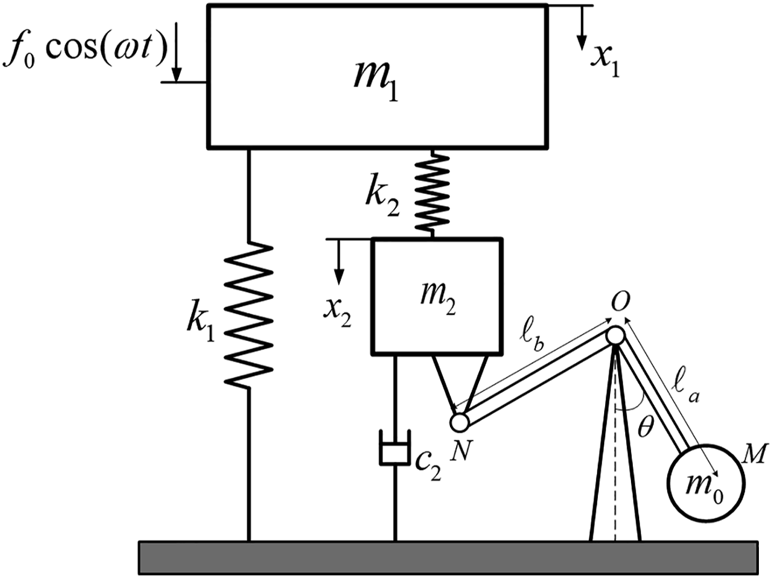
Dynamic equation of motion
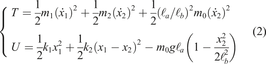
According to Figure 1, x1 and x2 are the primary system and absorber system displacements, respectively. Furthermore, θ is the angular displacement of the pendulum as shown in Figure 1. Therefore, the kinetic energy T and potential energy U of the system shown in Figure 1 are given by





The analytical solution
When the main system is subjected to harmonic excitation let represented as f0e
iωt
, the steady-state displacement solutions of each degree-of-freedom of the coupled system can be represented as


By making the undamped part of the denominator of equation (8) to be zero, the natural frequencies of the coupled system in Figure 1 can be obtained as


Parameters optimization
In this section, the objective is to minimize the maximum vibration amplitude of the primary system around its natural frequency. However, for the system parameters selected as μ = 0.1, δ = 0.6, β = 3 and α = 1.9, Figure 2 shows the plot of the amplitude-frequency curves of the primary system response for different values of the damping ratio randomly selected as 0.1, 0.2 and 0.3. It can be seen that all the curves pass through two points P and Q independent of the damping ratio. Accordingly, the fixed point theory of Den Hartog9,10 is used here in terms of H
∞
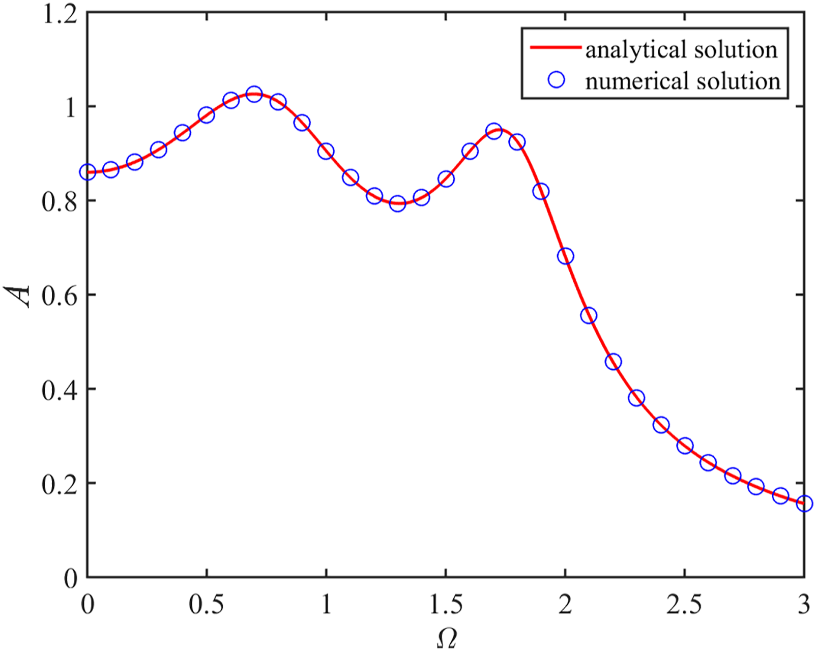
optimization26,27 to derive the optimal parameters of the proposed model. (Figure 2) The normalized amplitude-frequency curves for different damping ratio. The normalized amplitude-frequency curves comparison between analytical and numerical solution.
Closed forms solutions
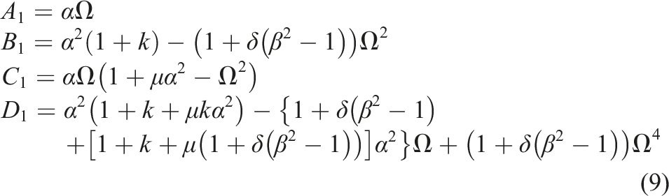
According to the fixed point theory, when the damping ratio approaches zero and infinity respectively, the corresponding amplitude amplification factors can be found respectively. As results, the abscissas of the fixed points P and Q are found when the above corresponding amplitude amplification factors have the same value, that is

Substituting equation (9) into equation (11) leads to

It could be found that there is meaningless situation when the right part in (12) is positive. Accordingly, taking the negative one and simplifying the equation, we can provide

Because equation (13) is a quadric equation in Ω2, it is assumed to have two real roots

Furthermore, when the damping ratio approach infinity, the amplitude amplification factor of the primary system response can be expressed as

First, the objective is to align the two fixed points P and Q at the same height. Thus, according to the fixed-point theory, the two fixed points P and Q have the same height according to equation (15) when


Combining equation (14) with equation (17), one can obtain

Solving equation (18), the optimum tuning frequency ratio is provided as

Then, substituting the optimum tuning frequency ratio into equation (13) and solve, we could obtain the abscissas of the two fixed points P and Q in the frequency axis as


When the optimum frequency ratio and the abscissas of the fixed points are taken into equation (15), the primary system response at the fixed points can be obtained as

When the total mass ratio μ and the mass ratio δ in the DVA system and the magnification ratio β are constant, equation (21) shows that the considered equivalent stiffness ratio k can change the control performance of the DVA system. Moreover, it can been seen that the introduction of pendulum device connected to the lever arm will cause a downwards static pre-displacement of the primary system at zero-excitation frequency where there is a third fixed point R. Therefore, in order to minimize the peak vibration amplitude of the primary system in low frequency region, the optimal value of the considered equivalent stiffness ratio k can be derived by approximating the pre-displacement as the amplitude of the primary system at the fixed points. That is, we can further adjust the three fixed points R, P and Q at the same height, which means that the response of the primary system at zero-excitation frequency (Ω = 0) should be the same as the response at the excitation frequency Ω
P
and Ω
Q

Accordingly

Solving equation (23) with respect to the ratio k, one can get all the possible optimal values as



From the above result, it was found that the above six alternative optimal equivalent stiffness ratio can make the system unstable when the amplified mass ratio in the DVA system is inappropriate. Therefore, in order to guarantee the stability of the coupled system, it is deduced that the amplified mass ratio of the absorber must have a better working range in the optimal design process into the DVA system. However, according to the physical properties of the components, it is known that the lever arm length ℓ
a
, the magnification ratio β the gravity intensity g, the pendulum mass m0 and the stiffness k2 of the system are all positive, which means that the considered equivalent stiffness ratio

Once the optimal tuning frequency ratio and the optimal equivalent stiffness ratio are calculated, the optimum value of the lever arm length ℓb.opt and the pendulum length ℓa.opt are given by

So far, the optimal tuning frequency ratio and the optimal equivalent stiffness ratio are found, which allows only the three fixed points to be adjusted to the same height. However for the optimal control performance, the fixed points should be the highest points of the primary system frequency response curves, with means that the maximum amplitude of the primary system should be located at the fixed points. According to the non-damping conditions at the fixed points P and Q, it could be achieved if the derivatives of the amplitude amplification factor of the primary system with respect to the excitation frequency is zero at the fixed points P and Q

Solving equation (27) and substituting the optimal tuning frequency ratio and the optimal equivalent stiffness ratio into the results, one can obtain


Taking the average of

The working range of amplified mass ratio
When selecting optimal equivalent stiffness ratio k
opt
, it was mentioned that it should satisfy the natural frequencies of the coupled system which are positive given the working range of the amplified mass ratio in the DVA system. However, it is known that the magnification ratio β is greater than unity and all the existing coefficients are positive, which means that in the calculation process of the optimal parameters, the amplified mass ratio in the DVA system should also satisfy the denominator in each expression such that it is not equal to zero, the part under the radical is greater than zero, and the square optimal tuning frequency ratio
Substituting the optimal equivalent stiffness ratio into the optimal tuning frequency ratio, one can obtain

Therefore, the amplified mass ratio δ(β2 − 1) should satisfy

Solving equation (31), one can get

Results analysis
Comparison of numerical and analytical solution
To validate the accuracy of the obtained analytical results from the fixed-point theory (FPT), the numerical simulation is performed here based on the Runge-Kutta method (RKM). To simplify, λ = δ(β2 − 1) is noted as the amplified mass ratio. Therefore, for given total mass ratio as μ = 0.1, the corresponding working range of the amplified mass ratio is (4, 19). Then, amplified mass ratio λ = 5 and excitation amplitude f0 = 1000N are selected. According to the analytical results, the optimal parameters based on the FPT are α = 3.4800, ξ = 1.2819 and k = 0.0954. The initial conditions are chosen such as
The influence of amplified mass ratio on the primary system response
The influence in the working range
The optimal parameters in different case of amplified mass ratio.

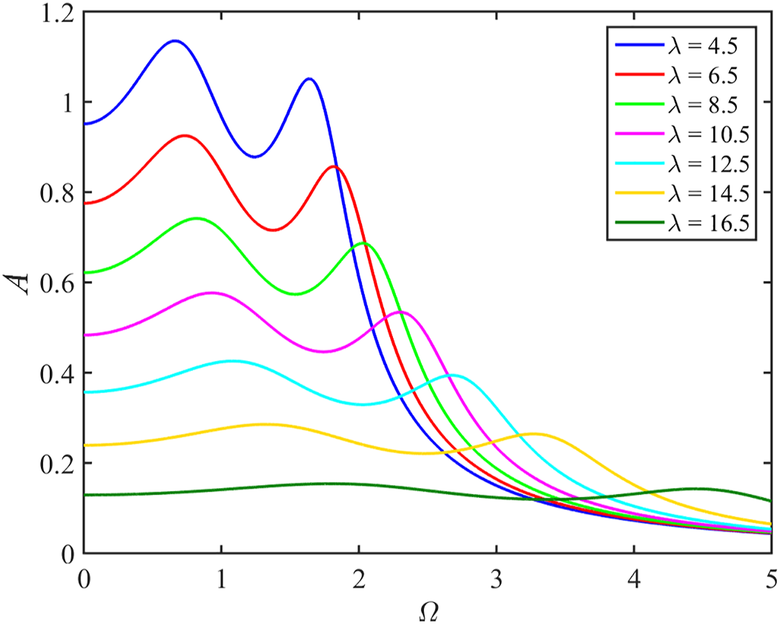
The effect of the amplified mass ratio on the primary system response.
The influence outside the working range
When installing the optimally designed DVA, the installation space can be reduced, requiring a small amplification ratio. However, such a situation can be taken into account by the proposed DVA design without degrading its control performance. For example, when the total mass ratio is selected as μ = 0.1, the working range can be calculated, and the value of the amplified mass ratio slightly higher than the lower limit of the working range λ = 4.1 is chosen, which correspond to the optimal parameters k = 0.0099, α = 3.1939 and ξ = 1.1348. Based on these optimal parameters, the frequency response curves of the primary system are plotted for the values of the amplified mass ratio less than the lower limit of the working range, i.e. λ = 0.5, 1.5, 3 and 4, respectively. The result of the plotted runs is shown in Figure 5. From Figure 5, it can be seen that the DVA designed for tighter installation space still has a great damping effect. The response of the primary systems when the amplified mass ratio is less than the lower limit of the working range.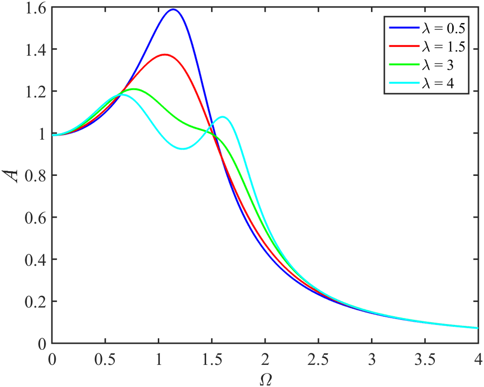
When the amplified mass ratio is larger than the upper limit of the working range, the total mass ratio μ = 0.1 is chosen, and the value of the amplified mass ratio slightly lower than the upper limit of the working range λ = 18.99 is selected. The optimal parameters at this time are k = 0.9995, α = 199.9625 and ξ = 3.1611. However, the optimal tuning frequency ratio is quite huge, which is difficult to achieve in practice. Therefore, it is necessary to avoid the situation where the amplified mass ratio is very large.
Performance comparison
In order to better quantify the damping vibration effect of the proposed DVA model in this paper, three other DVA models are considered to be compared. That is, the DVA by Den Hartog,
9
the DVA by Ren
6
and the DVA with negative grounded stiffness by Shen
18
These three DVA models are illustrated in Figure 6. In the following simulation processes, unless otherwise indicated, the mass ratio or the total mass ratio μ = 0.1 is chosen for all DVAs, and the magnification ratio β = 8.5 is selected as an example for the proposed model. According to the optimal design formulas in the literature6,9,18 based on the fixed points theory, the values of the optimal parameters are relevant for each DVA model in Figure 6 which can be calculated. Furthermore, relevant parameters for the proposed DVA model are obtained from Table 1. Two control performance criteria are evaluated here, i.e., harmonic vibration reduction and random vibration reduction of the primary system, respectively, relevant to the frequency and time domains.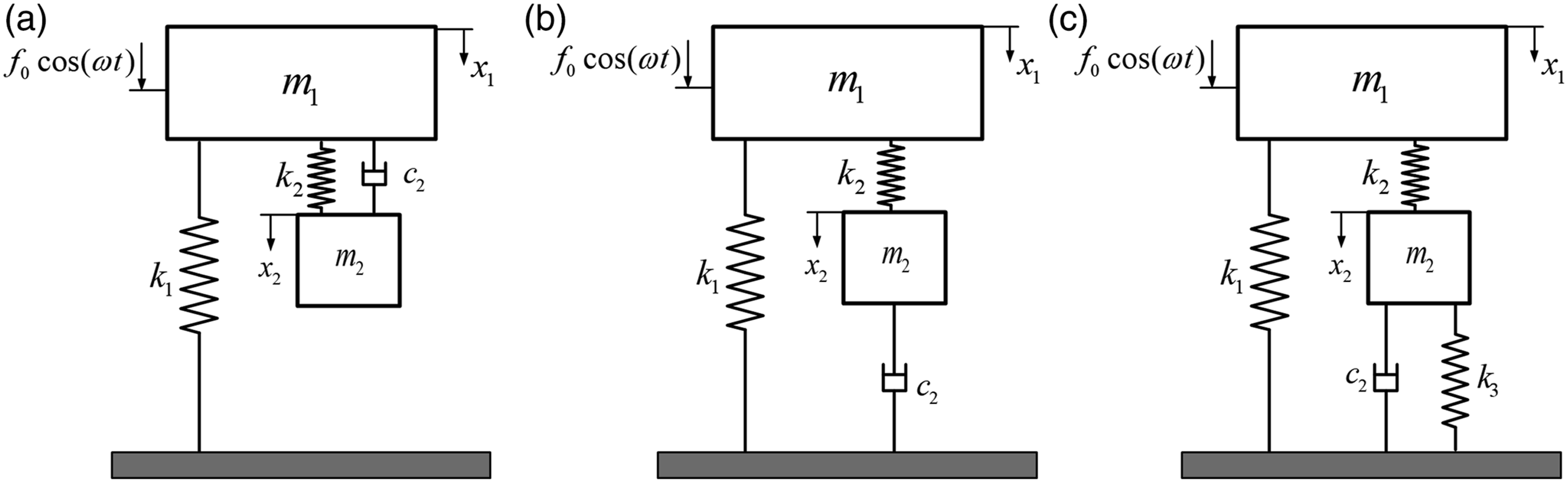
Comparison for harmonic vibration reduction
When the harmonic force excitation is enforced, the objective is to minimize the resonant vibration amplitude of the primary system around the natural frequency. For this purpose, the respective optimum normalized displacement amplitude frequency-curves of primary system pertaining to each DVA is shown in Figure 7. It can be seen from this figure that under the same mass ratio, the proposed DVA model in this article obviously has a greater vibration absorption effect than its DVA counterparts. In other words, the resonant amplitude value of the primary system is greatly lower beyond the uncontrolled static response, and the distance between the two resonant peaks is much wider, so that it has a better control performance in vibration absorption of the primary system. Comparison of control performance with other DVA models.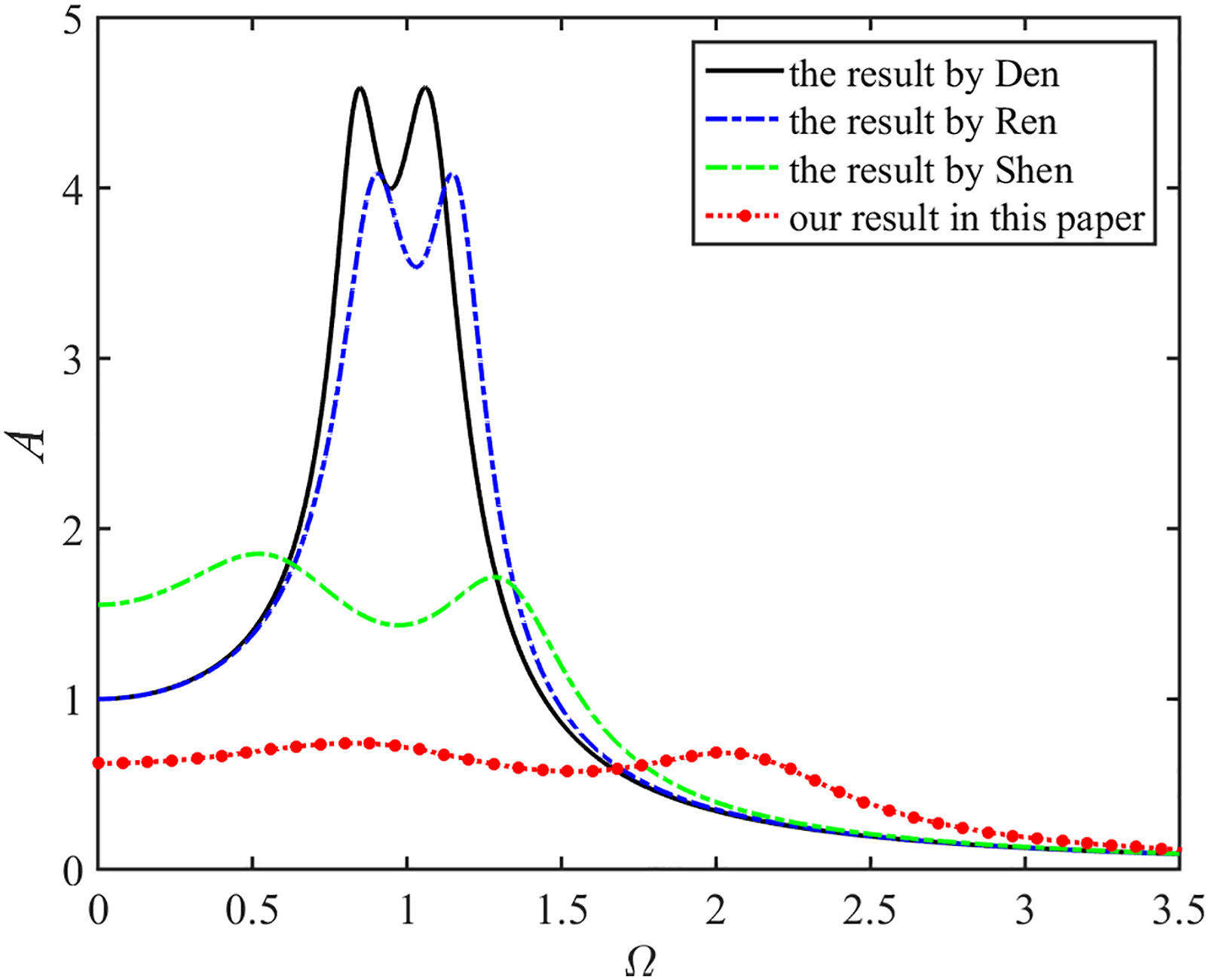
Comparison for random vibration reduction
In many engineering practices, the primary system is under random vibration, which is detrimental to its safety. Therefore, it is necessary and justified to investigate the primary system response under random excitation. Thus, in the case of random excitation of the primary system, the control performance measure is the evaluation of the mean square displacement of the primary system. Consider that the primary system is under random white noise excitation with zero mean and constant power spectral with respect to the excitation frequency as S(ω) = S0. Therefore, the power spectral density functions of the absolute displacement responses of the primary system with Den’s DVA, Ren’s DVA, Shen’s DVA, and the proposed DVA in this paper are respectively, as
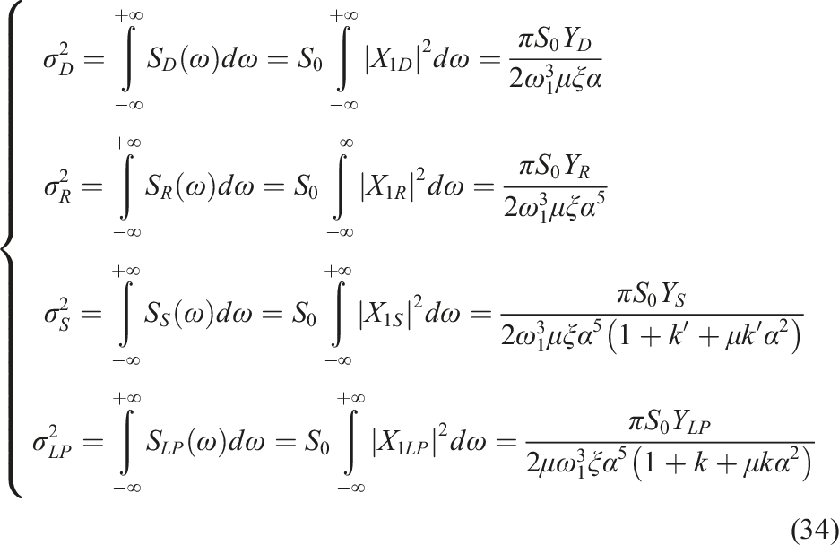

The relevant optimal parameters are calculated for the same aforementioned mass ratio, and the values of the respective mean square displacement of the primary system can be obtained as
The above results show that the proposed DVA model in this paper has smaller response value, so has better random vibration reduction performance of the primary system even under random force excitation, when the mass ratio is the same.
The variance and decrease ratios of the primary system.
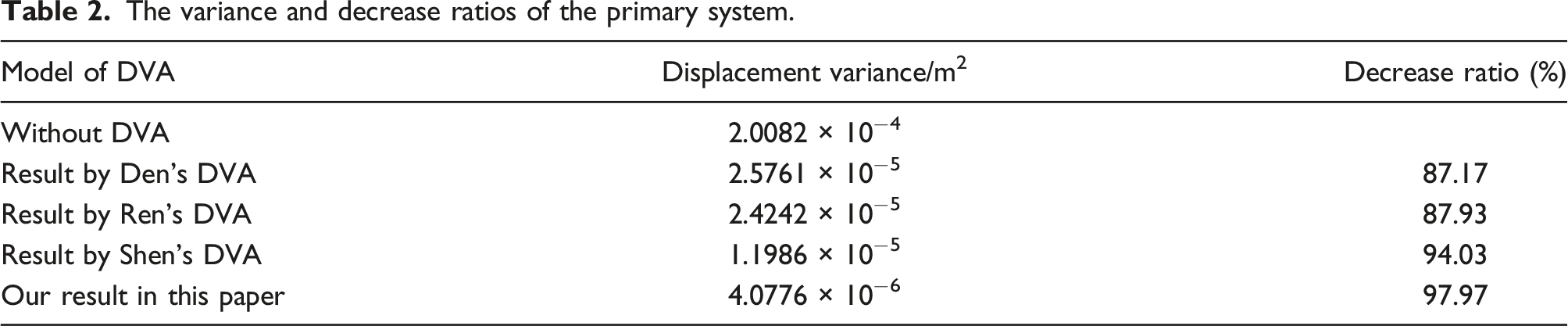
It can be seen from Table 2 that although the presented DVA model in this paper was designed to reduce the harmonic vibrations of the primary system, it can also better reduce the total vibration energy of the primary system in the whole frequency range event random excitation. This result indicates that the proposed model in this paper has far better primary system vibration reduction performance than its DVA counterparts considered for comparison in this study.
Conclusion
The control performance of a novel type of DVA with pendulum connected to DVA via the lever mechanism is investigated in this paper. The optimized parameters of this model are found based on the fixed points theory, as a function of total mass ratio and amplified mass ratio in the DVA. That is, the optimal tuning frequency ratio, the optimal damping ratio and the optimal equivalent stiffness ratio. The results show that to get the non-imaginary and non-negative values of the optimal parameters of the system, the amplified mass ratio should have the working range, which was found. The vibration amplitude of the primary system decreases as the amplified mass ratio increases in the working range. However, it is shown that the presented DVA can be designed for the values of the amplified mass ratio smaller than the lower limit values of the working range, which still has a better vibration reduction effect. Comparing the control performance with other similar dynamic vibration absorbers (DVAs), the results show that under harmonic and random excitation of the primary system, the presented DVA can greatly reduce the response amplitude and widen the effective bandwidth of vibration suppression. This result provide a novel design of dynamic vibration absorber.
Footnotes
The authors would like to thanks the associate editor and the anonymous referees for their valuable comments and suggestions, which helped us to improve the manuscript.
Declaration of conflicting interest
The author(s) declared no potential conflicts of interest with respect to the research, authorship, and/or publication of this article.
Funding
The author(s) received no financial support for the research, authorship, and/or publication of this article.
