
Abstract
The analysis of stiffened plate has been carried out using finite element method. The study is divided into static and dynamic analyses. Primarily, free vibration frequencies of the stiffened plate have been determined followed by determination of deflection and von Mises stress for the stiffened plate subjected to the unit uniformly distributed load (1 kN/m2). Further, deflection and von Mises stress are determined, when the plate structure is subjected to hydrostatic loading. The analyses, static and dynamic, have been done using ANSYS Workbench 15.0. A single flat stiffener is used to stiffen the plate structure and the results are evaluated by varying the stiffener geometry, keeping the volume of material almost same as the unstiffened plate. Stiffened plate structure is very popular in the structural engineering domain and has a wide range of engineering applications from ship to aerospace structures. The material used to model stiffener is extracted from the primary plate for keeping the same volume of material. The plate structure is stiffened to reduce the out-of-plane bending even if the same (approximately) amount of material is utilised. Eight-noded plate bending and two-noded beam elements are used to model the plate and stiffener, respectively. The obtained results are compared with the published results and the effect of varying stiffener geometry is further examined. It may be concluded that the response of the stiffened plates are better compared to unstiffened plate even if the same or even less quantity of material is utilised in stiffening. The present findings are useful for the designers when the plate structure is influenced by the surrounding fluid.
Keywords
Introduction
Plate is a two dimensional flat structural element with thickness, very small compared to other dimensions. It is very popular especially in aircraft and ship construction industries. A plate is broadly characterised as thin or thick based on the thickness of the plate. The formulation of these plates are governed by the plate theories, Kirchhoff–Love theory (classical plate theory) for thin plates, Uflyand-Mindlin theory for thick plates (first-order shear plate theory), followed by higher-order plate theory for laminated composites. The Kirchhoff-Love plate theory is used for the thin plates, where shear deformations are neglected. The Mindlin theory is used for the analysis of thick plates, which accounts for shear deformations. The thin plate theory is used when the shear deformations are comparatively smaller and it is also easy to apply. With the enhancement of load over the structures, there is a need to strengthen the structures. So, to strengthen the plate, the thickness has to be increased, but this will be uneconomical. The economy of the plate structure can be reached by adding a secondary member, called stiffener, and the finally called a stiffened plate structure. Stiffened plates are economical and enhanced the static as well as dynamic response of the unstiffened plate. Numerous studies have been performed to determine the response of plate structure to various loadings. Some of the important literature have been presented in the next paragraph.
The natural frequencies of stiffened plates are evaluated.1–3 A method is presented for static and dynamic analyses of eccentrically stiffened annular sector plates, clamped on all edges. 4 The stiffened plate subjected to air blast loading is investigated. 5 A new approach is introduced for analysing unstiffened and stiffened plates with arbitrary shapes.6,7 A method is proposed to determine the free vibration frequencies of annular 8 and circular plates. 9 A truncated far boundary is developed for compressible fluid 10 and incompressible fluid. 11 The plates (vertical and horizontal) are studied which are affected by surrounding fluid.12–14 Vibration analysis of stiffened plate structure is performed using spline finite strip method. 15 The various stiffener geometries and loadings on the stiffened plate is investigated. 16 A rectangular lock gate interacted with fluid is analysed.17–20 The optimum position to provide the stiffener in the stiffened plate is suggested. 21 Clamped stiffened plate subjected to pressure is analysed to determine the optimum height of the stiffener. 22 Stiffened plate is analysed to find the optimum size of stiffener keeping the constant volume of material. 23 The vibration analysis of lock gate structures, stiffened and unstiffened, is performed.24–27 Free vibration analysis of stiffened plates is carried out using finite element method (FEM). 28 The dynamic response of stiffened plated structures is analysed under moving loads with different velocities using the finite element method. 29 The vibration characteristics of curved stiffened plates is investigated using the finite element method. 30 The dynamic response of stiffened bridge decks is investigated under moving loads for various velocities. 31
The above literature presents the importance to carry out dynamic analysis of plate structures. It has been also concluded that the stiffening of such structures made them stronger against the bending. Thus, the present study focuses on the analysis of stiffened plate structure subjected to static and dynamic loadings. The theoretical formulation of stiffened plate structure are very well known in literature 24 and are not presented separately for the conciseness of the paper. Only finite element modelling is presented in the next section for the ease of the reader.
Finite element modelling
A square plate having width B 1000 mm with 10 mm thickness is considered in the study using ANSYS Workbench 15.0. The thickness of the lock gates (unstiffened or stiffened) are chosen based on the minimum thickness criteria specified in IS: 800-1984 (Clause no. 3.8.2),
32
i.e., 6 mm. A stiffened plate with single stiffener (eccentric), as shown in Figure 1, is used in the present study by varying the stiffener’s geometry as per IS: 800-2007 (Clause no. 8.7.1.2),
33
keeping the volume of material almost constant as that of unstiffened plate. The outstand (o
s
) of the stiffener should be between 14t
s
ε and 20 t
s
ε, where Geometry of stiffened plate.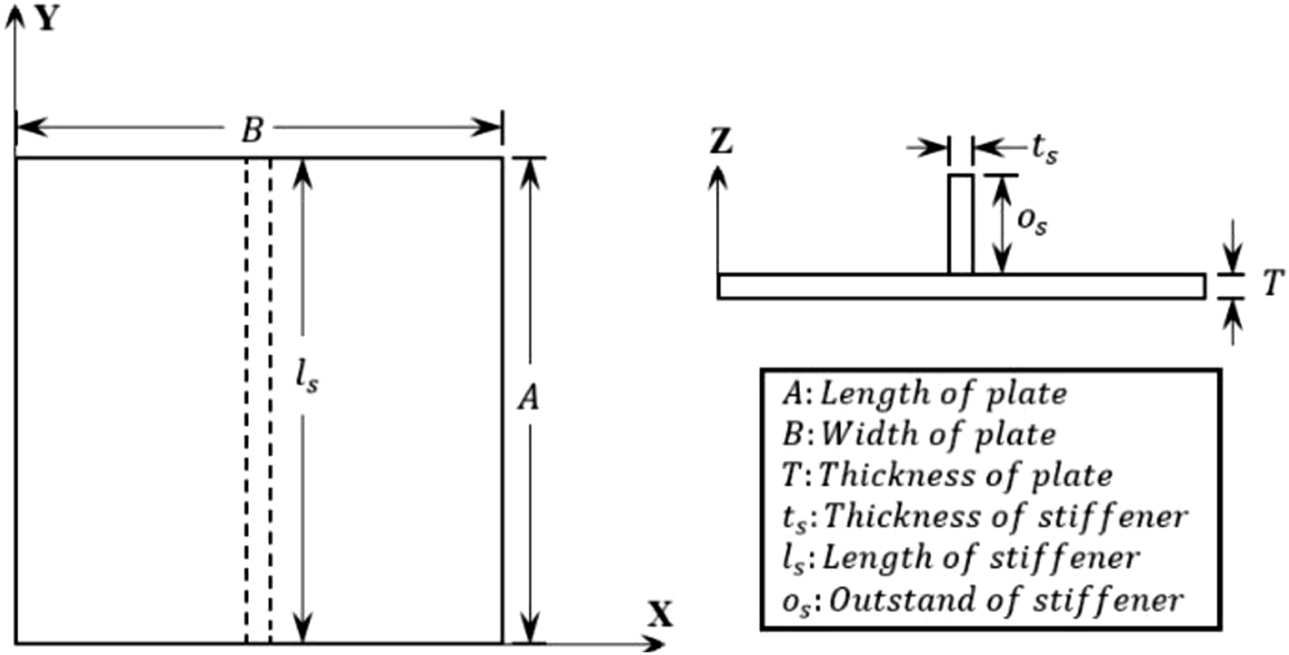
The study is divided into two parts, analysis of unstiffened and stiffened plates, which is further characterised as static analysis and dynamic analysis. Maximum deflection, maximum von Mises stress, and fundamental frequency are evaluated in the analysis. All edges clamped and simply supported boundary conditions are considered in the study. SHELL281 (eight noded element having six degrees of freedom at each node) and BEAM3 (two noded element having six degrees of freedom at each node) elements are used for modelling of square plate and stiffener, respectively, in ANSYS. But, before proceeding to the analysis, convergence study has been carried out to find the optimum mesh size. The six degrees of freedom in context to stiffened plate structure is shown in Figure 2. Degrees of freedom (single arrow: translation, double arrow: rotation).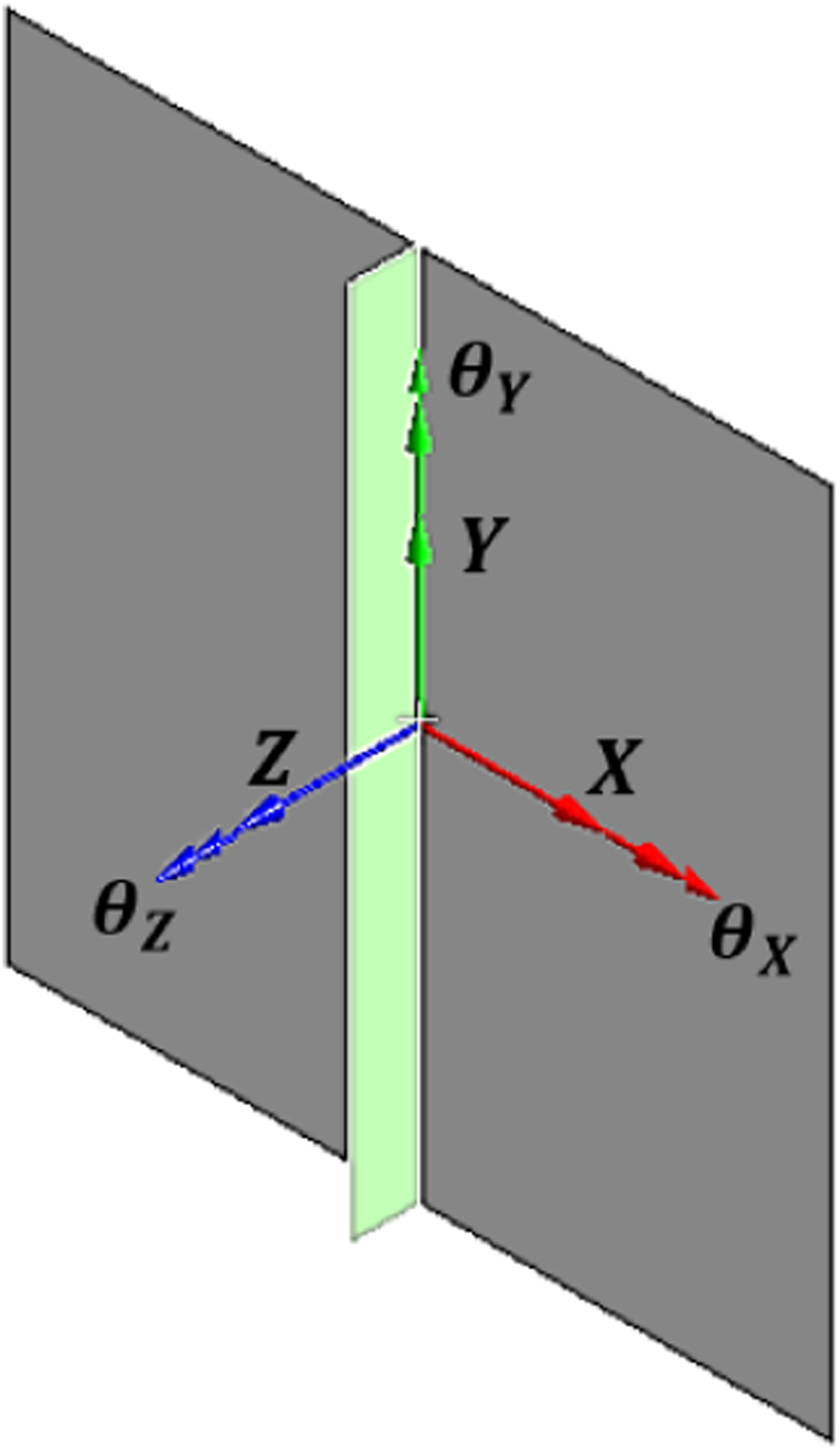
Convergence study
A convergence study is performed on the unstiffened plate to determine the optimum mesh size for the analysis as shown in Figure 3. The static analysis is carried out on unstiffened steel plate with uniformly distributed load of 1.0 kN/m2. For the dynamic analysis, fundamental frequency has been determined. The result of maximum stress is not put into the figure of convergence study simply for the sake of brevity. It is found that results are converging after the mesh division of Convergence study. (a) Maximum deflection (b) Fundamental frequency.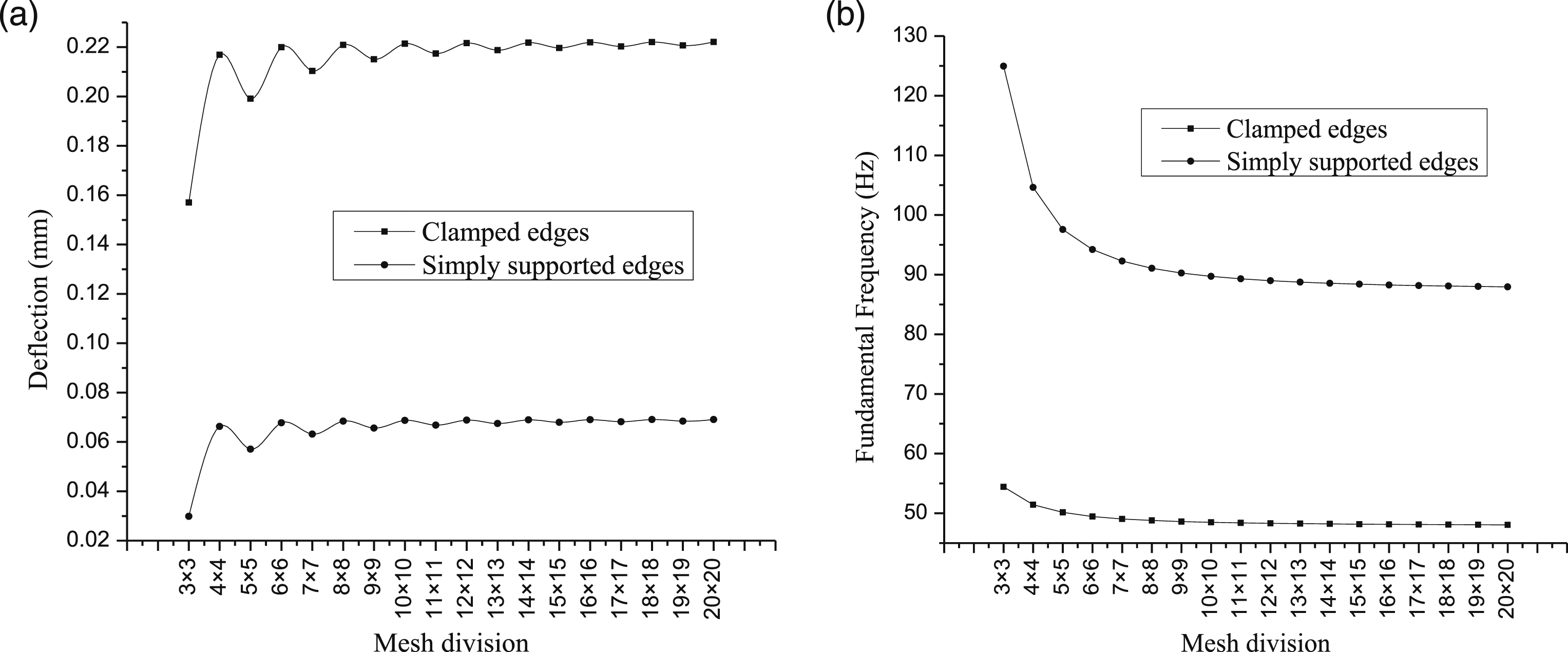
Numerical results and discussions
As stated above, the analysis is divided into two parts, analysis of unstiffened and stiffened plates for estimating the static and dynamic responses. For the static analysis, maximum deflection and maximum von Mises stress are determined subjected to uniformly distributed load of 1 kN/m2 and hydrostatic load, and fundamental frequency is evaluated for the dynamic analysis. The hydrostatic load is shown in Figure 4 for better understanding of the readers. Hydrostatic load.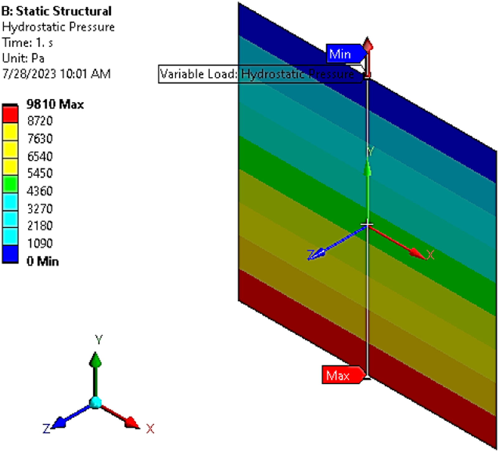
Several numerical examples are presented in the next section based on the above mentioned analyses. The two boundary conditions, clamped on all edges and simply supported on all edges, are considered in the analyses.
Validation
Before proceeding to the numerical investigation, the present approach, i.e., analysis using ANSYS software, it has to be validated with the published results. The results obtained using the present approach is validated with stiffened plate (clamped) results reported by Olson and Hazell
1
(experimental) and Nayak et al.
3
(FEM Code). The comparison are plotted in Figure 5, which reveals a good agreement. Validation of results.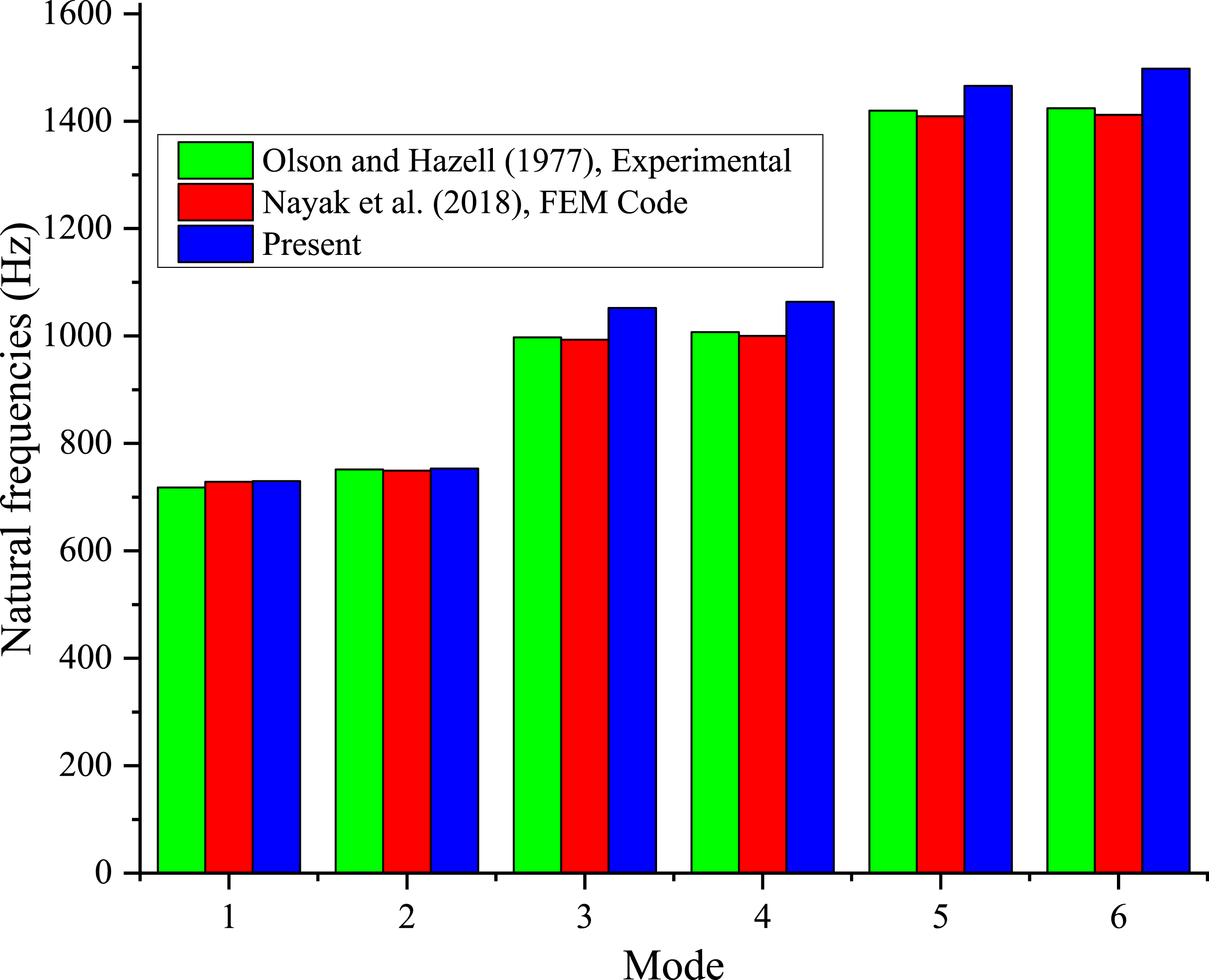
Static analysis
Uniformly distributed load
The square unstiffened plate with width B 1000 mm and 10 mm thickness is considered subjected to uniformly distributed load of 1.0 kN/m2. The contours of deflection and stress are shown in Figure 6 for both the boundary conditions. It is observed that the maximum values of deflection and stress are more for clamped edges compared to simply supported boundary conditions. The maximum value of deflection and stress are 0.0687 mm and 1.818 MPa, and 0.2214 mm and 3.2019 MPa for clamped edges and simply supported edges, respectively. Maximum value of deflection and von Mises stress.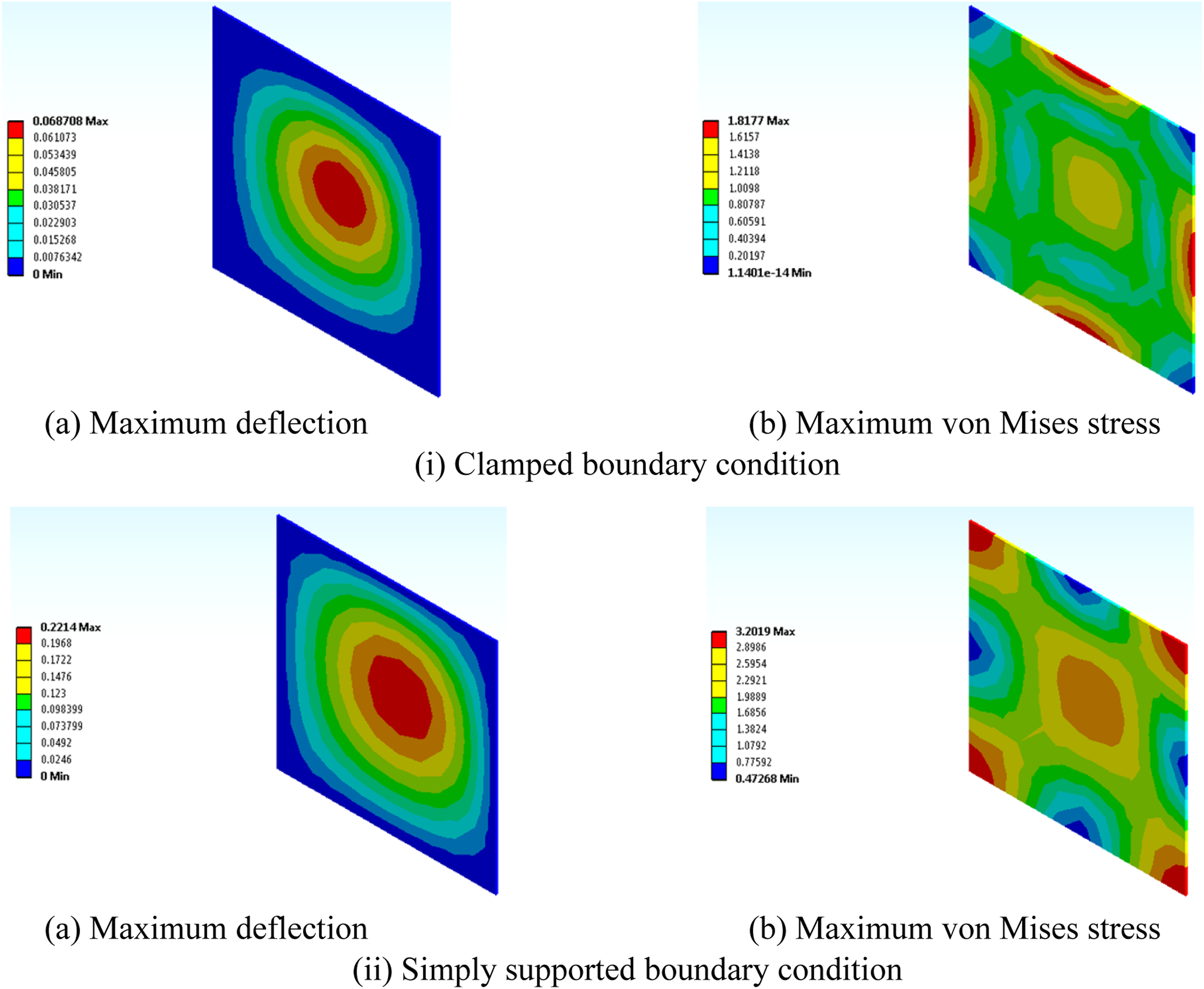
The value of deflection is maximum at the centre as the applied load is symmetrical over the plate. For the clamped edges, all degrees of freedom, i.e., all the six are restricted at the edges. For the simply supported edges, five out of six degrees of freedom are restricted at the edges, only one rotation (around X-axis or Y-axis on alternative edges) is allowed on the respective edges. Hence, the value of deflection is zero at the edges in both the boundary conditions, also beyond the edges up to certain distance the value is zero, the distance is more in case of clamped edges due to restrictions on degrees of freedom.
The value of stress is more where more restrictions are there, like at the edges in the clamped edges and at the corners in the simply supported edges. Also, at the centre, stress is prominent as the plate is deformed maximum there, but quite less than the maximum value. If the value of load is increased, the stress at the edges/corners and at the centre will become same. On the contrary, the value of stress is minimum at the corners in clamped edges condition and at the edges in simply supported edges condition. In order to control the material usage and expect enhanced response, the plates have been stiffened and the variation is analysed and reported.
Now, the plate is stiffened using a single stiffener by extracting the material from the plate to maintain the constant (almost) volume of material as that of unstiffened plate. The dimensions of the stiffener are based on the specifications of IS: 800-1984
32
and IS: 800-2007.
33
The minimum thickness of the stiffener is kept as 6 mm and outstand as 14t
s
ε and 20t
s
ε. The contours of deflection and stress are shown in Figure 7, having 84 mm outstand. Maximum value of deflection and von Mises stress.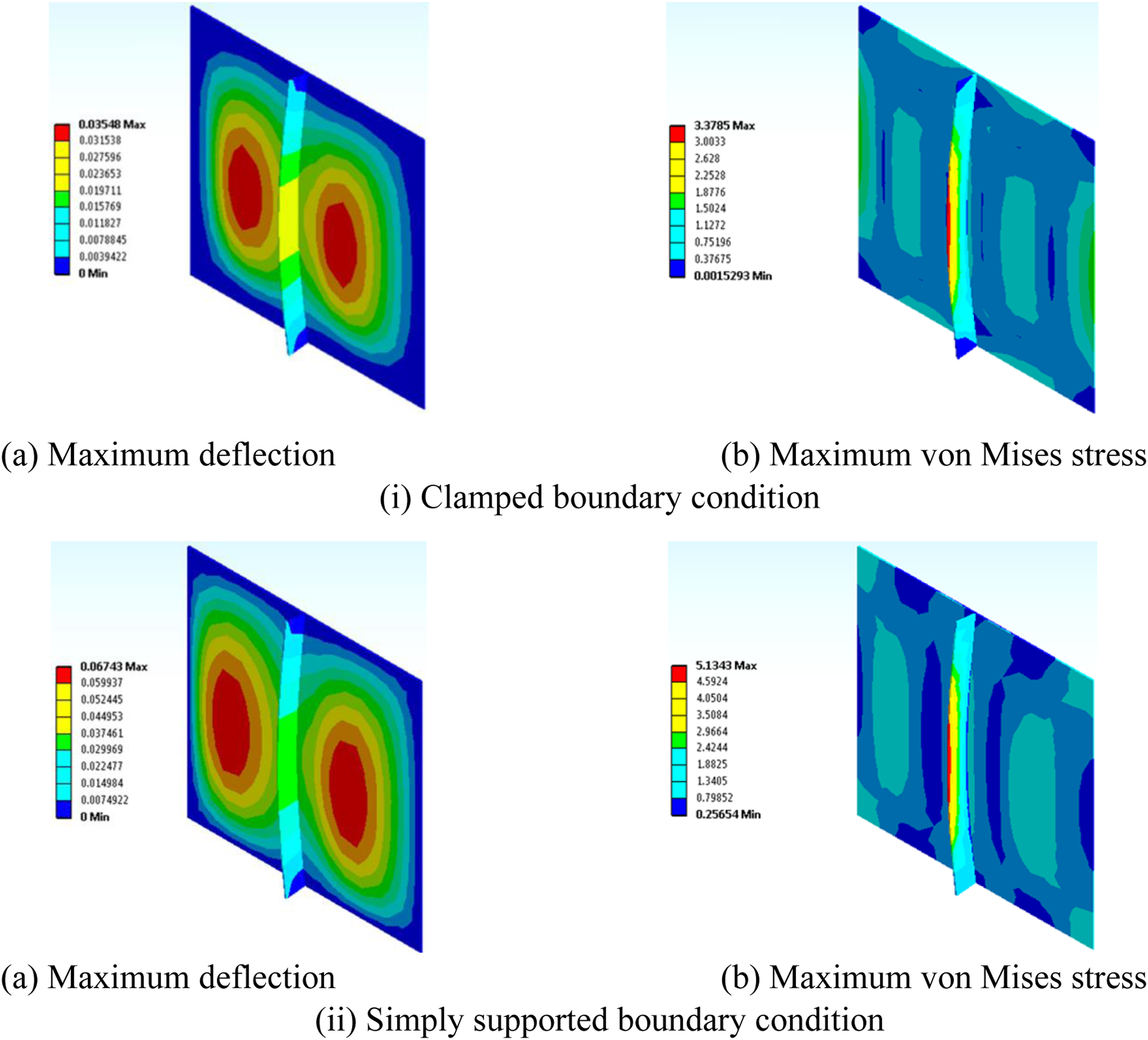
Further, considering the minimum thickness criteria specified in IS: 800-1984,
32
plates are modelled and the responses are recorded, as shown in Figure 8(i), subjected to uniformly distributed load (UDL). It is clearly seen that with the increment in thickness of the plate, the deflection and stress are decreased. It means that the response of the plates are enhanced when the thickness is increased, but at the same time the consumption of material is also increased. The results of deflection and stress with varying the thickness of the plate keeping the thickness of stiffener as 6 mm are shown in Figure 8(ii), hydrostatic load (HSL). Results by varying the thickness of plate subjected to UDL.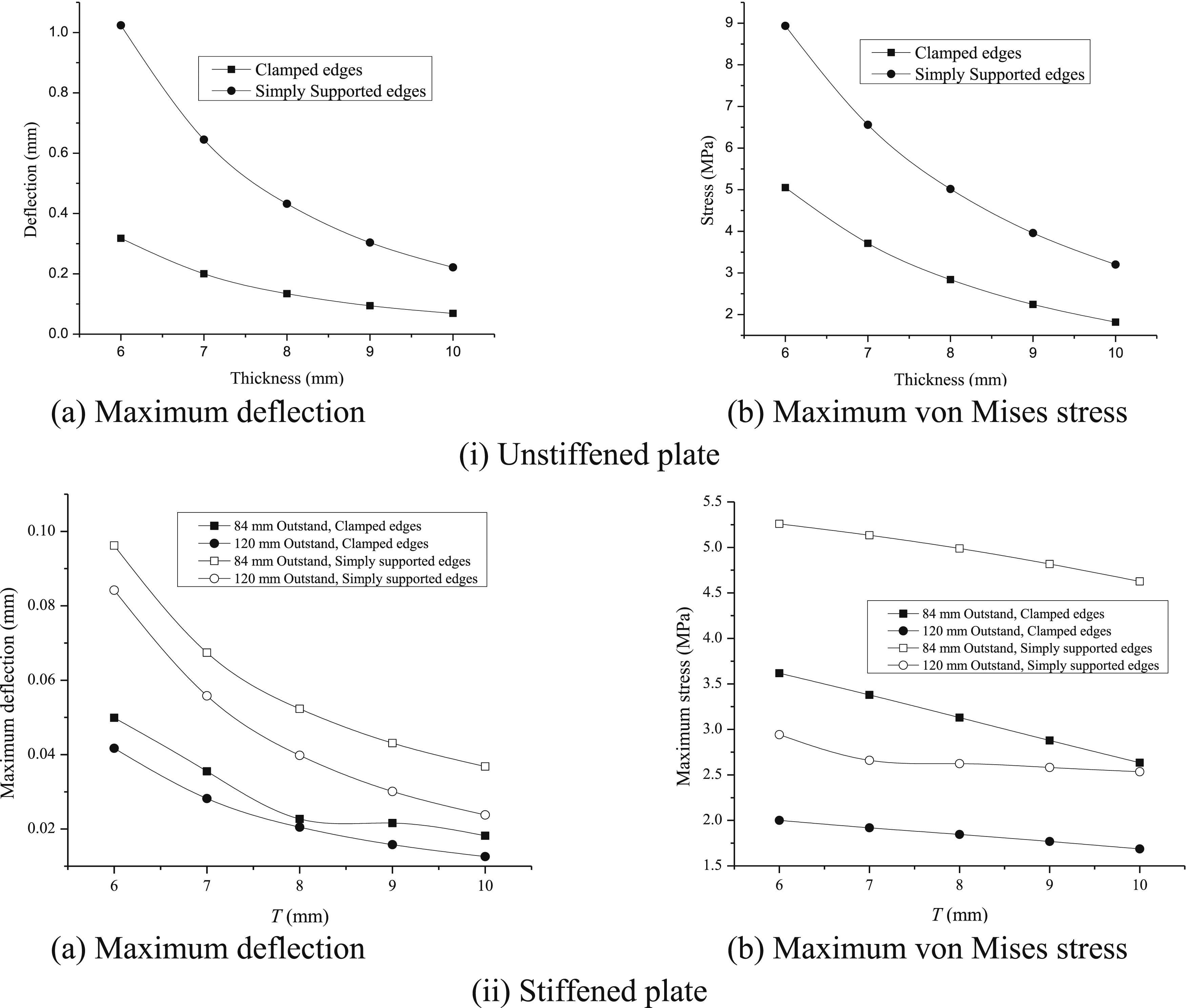
The results of deflection and stress are decreased with the increment in the thickness of the plate for unstiffened as well stiffened plates. The decrement is about 10 times and 2 times for deflection and stress, respectively after stiffening the plate structure. The decrease in results of stiffened plates having 120 mm outstand decreases with the thickness of primary plate compared to stiffened plates having 84 mm outstand. This may be due to having more mass at the centre in case of stiffened plates having 120 mm outstand.
Hydrostatic load
The hydrostatic load is applied on unstiffened plates of thicknesses 6 mm, 7 mm, 8 mm, 9 mm, and 10 mm for both the boundary conditions. The results of deflection and stress are demonstrated in Figure 9. The results are following the same pattern as in the last case where uniformly distributed load was applied. It is observed from the figure that due to the hydrostatic load the response of the plates (unstiffened and stiffened) are increased compared to static load. The results are increased by about 5 times for both the unstiffened and stiffened plates. The results of deflection and stress are decreased by about 10 and 2 times, respectively, when plate is stiffened, subjected to hydrostatic loading. Results by varying the thickness of plate subjected to HSL.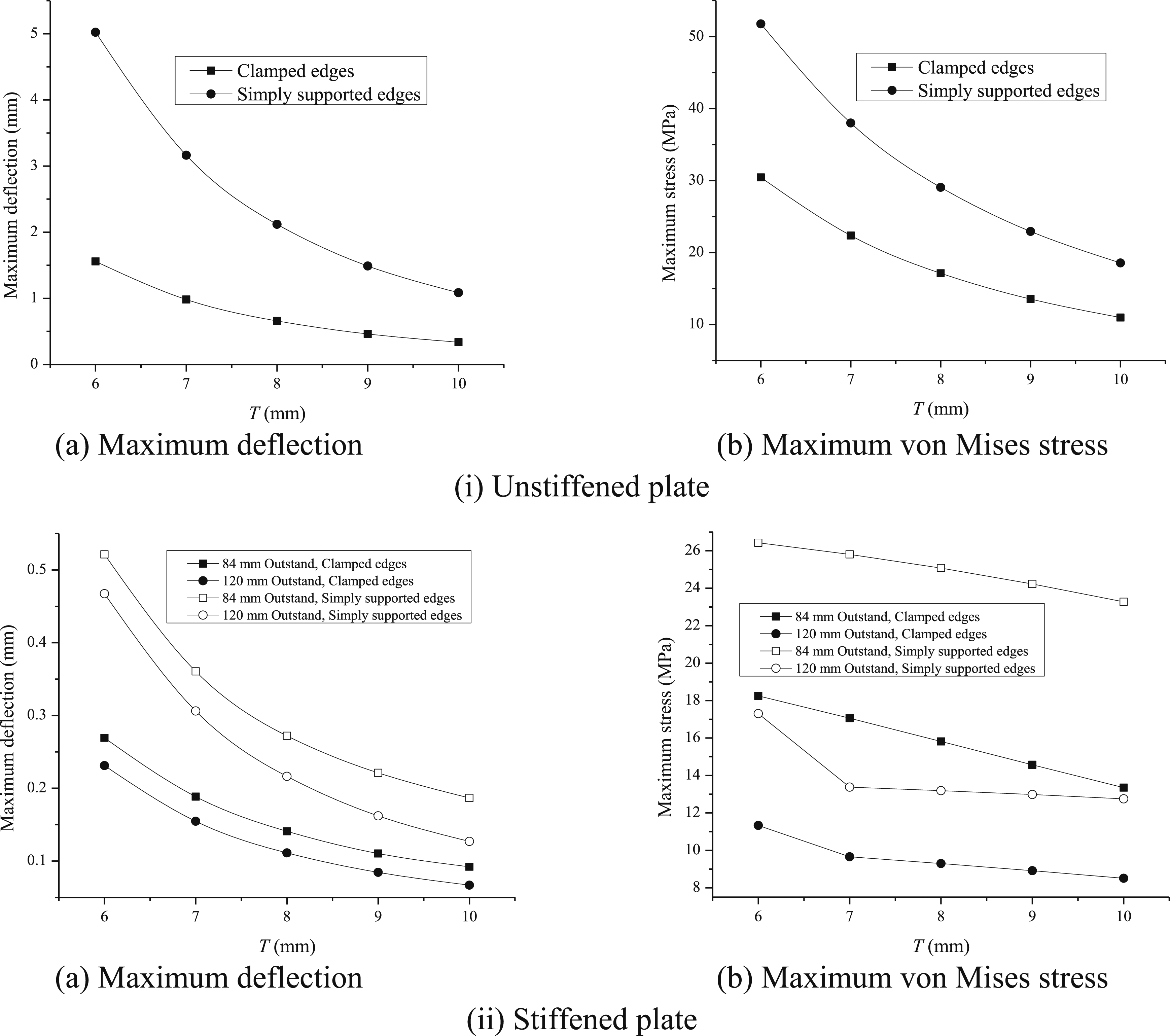
Dynamic analysis
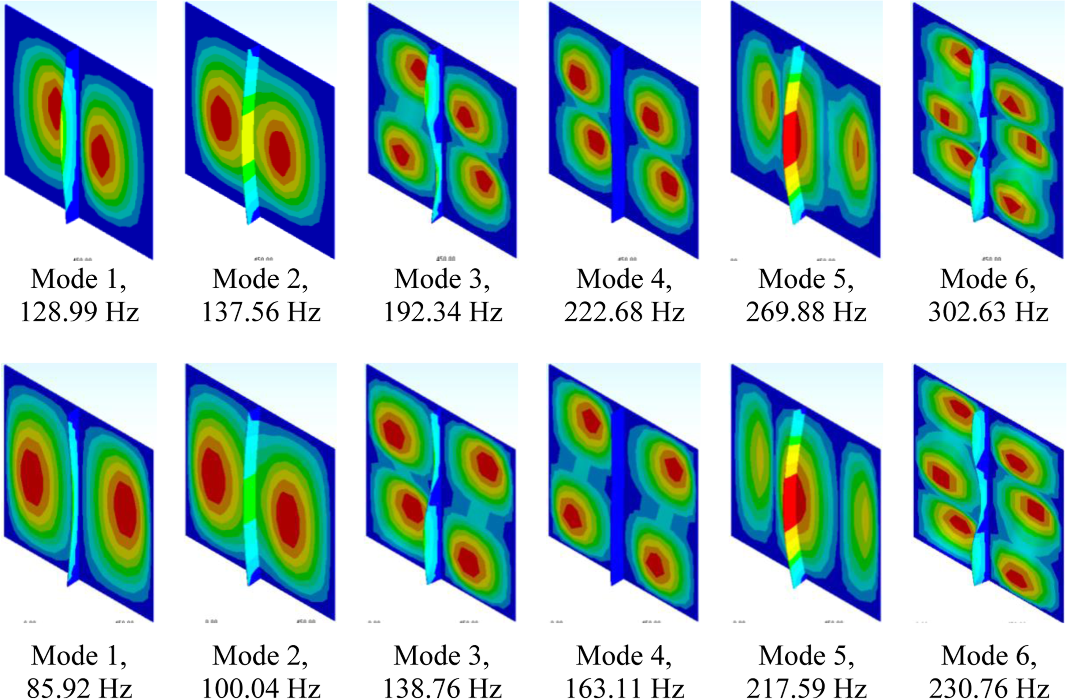
Figures 10 and 11 demonstrate the mode shapes of first six modes of unstiffened and stiffened plates, respectively, for both the boundary conditions. Only first six modes are demonstrated based on the mass participation factor, which is more than 90% in this case using these modes. Figure 12 shows the first six modal frequencies of square clamped and simply supported unstiffened plates of 10 mm thickness. The frequencies for the simply supported plate is lesser compared to clamped plate. Mode shapes of first six modes, unstiffened. (i) Clamped boundary condition. (ii) Simply supported boundary condition. Mode shapes of first six modes. (i) Clamped boundary condition. (ii) Simply supported boundary condition. First six modal frequencies of unstiffened plate.

Now, to enhance the dynamic response of the plate, it is stiffened following the specifications of Indian Standard Codes. The fundamental frequency is plotted against the varying thickness of plate as shown in Figure 13. Fundamental frequency of plates of different thicknesses. (a) Unstiffened plates (b) Stiffened plates.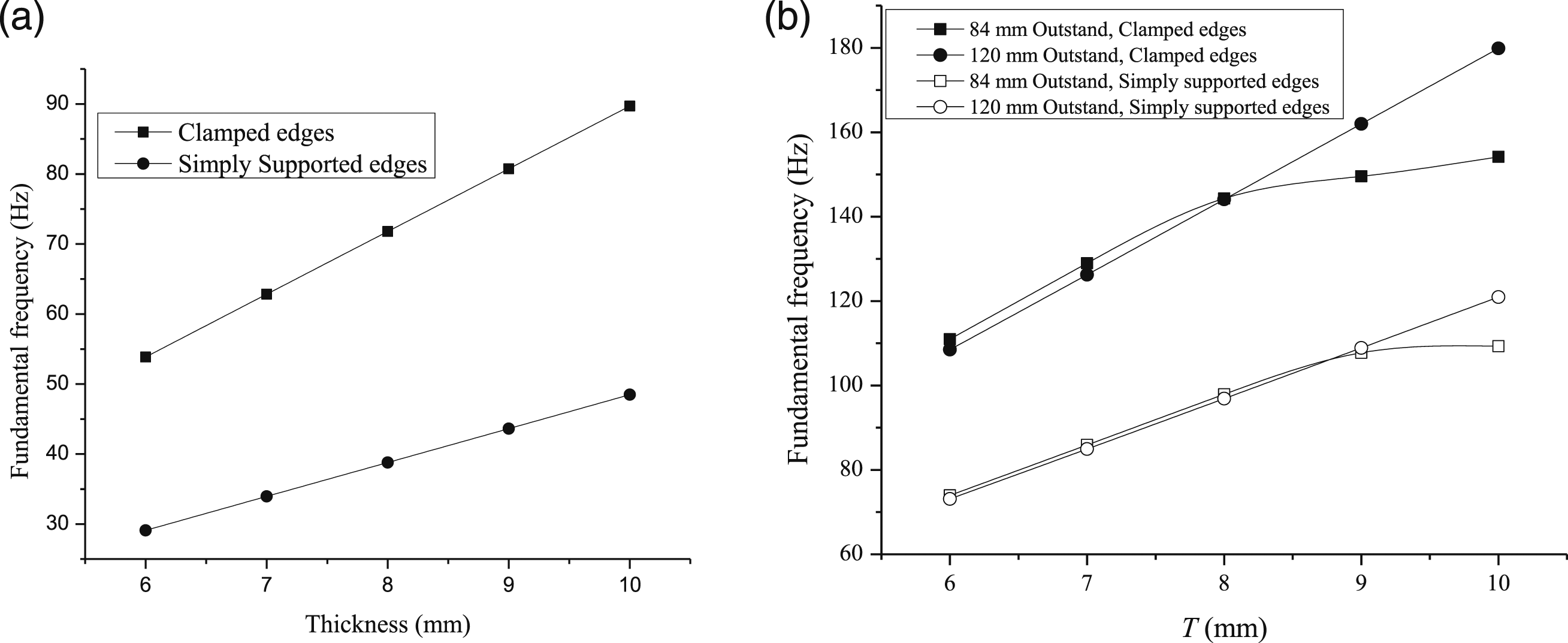
Natural frequencies (Hz) of plates.
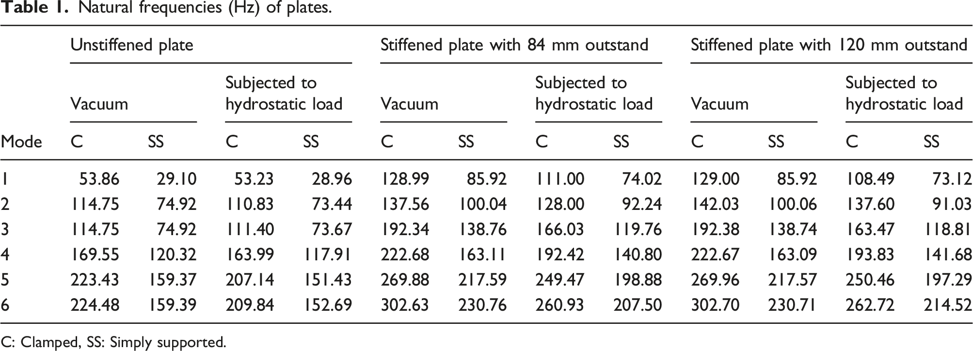
C: Clamped, SS: Simply supported.
Due to the influence of fluid, the frequency decreased and which has to be increased as the influence of low frequency is somehow more compared to high frequency. The mode shapes in other cases are not demonstrated as the contours of mode shapes will be similar to the previous one.
Comparison between unstiffened and stiffened plates
In this section, the results of plates subjected to different loadings are compared, and the response of unstiffened and stiffened plates are also compared. These have been enhanced after stiffening the plate structure even if the same or lesser volume of material is utilised. In the present study, the enhancement due to stiffening of plate looks small as the amount of external load is used so, but in the practical scenarios the stiffening of plate keeping the almost same volume of material would be noticeable.
Figure 14 shows the results of deflection and stress subjected to uniformly distributed load (UDL) and hydrostatic load (HSL). It is observed from the figure that due to the HSL, the effect of deflection and stress have been increased. The results of frequencies are not demonstrated in form of figure as it is showing the same pattern, i.e., the frequencies have been decreased due to the influence of hydrostatic loading. Hence, the plates have to be strengthened against the static loading. For this, plates are stiffened by stripping material from the plate as per the IS (Indian Standard) Codal provisions.
33
Response of unstiffened plate subjected to UDL and HSL. (a) Maximum deflection (b) Maximum von Mises stress.
The results of comparison between unstiffened and stiffened plates are shown in Figures 15 and 16 for plates subjected to UDL and HSL, respectively. The results of stiffened plates are plotted compared to results of unstiffened plates of varying thicknesses. The stiffened plate having length l
s
1 m, outstands o
s
84 mm and 120 mm and thickness t
s
6 mm are considered for this comparison, which has the smallest volume among all stiffened plates, also significantly lesser than the unstiffened plates. It is observed from the figures that when plate is stiffened the effect of loading is decreased. The results of deflection are about 13 to 24% and 14 to 25% for simply supported and clamped plates subjected to UDL and HSL, respectively. The results of stress are also decreased in most of the cases but some cases the stress has been increased but not significantly. Lastly, the fundamental frequency is enhanced when the plate is stiffened. The results of fundamental frequency are about 120 to 210% and 123 to 218% for simply supported and clamped plates subjected to UDL and HSL, respectively. The pattern of results subjected to UDL and HSL are found to be similar but may vary if the intensity of load is increased, which will definitely in the practical scenario. Response of plates subjected to UDL. (a) Maximum deflection (b) Maximum von Mises stress. (c) Fundamental frequency. Response of plates subjected to HSL. (a) Maximum deflection (b) Maximum von Mises stress. (c) Fundamental frequency.

The importance of carrying out comparison between unstiffened and stiffened plates is to find the effectiveness of such structures which are subjected to static and dynamics forces throughout its life span. From the above results and discussion, it is concluded that the response of stiffened plate is significantly enhanced even if the lesser amount of material is investigated in modelling of stiffened plate compared to unstiffened plate.
Conclusions
The analysis has been carried out to determine the response of unstiffened plate and stiffened plate structures. The response is recorded and presented subjected to uniformly distributed load and hydrostatic load. The comparison has been also done between unstiffened and stiffened plates by keeping almost same volume of material between the two. Based on the static and dynamic analyses carried out, the following conclusions have been drawn: (i) Deflection at the centre of unstiffened plate is maximum. The stress at the edges and at the corners is maximum for clamped and simply supported unstiffened plates, respectively. (ii) Deflection and stress in stiffened plates are lesser compared to unstiffened plates. The maximum deflection and stress appears on both sides of the stiffener and at the bottom of the stiffener, respectively. (iii) The dominance of hydrostatic load on the plates is significantly more than uniformly distributed load. (iv) The minimum thickness as specified by the Indian Standard Codal provision as 6 mm and outstand as 84 mm and 120 mm for E250 grade steel is considered. The results of both the stiffened plates are almost same. (v) There is enhancement of results after stiffening of the plate. This enhancement is quite more when plates are subjected to hydrostatic load. (vi) The study also lies in the practical feasibility and cost effectiveness of stiffened plate. For modelling of stiffened plate in actual, the secondary plate or stiffener is attached to the main plate using welding which will account for practical feasibility. The lesser amount of material is utilised for the modelling of stiffened plate with better response as well and will account for cost effectiveness.
Footnotes
Declaration of conflicting interests
The author(s) declared no potential conflicts of interest with respect to the research, authorship, and/or publication of this article.
Funding
The author(s) received no financial support for the research, authorship, and/or publication of this article.