
Abstract
In the present study, a simulation driven PID controller gain estimation methodology is proposed. For simplicity, a cantilever beam is used as a dynamic system and it is excited by using an unbalanced oscillating mass. The vibration is measured with the help of patch type piezoelectric vibration sensor. To provide the actuating force at the free end of the cantilever beam, a rack and pinion type actuator is designed and developed. First the modal parameters are evaluated and subsequently state space model is developed. The initial values of PID gains are estimated using state space and feedback controller designed on Simulink software. The initial gain values are tuned according to physical cantilever beam system. Finally, the vibration results are compared for with and without active vibration control methods as well as before and after the PID gain tuning. The results show that the use of proposed methodology to control the vibration actively using a simulation driven designed PID controller is effective and less time consuming as it gives initial guess of PID gain values.
Introduction
The oscillation or movement of an object or structure around a reference point is referred to as vibration. Depending on the situation, vibration can have both beneficial and detrimental consequences. In mechanical systems, vibration control refers to the methods for reducing or eliminating undesired vibrations. Uncontrolled vibrations can have unfavorable effects, even yet regulated vibrations are necessary for many uses, including industrial machinery and musical instruments. Vibration needs to be controlled because of its negative effects. This can be done by changing the system’s structure to change its dynamic behavior as well as by using passive, active or semi-active control techniques. In active vibration control (AVC), the PID gain estimations is a very important aspect. The PID gain can be estimated by different techniques available in the literature such as pole placement techniques, optimal control techniques etc. Ram, & Mottershead 1 used receptance method for pole placement to control the vibrations. Mottershead et al. 2 used pole-zero placement cum measured receptances for AVC. Kumar & Narayanan 3 used linear quadratic regulator controller for most favorable location of piezo sensor and actuator pairs. Bruant et al. 4 performed AVC for beam equiped with piezo sensor and actuator using modeling and simulation. Gaudenzi 5 also studied piezoelectric devices for active control of beam vibrations. Xu and Koko 6 showed the results of vibration suppresion of cantilever beam using FE modeling in ANSYS for actviely control the vibration. Further, the impact of sensor and actuator position was also investigated. In addition to expanding on the work of Xu and Koko. 6 An optomal method for positioning piezo sensor and actuator pairs on laminated composite plates for mitigating the vibration. 7 Khot et al. 8 studied AVC with PID controller for cantilever beam vibration control. Khot et al. 9 also designed the best controller utilizing the Linear Quadratic Regulator controller using state feedback control by reducing a full model of a cantilever beam. Jaiswal & Prakash 10 did comparative study between classical and modern PID gain estimation approaches. Issa 11 used an arithmetic optimization algorithm to estimate the finest estimates of the PID gains. Doicin et al. 12 studies optimal tuning of parameters of a PID controller for two different case studies. Beam with piezoelectric-patches was also utilized by Singh et al. 13 and modal control techniques were used. Karagulle et al. 14 suggested a method based on ANSYS simulation for AVC for cantilever equiped with piezo sensor and actuator.
Based on the literature, it has been summarized that the controller requires pre-determined gain values for active vibration control.10,11 However, to perform experiments on-site the structure may give different responses to that pre-determined gain values. This means that the actual gain values should be known. But, during on-site installation of active vibration controller, we don’t have actual gain values of the controller. In that case we cannot take random values of gains because it will take many iterations to match the actual gain values. On the other hand, some advanced control algorithms such as closed loop adaptive control etc. can be used to control the vibration. Thus, choosing controller gain values that can control the vibration actively on-site in a machine is the problem in active vibration control. In the current study, a cantilever beam’s vibration is controlled using piezoelectric sensor, a servo motor cum rack and pinion type actuator and PID controller. The PID gain estimation and vibration control methodology is presented in the next sections.
Methodology
In the current research, a simulation driven PID controller gain estimation methodology is proposed. The proposed methodology can be used to guess initial gain values which can be tuned easily to the actual gain values. In that case, an approximate simulation driven gain values are obtained using modal analysis and state space modelling. The obtained simulation driven controller gains values give the idea to select gain values close to actual values rather than choosing random values of the gain. Thus, it is easy to tune simulated gain values with the actual gain values with less time and effort. Modal analysis of cantilever beam is required to get the modal parameters such as natural frequencies, mode shapes and damping factors of the beam. These modal parameters will be used to generate the state-space model and then determine the PID based feedback controller parameters such as gains. After that the gains will be used to actively control the vibration of a cantilever beam. The detailed methodology is given in Figure 1. Flow diagram of proposed methodology.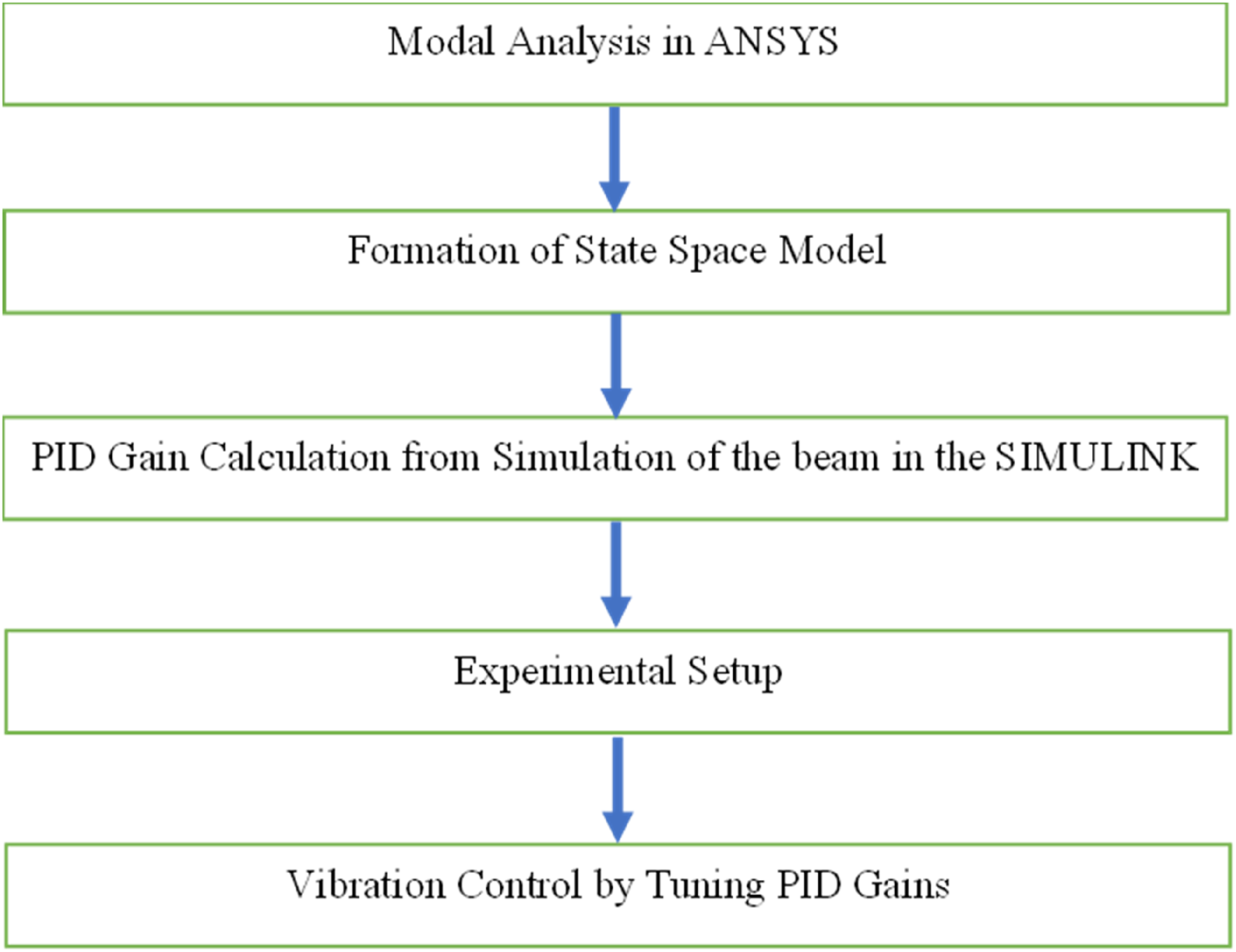
Basically the following steps are performed. Step 1: Modal Analysis of the cantilever beam in the ANSYS. Step 2: Formation of state space model. Step 3: Calculation of PID gains from the AVC simulation in the SIMULINK based on step 1 and 2. Step 4: Experimental setup of cantilever beam with sensor and actuator. Step 5: Vibration control by the tuning of PID parameters.
Modal analysis
The modal analysis is used to estimate modal parameters such as natural frequencies, mode shapes and damping ratios. The governing dynamic equation for multi-degrees of freedom system can be written as;

Since
The eigenvalue problem for the system is expressed as;

The eigenvectors
The modal matrix is formed by assembling the eigenvectors as;

The modal matrix is used to transform the original coordinates into modal coordinates. For MDOF system with proportional damping, the displacement vector

When the normal modes are normalized with respect to the mass, the equation of motion in the modal coordinates will be simplified.
The equation of motion in the modal coordinates are given by;


State-space model formation
Define a state vector X that will be introduced by both displacement and velocity.
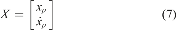
The state space representation is given by the following first order differential equation and output equation;


To find the unknown matrixes in Equations (8) and (9), The MATLAB code is used to get the state space matrices from Modal analysis results and are given in Appendix A.
PID controller gains estimation
After knowing the Matrices A, B, C, and D, state space model is created in feedback loop along with PID controller, sensor, step unit function and scope. This state space feedback control block diagram is created in Simulink software as shown in Figure 2. With the help of this feedback loop simulation, the PID gains such as proportional, integral and derivative gains will be tuned based on controlled output. Simulink Block Diagram for tuning PID gains.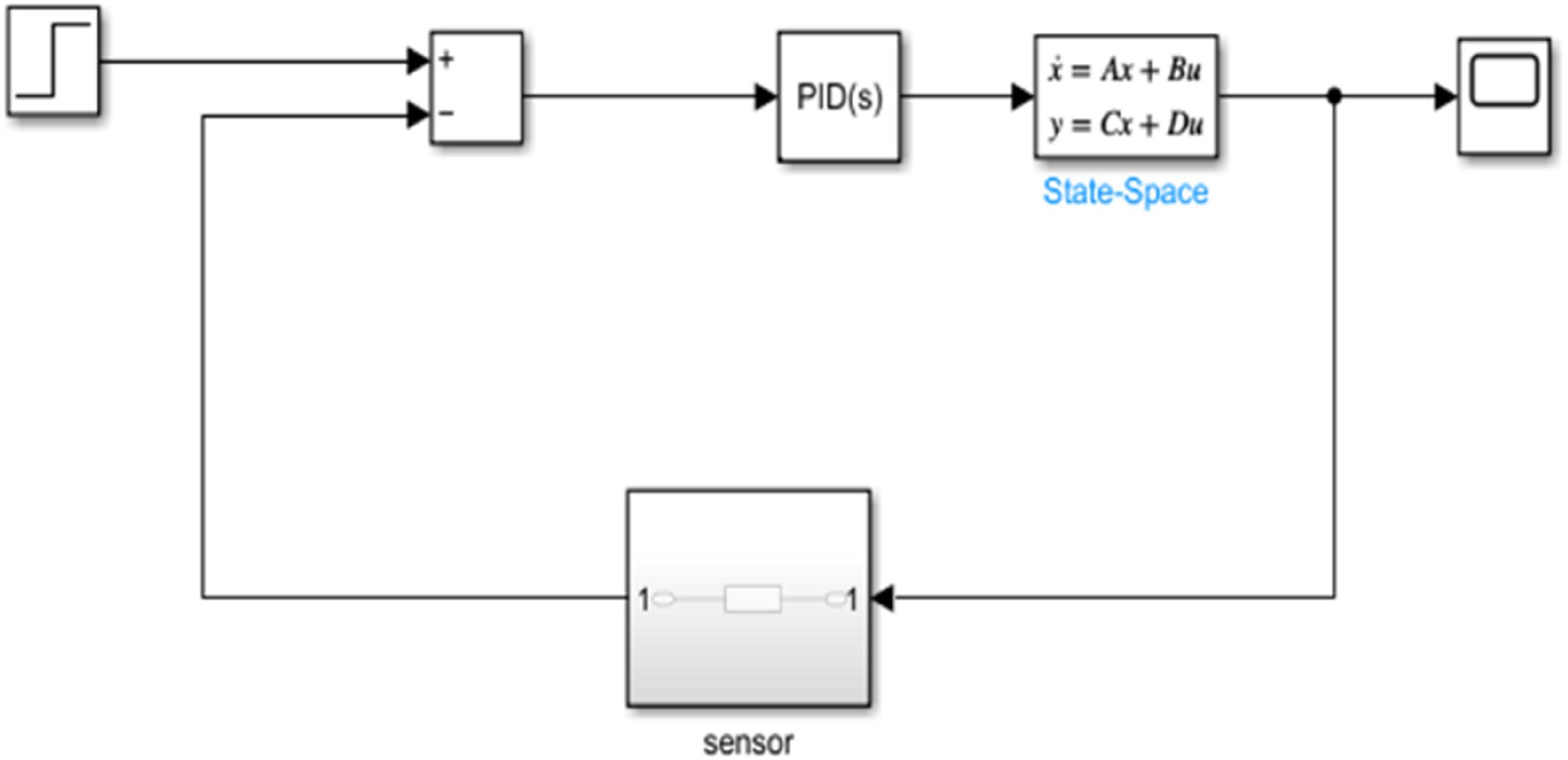
The proportional (P), integral (I) and derivative (D) term are summed to find the output u of the PID controller can be expressed as.
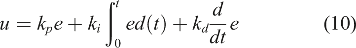
PID controller considers the error signal e as an input signal and generates a controlled signal u. This controlled signal is sent through the state space model which represent the dynamic properties of the beam and control the vibrations of the beam. One branch of this signal is again sent to the Add block as a feedback loop so that we can tune the parameters of the PID controller and get a set of gains.
Experimentation
An experimental setup is prepared to control the vibration of the cantilever beam. For this a stainless-steel beam of Experimental setup.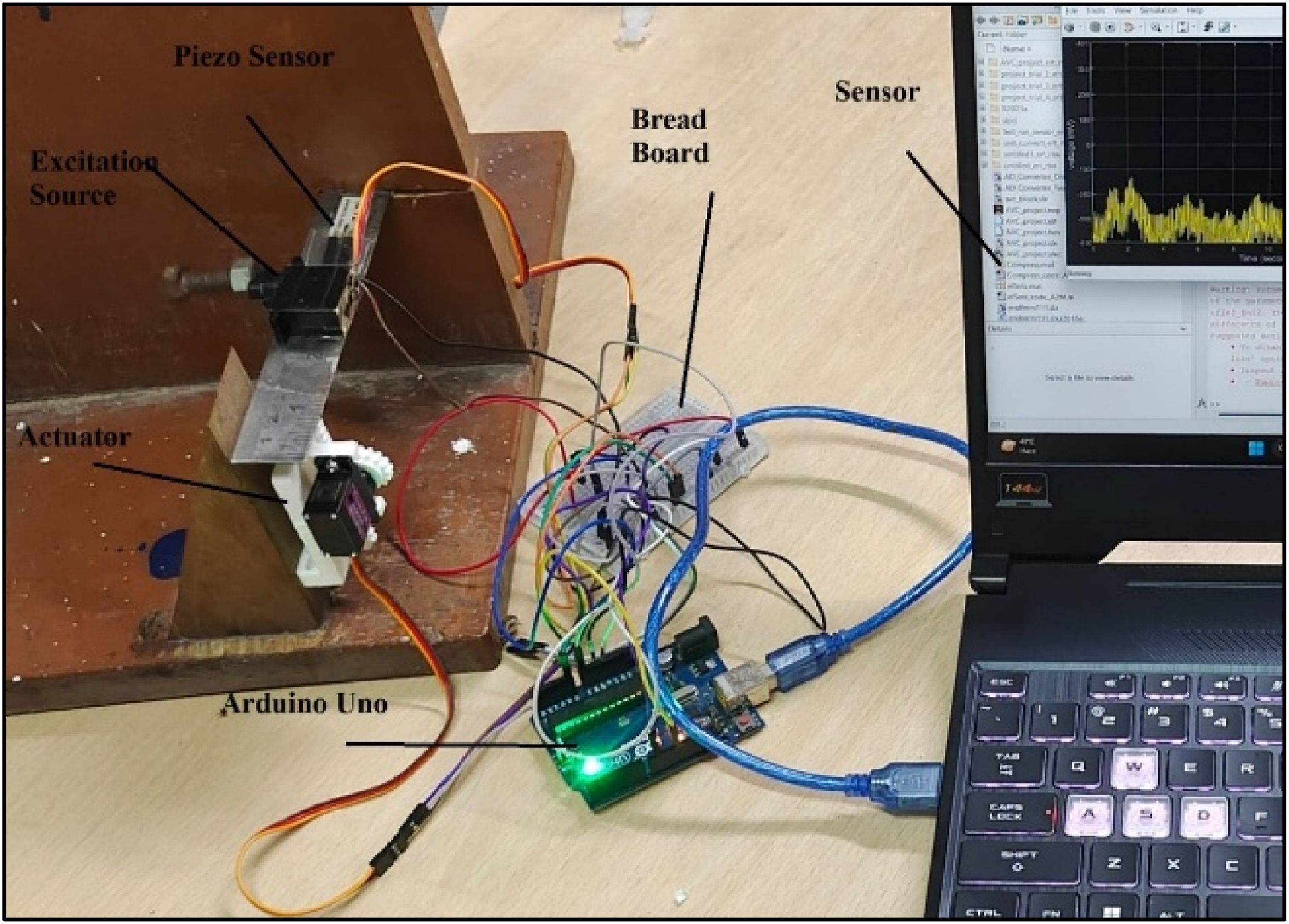
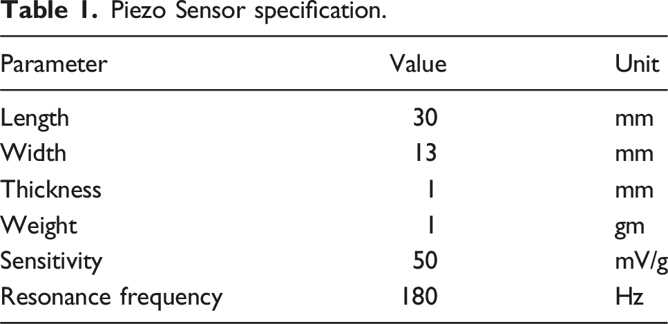
Piezo Sensor specification.
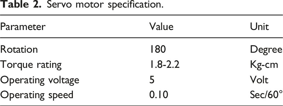
Servo motor specification.
Working principle
When exciting signal is sent to the servo motor from the SIMULINK, beam starts to vibrate. These vibrations will be measured by the piezo sensor in the form of voltage and sent to the SIMULINK, where these signals will be passed through the low pass filter. Low pass filter is used to remove the low frequency noise from the vibration signals. Now filtered signals will be subtracted from the reference signals and send to the PID controller. The PID controller is designed according to the results from the simulation, which is performed earlier. PID controller will process the data and create an actuating signal to control the vibrations. This actuating signal will be sent to the actuator in the form of voltage and the actuator applies an actuating force on the beam through rack and pinion actuator. The residual vibrations will be measured by the sensor again and the whole process is repeated as a feedback loop until the vibrations are controlled. The SIMULINK block diagram is shown in Figure 4. We have taken sine wave as a reference signal here. So, the constraint output of the PID will be like sinewave. Initially the gain of PID controller will be taken from the simulation and then tuned to get the better results. SIMULINK block diagram for physical System.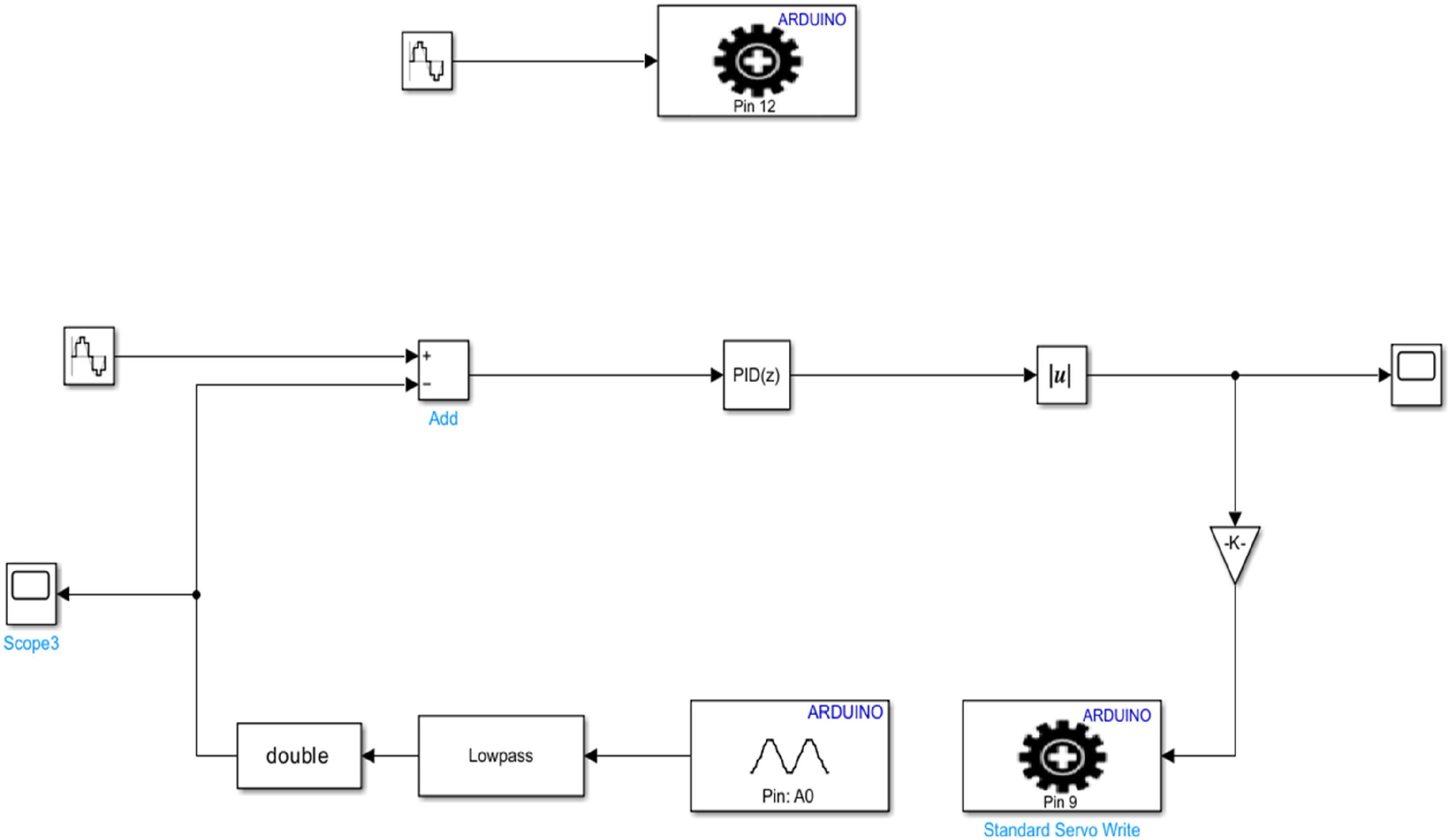
Results and discussion
The methodology as proposed in section 2 is formulated and discussed in subsequent sections for example section 3 for modal analysis, section 4 for state space formulation, section 5 for PID gain estimation and section 6 for experimental work. The results obatined in these sections are now discussed in this section. The modal analysis has been performed to obtain natural frequencies and mode shapes of the cantilever beam selected for this study. These modal parameters have been used to determine space space matrices. For this, modal analysis of the cantilever beam is carried out in ANSYS Workbench. The same cantilever beam as used in experimental work is modeled in ANSYS and modal parameter results such as natural frequencies and mode shapes for the first four modes are estimated and shown in Figure 5. The natural frequencies of first four modes are estimated as 22.67 Hz, 141.92 Hz, 398.02 Hz, and 782.42 Hz. First four modes of cantilever beam.
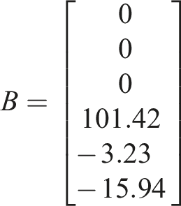
The above modal parameters have been used to estimate the matrices of the state space model matrices as discussed in Annexure A and obatined matrices A, B, C, and D are given below.
The obtained values of state space matrices are given below;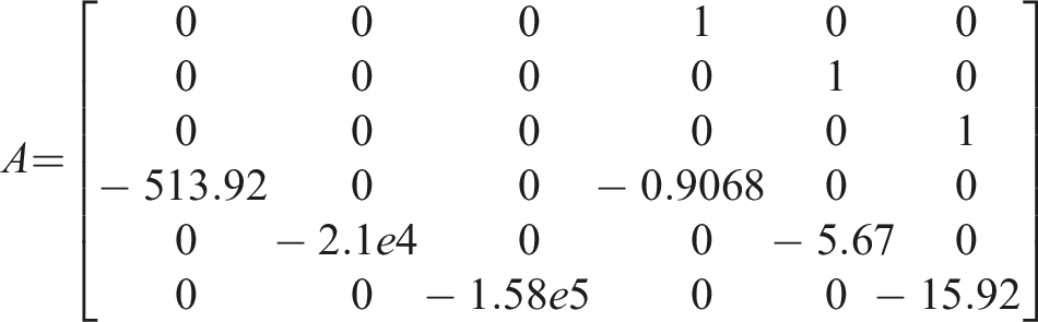


The state space model of cantilever beam with PID controller is now created in MATLAB simulink software utilizing above matrices. Tuning of PID controller is done with the help of this model. The dynamic response of the simulated cantilever beam after tuning the gains is shown in Figure 6 below. Simulated controlled dynamic response of the cantilever beam after PID control.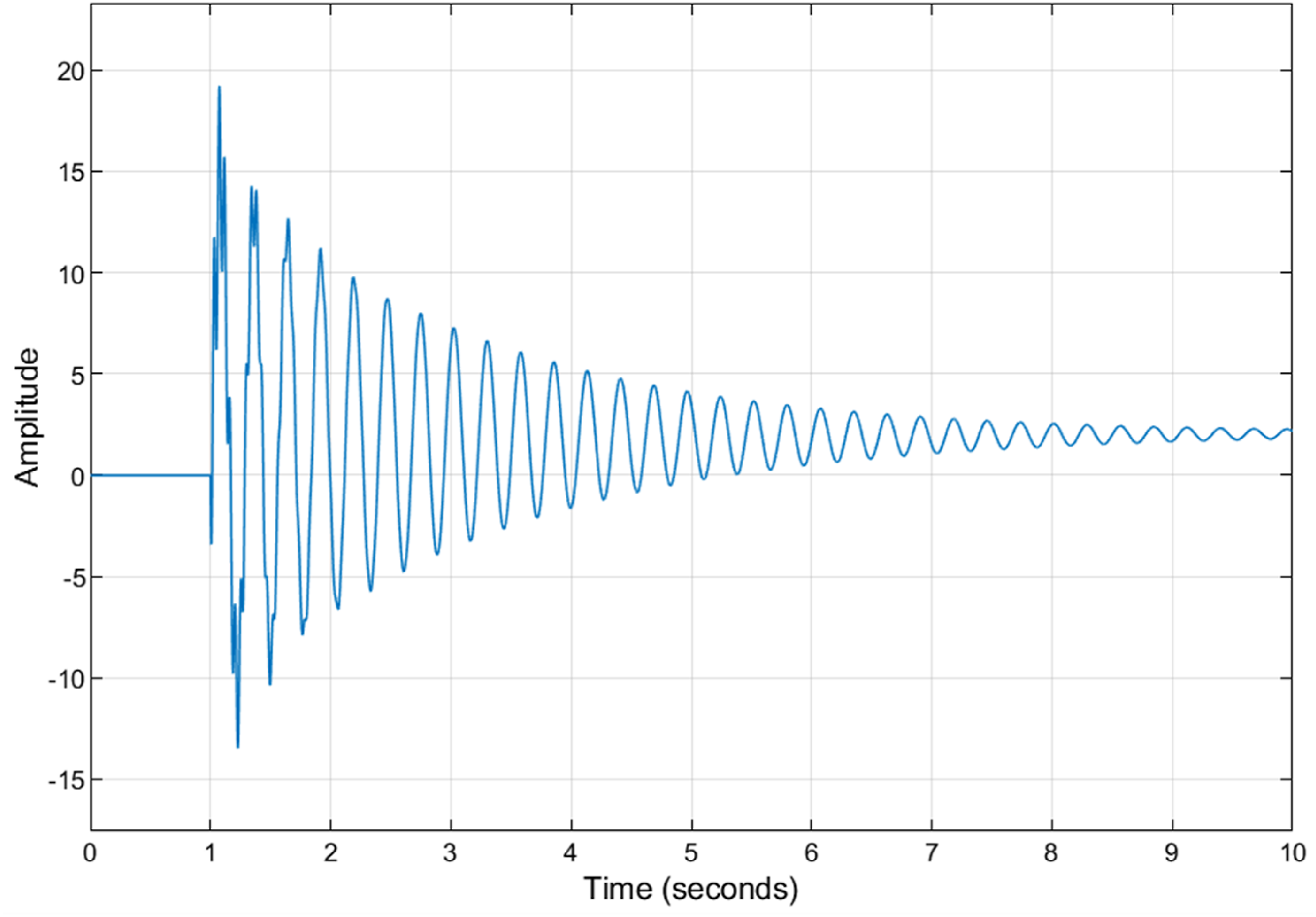
After implementation of simulation and experimentation work, it is observed that the PID gain estimation becomes easy to tune for vibration suppression. The basic CAD model of cantilever beam, the modal analysis and state space model in Simulink software are used to estimate PID gains. For this, the simulation is performed on 50 Hz excitation frequency.
This initial gain values from the simulation of the beam in ANSYS and SIMULINK for AVC are obtained as proportional gain, P = 8, integral gain, I = 0.15, and derivative gain, D = 3.
Thus, the initial estimation of gains used for experimentally suppression of vibration actively. However, a comparison is provided in Figure 7(a) for uncontrolled and controlled cases. Figure 7(a) clearly shows that the vibration in the beam is not controlled properly using simulated PID gain values. This is because the approximate models were used for simulation as well as may be some error in instrumentation part. For this, we need to tune the PID gain for actual experiment to control the vibrations in the beam. Comparison of uncontrolled and controlled vibration (a) using simulation gain (b) using tuned gain in experiment.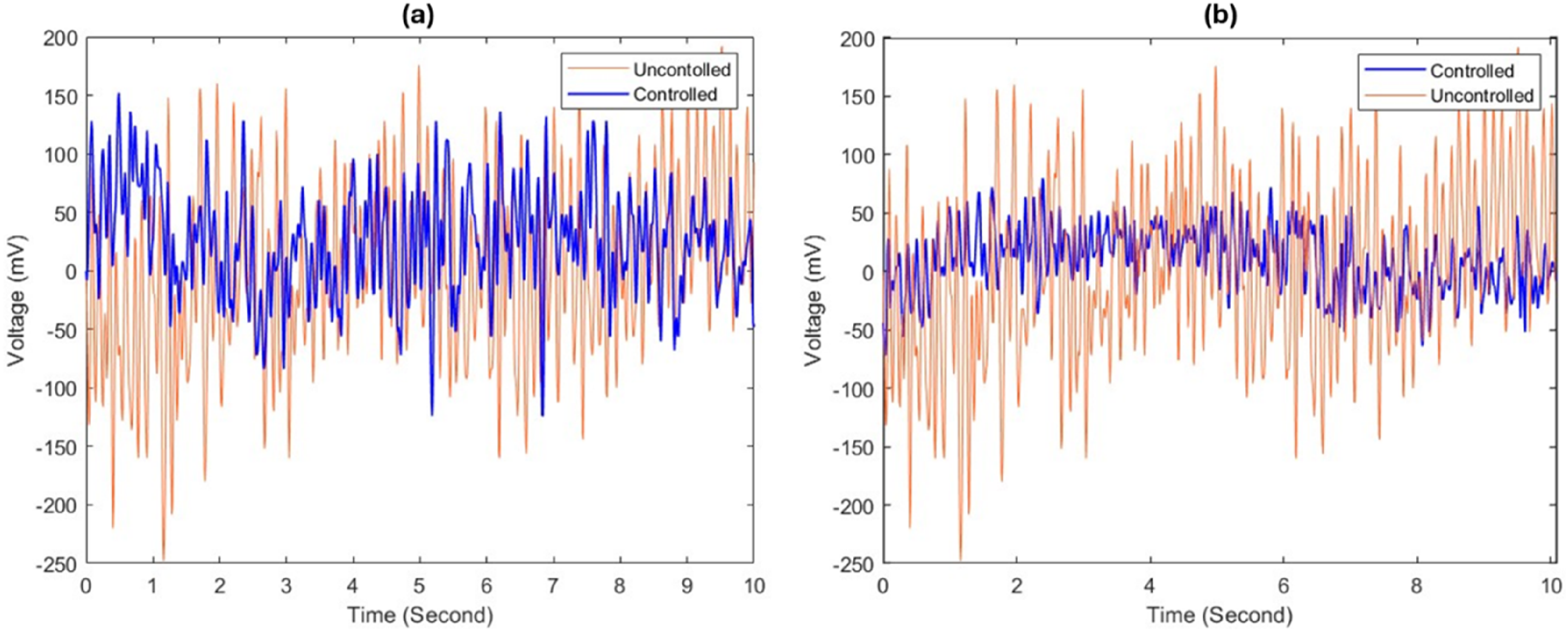
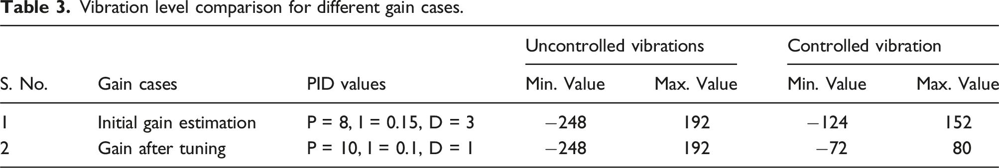
After tuning the gains of the PID controller using simulink model shown in Figure 4, we get some values of PID gains. These gains significantly decreases the vibration of the cantilever beam as shown in Figure 7(b). The values of the gains are the proportional gain, P = 10, integral gain, I = 0.1, and derivative gain, D = 1. Figure 7(b) clearly shows the comparison between uncontrolled vibration level and controlled vibration level after tuning PID gains. The RMS value comparison is shown in Figure 8, which shows the vibration reduction after using PID controller. The uncontrolled vibration level was 126.41 mV and after initial gain obatined by simulation, the controlled vibration level is estimated as 68.21 mV. But this is the initial guess obtained using modal analysis and state space modelling or simulation. After PID gain tuning, the controlled vibration level is obtained as 36.39 mV. Thus, the vibration level after initial gain is reduced by 46.04% and after gain tuning it is reduced by 71.21%. The vibration level comparison is also given in Table 3, for initial gain and after tuning the gain. Which shows that the simulation driven initial estimation is helpful for tuning the required PID gain values for actual experiment. RMS value comparison for different cases. Vibration level comparison for different gain cases.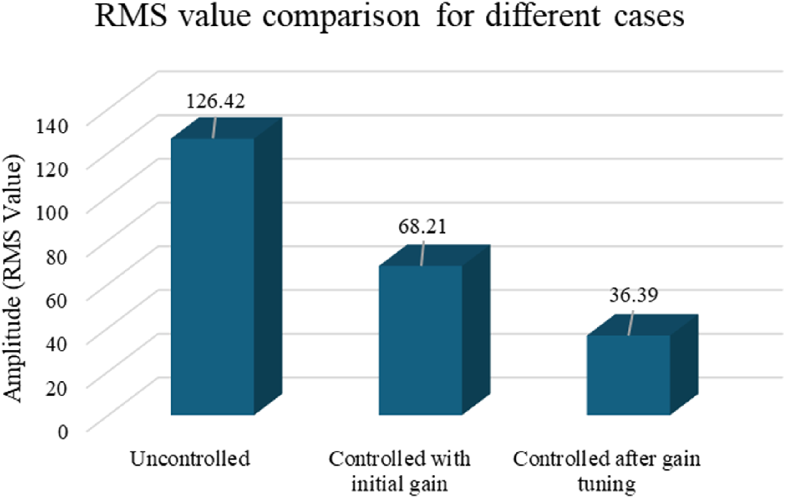
Conclusions
In present study, an AVC experiment for vibration control of cantilever beam is demonstrated using initial tuning by simulation through ANSYS and SIMULINK software. PID gains are calculated based on the modal analysis and state space modeling. In the experimental setup a piezo sensor and excitation source are attached to the the cantilever beam. The vibration in the beam is measured by the piezo sensor. A PID controller is designed and implemented on the cantilever beam. After tuning the values of the gains are obtained as proportional gain, P = 10, integral gain, I = 0.1, and derivative gain, D = 1, which shows the vibrative is reduced signicantly by uisng simulation driven AVC method. The vibration level after initial gain is reduced by 46.04% and after gain tuning it is reduced by 71.21%. The vibration can be further reduced by using desired reference signal selection or more accurate modelling of the physical system.
Supplemental Material
Supplemental Material - Simulation-driven PID controller gain estimation for active vibration control
Supplemental Material for Simulation-driven PID controller gain estimation for active vibration control by Om Prakash Meena and Naresh K. Raghuwanshi in Noise & Vibration Worldwide
Footnotes
Declaration of conflicting interests
The authors declared no potential conflicts of interest with respect to the research, authorship, and/or publication of this article.
Funding
The authors received no financial support for the research, authorship, and/or publication of this article.
Supplemental Material
Supplemental material for this article is available online.