
Abstract
In order to improve the ride comfort of the passenger vehicles, an improved MR damper is designed. The magnetic pole of the damper is sinusoidal, whose effective length can be controlled by the magnetic field. In this way, the flow area of MR fluid can be controlled. The mechanical analysis of the proposed MR damper is carried out and the theoretical analysis results show that the proposed damper can meet the damping force requirements of vehicles under various driving conditions. Half car models are established, simulation analysis is carried out under random excitation, the evaluation parameters such as body acceleration and pitch angle are analyzed comprehensively. The results show that the proposed damper is more conducive to improve the ride comfort of the vehicle.
Introduction
The main function of automobile suspension is to support the body, isolate vibration so that to improve the riding comfort. Suspension is mainly divided into passive suspension, semi-active suspension and active suspension according to the type of the damper. Passive suspension has been widely used because of its simple structure, reliable performance, low cost and no additional energy input. Through a lot of experimental analysis and optimization design, the optimal damping characteristics of suspension are obtained as shown in Figure 1.
1
Optimization of damping characteristics based on piston velocity.
According to the optimization results, we can see that the damper should have large damping coefficient at low velocity and small damping coefficient is required at high velocity. Under different road conditions, the requirements of damping force are not the same. Much more, there is a sudden change point of damping coefficient at a specific velocity, which corresponds to rapid steering.
However, because the stiffness and damping of passive suspension are not adjustable, it can not guarantee to achieve the optimal vibration reduction effect under various working conditions, and it is difficult for passive suspension to obtain good ride comfort and handling stability at the same time. As to the defects of passive suspension, active suspensions have been proposed.2–5 By adjusting the damping force according to the driving conditions, excellent driving performance with active suspensions can be achieved. However, active suspension needs a lot of energy, and more sensors are deployed. And it is easy to cause performance deterioration if the control is not proper. Semi-active suspension takes into account the advantages of passive suspension and active suspension, so it has been widely studied and developed rapidly.
With the development and maturity of magnetorheological technology, the MR damper, which with simple structure, fast response, low power consumption, has become one of the commonly used actuators in semi-active suspension.6–10 Generally speaking, there are four working modes of MR damper, that is, shear mode, flow mode, squeeze mode, and pinch mode. In the shear mode, when two plates move with each other, the shear stress is produced. With magnetic filed, when the magnetorheological fluid flows through two fixed parallel plates, the pressure drop occurs. In the squeeze mode, the direction of the applied force is parallel to the magnetic field. The pinch mode can be realized through non-magnetic ring to separate the magnetic poles. Then the damping force can be controlled by controlling the magnetic field intensity to change the flow rate of MR fluid. At present, most of the magnetorheological dampers used in automobile suspension are shear mode and flow mode, while the research on pinch mode is very few. The research results show that there is a sudden change of damping force in the low velocity region of piston in shear mode and flow mode. 11 For this problem, Choi S. B. et al. proposed that the damping force characteristics in low velocity can be effectively improved by adding bypass holes to the piston. 12 However, it is difficult to adjust the point of slope breaking. Bo Gyu Kim et al proposed a novel type of MR damper with pole shape function to realize the control of piston damping at low velocity and high velocity. 13 However, due to the unequal forces around the piston, theoretically speaking, the damper is easy to be worn or stuck in the working process.
Therefore, based on Bo Gyu Kim’s research, this paper further improved the damper structure, so that to improve the damping characteristics in low velocity region and adjust the position of the slope breaking point, and the expected damping characteristics are shown in Figure 2(a) and the detailed structure of the damper is shown in Figure 2(b). The important improvement lies in one side of the magnetic pole of the proposed damper is machined into a sinusoidal shape, and matched with the corresponding magnetic shielding ring. Due to the symmetry of the designed magnetic pole and magnetic shielding ring about the axis, with the piston rod as the support point, the equivalent torque formed by the force acting on the piston surface can be balanced theoretically. The mechanical model of the proposed damper is analyzed, and the relationship between damping force and control magnetic field strength and piston velocity is studied through theory. Finally, the proposed damper is applied to the half vehicle model, and the performance is analyzed by simulation. (a) Damping force characteristics of the proposed Mr damper, (b) structure diagram of the proposed Mr damper.
Operating principle of the proposed damper
The structure of the proposed damper is shown in Figure 2(b). The damper is mainly composed of piston, piston rod, floating piston and piston barrel. And it is divided into upper and lower chambers by piston. The function of the accumulator, which consists of a floating piston and an air chamber below, is to prevent the decline of magnetorheological effect by separating air and magnetorheological fluid. Prevent piston from jamming, which is due to the volume change caused by the piston rod in and out. It can be seen from Figure 2(b) that the piston has a main orifice. The upper and lower parts of the piston are respectively equipped with a pair of magnetic poles made of magnetic materials and a magnetic shielding ring made of paramagnetic materials. The effective length of the magnetic pole can be controlled by isolating the magnetic field through the magnetic shielding ring, so that to adjust the damping coefficient. The piston has two rectangular symmetrical bypass orifices, which its opening and closing can be controlled independently by secondary coil, so that to control the position of the slope breaking point. The results of the finite element analysis show that the magnetic field intensity of the main channel and the side channel can be controlled independently and almost have no influence on each other.
Damping force is generated as the magnetorheological fluid flowing through the orifices due to the piston movement. The total damping force is composed of the field-dependent and viscosity damping forces. The force of field-dependent can be controlled by the intensity of magnetic field, and it increases with the increase of the magnetic field. If the damping force of field-dependent is large enough, the magnetorheological fluid can not flow due to blockage. The opening and closing control of bypass orifice can be realized by this principle. For the main orifice, as one side of the magnetic pole and the magnetic shielding ring are processed into sinusoidal shape. Therefore, the length of the effective magnetic pole along the circumference is different, and under the same magnetic field intensity, the blocking phenomenon is more likely to occur at the position with longer effective magnetic pole length. While it is not easy to occur where the effective magnetic pole is short. So the size of the blockage area can be controlled by the magnetic field of the main orifice, so as to change the effective flow area of the main orifice, as shown in Figure 3. At the same piston velocity, the velocity of MR fluid flowing through the orifice is different due to the different effective flow area of the main orifice. In this way, the damping coefficient can be controlled. Diagrame of effective flow area of main orifice. (a) No magnetic field is applied to the main orifice, (b) the magnetic field applied to the main orifice is small, (c) the magnetic field applied to the main orifice is large.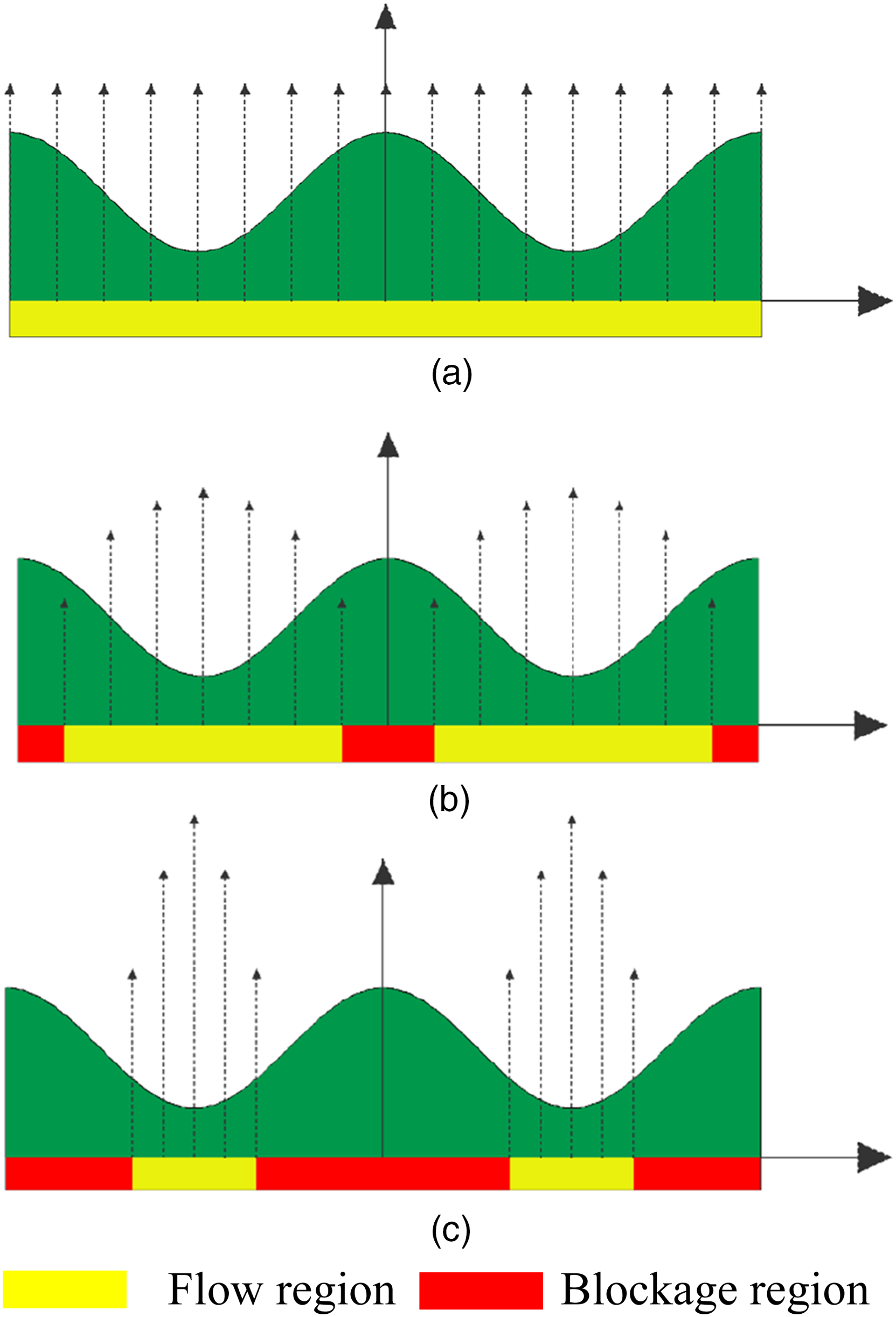
Through the coordinated control of the main orifice and bypass orifice, the damping coefficient and the position of the slope breaking point can be controlled, the requirements of damping force at different piston velocities are realized, and the vehicle handling and riding comfort under various driving conditions are improved. The general matching law of the main and bypass orifices is as follows. When the piston of the damper is at low velocity, the bypass orifice is closed to obtain a larger damping coefficient so that to ensure the handling stability of the vehicle. When the piston is at high velocity, the bypass hole is opened to obtain a smaller damping coefficient to ensure the ride comfort. As shown in Figure 4. Operation relationship of the main and bypass orifices based on piston velocity, (a) low piston velocity with high damping coefficient, (b) high piston velocity with low damping coefficient.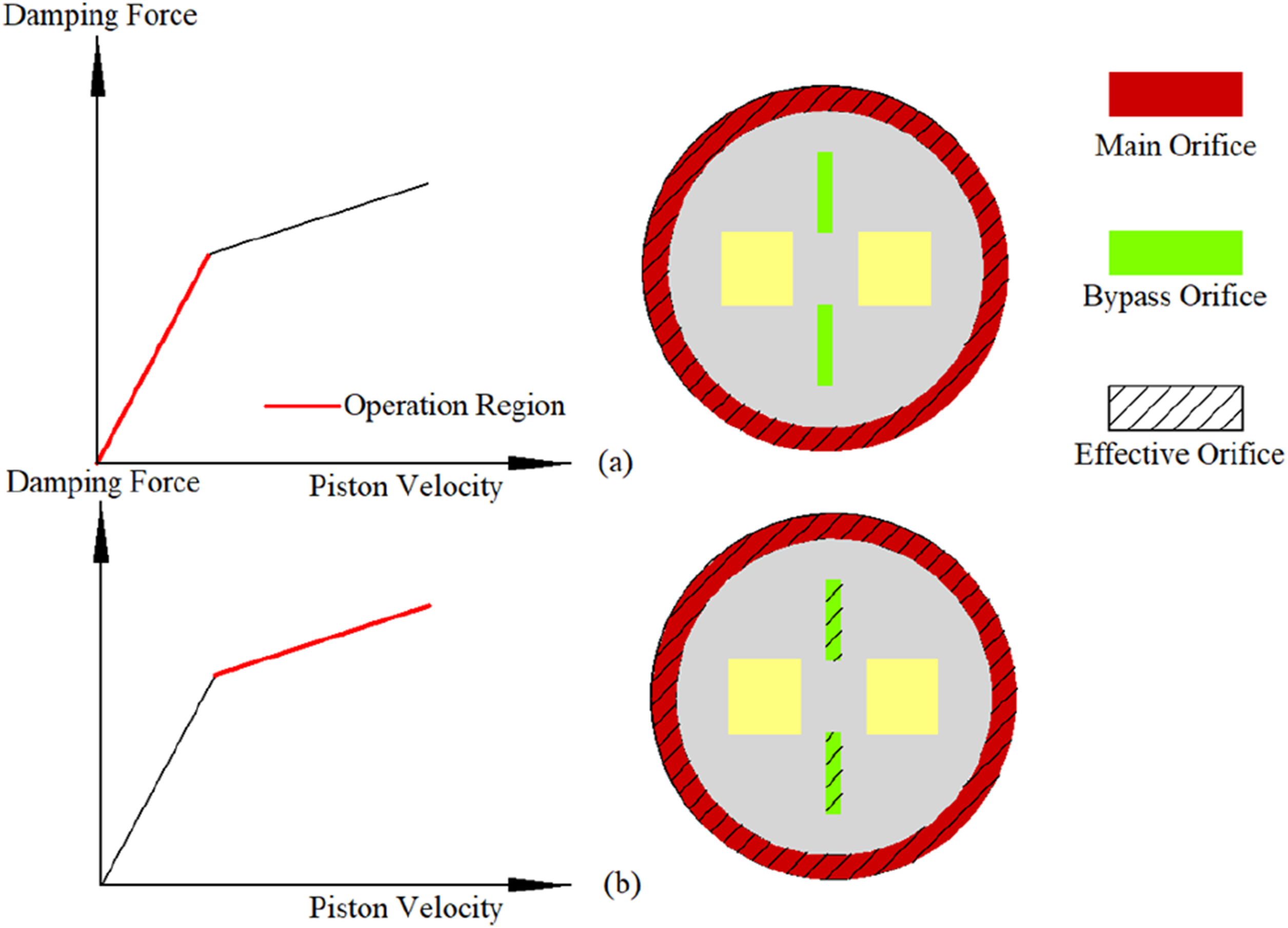
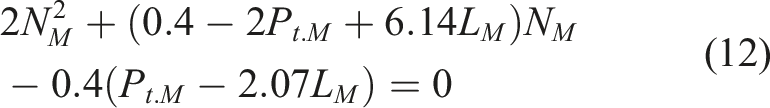
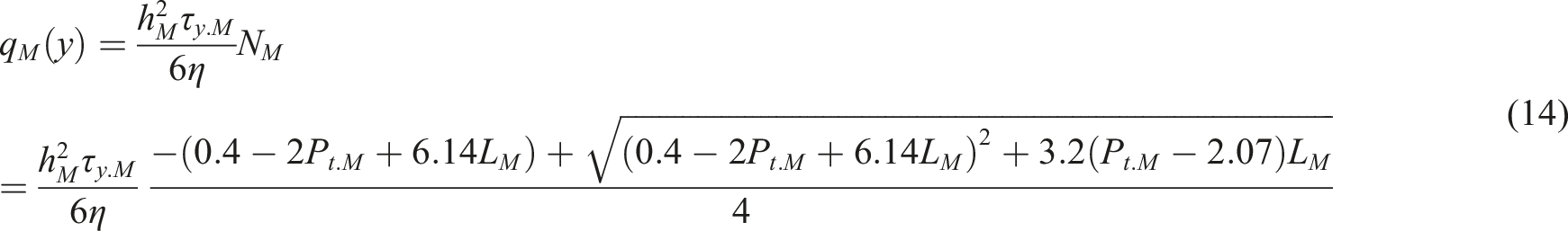
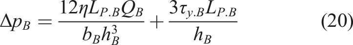
Modeling and analysis of damping force
In order to analyze the relationship between damping force, piston velocity and applied magnetic field, the following assumptions are made: (1) the parallel plate model is used. (2) The MR fluid is incompressible. (3) The flow is completely laminar. Usually, Bingham model is used to analyze the mechanical behavior of MRF. And the damping force is composed of viscous and field-dependent damping force. When the total stress is greater than the field-dependent yield stress, the Bingham equation can be expressed as
14
:

When the total stress is less than the yield stress related to the magnetic field, the MRF exhibits the characteristics of elastomer as follow:

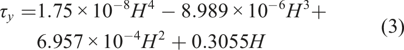
In this paper, based on the magnetorheological fluid (MRF-132DG) of Lord Company, the relationship between the yield stress of MR fluid and the applied magnetic field strength can be obtained according to the official data provided by the company,
15
as shown in Figure 5. Relationship between yield stress and magnetic field intensity of MRF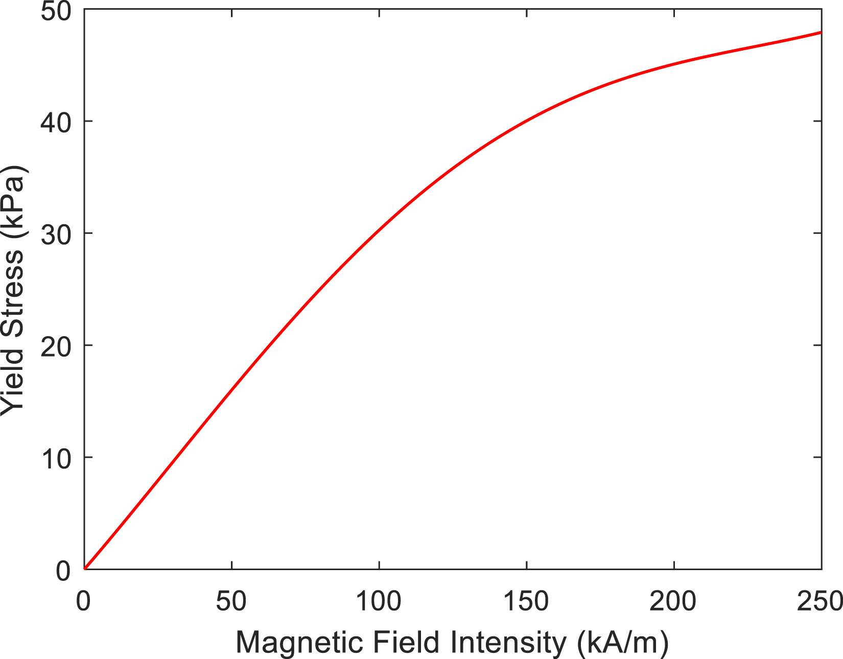
The relationship between them can be obtained by curve fitting, as shown below:
The plate model is used to analyze the mechanical behavior of MR fluid in the damping path. The coordinate setting is shown in Figure 6(a). In the figure, (a) Schematic and coordinate system of parallel plate model, (b) flow diagram of MR fluid in orifice.
The pressure drop caused by flow can be expressed as:

The relationship between volume velocity, pressure drop and shear yield strength between parallel plates can be expressed as
16
:
In the form of gradient, the above equation is expressed as follows:
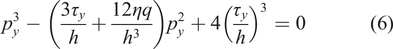
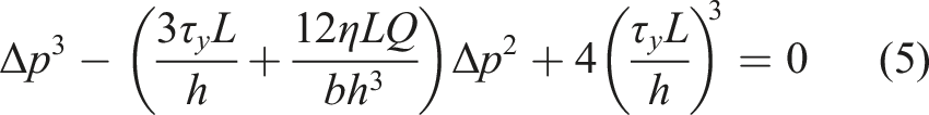
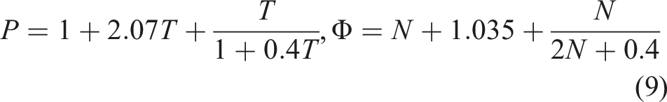
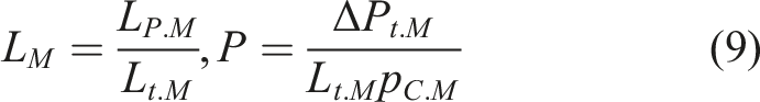
In order to simplify the equation, dimensionless analysis is used, and the following dimensionless parameters are used:
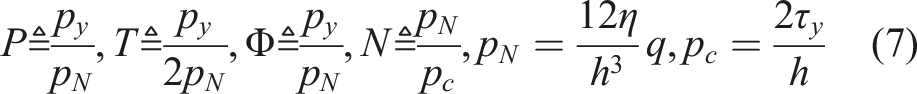
Using the above dimensionless parameters, equation (6) can be expressed as:
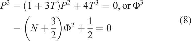
The approximate solution of equation (8) can be obtained by numerical method.
17
There are two groups of magnetic pole and magnetic shielding ring. So the MR fluid passing through the main orifice is Bingham fluid-Newton fluid-Bingham fluid, as shown in Figure 7. Flow diagram of MR fluid in main orifice.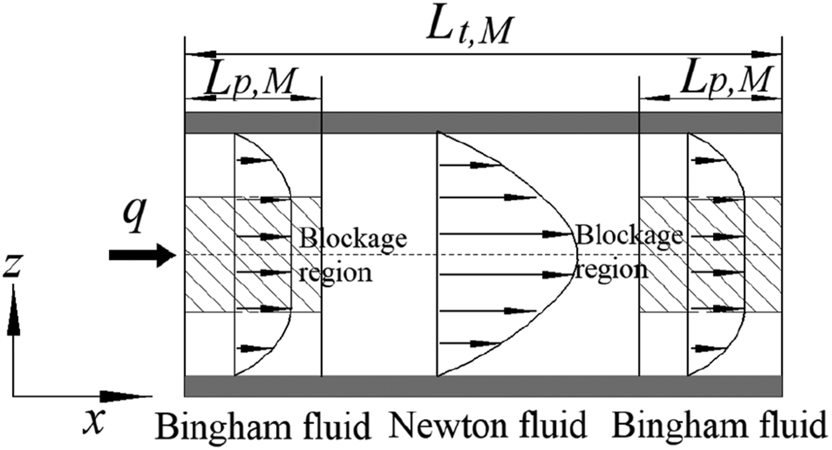
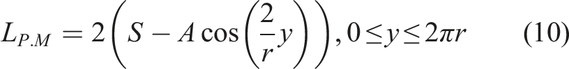
The relationship between the pressure drop and the flow velocity through the main orifice can be obtained by using the equation derived previously. For ease of analysis, the following dimensionless quantities are defined: Definition of magnetic pole function.
The pressure drop in the main orifice can be expressed as:

Divide both sides of the equation by

Considering the nontrivial solution of
The total flow through the main orifice can be obtained by integrating along the
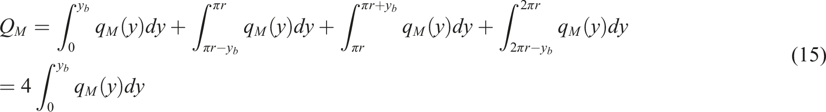
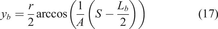
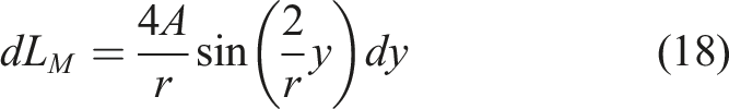
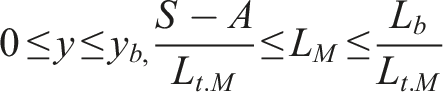
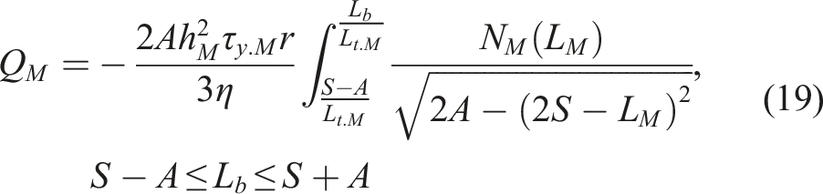
Combined with Equations (15), (17), and (18), the total flow rate of the main orifice can be obtained:
The bypass orifices are two rectangular orifices with the same size and symmetrically arranged. Coils with the same number of turns are arranged symmetrically on both sides of the rectangular orifices, to ensure that the magnetic field intensity of the two rectangular orifice is the same. There is only Bingham fluid in the rectangular orifices, and the length of the rectangular orifice is much larger than the width, so the parallel plate model is also used. When the MR fluid flows through the bypass orifice, equation (5) can be expressed as:
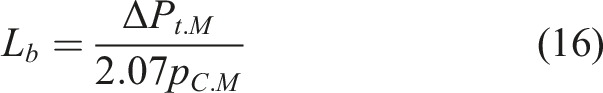
With the increase of the main coil current, the blocking phenomenon first appears at the maximum effective pole of the main orifice, and the corresponding critical pressure drop is:
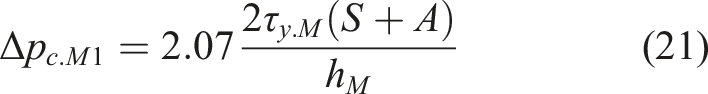
With the further increase of current, the main orifice blocking area increases. When the minimum magnetic pole is blocked, the main orifice is blocked completely, and the corresponding pressure drop is as follows:
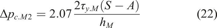
Therefore, when the pressure drop between the upper and lower interfaces of the main orifice is greater than
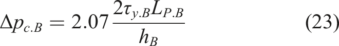
When the pressure drop of the bypass orifice is greater than
According to the continuity Equation, the relationship between the total pressure drop and the total flow can be obtained as follows:


When the damper is in quasi-static motion, and the mechanical friction is ignored, the damping force is obtained as follows:
Structural parameters of the damper.

Damping force control
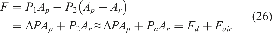
As mentioned earlier, when the piston is at low velocity, a large current is applied to the secondary coil to close the bypass hole, the main coil current is used to control the effective area of the main orifice to adjust the damping coefficient. At high velocity, the bypass orifice is open. When a magnetic field of 200 kA/m is applied to the bypass orifice, the damping characteristics of the damper are obtained by controlling the magnetic field intensity of the main orifice, as shown in Figure 9. It can be seen from the figure that the damping coefficient increases significantly with the increase of applied magnetic field intensity before the point of slope breaking. At the same time, with the magnetic field intensity of 200 kA/m, the damping force at the slope breaking point can be calculated by using the formula mentioned above, and the calculated result is 1586 N. For qualitative analysis, the damping characteristics before the slope breaking point are linearized, the approximate damping coefficients are 4214 Ns/m, 5835 Ns/m, 6995 Ns/m, 9242 Ns/m respectively when the magnetic field intensity are 0, 50, 100, 200 kA/m. Damping characteristic diagram of control main orifice.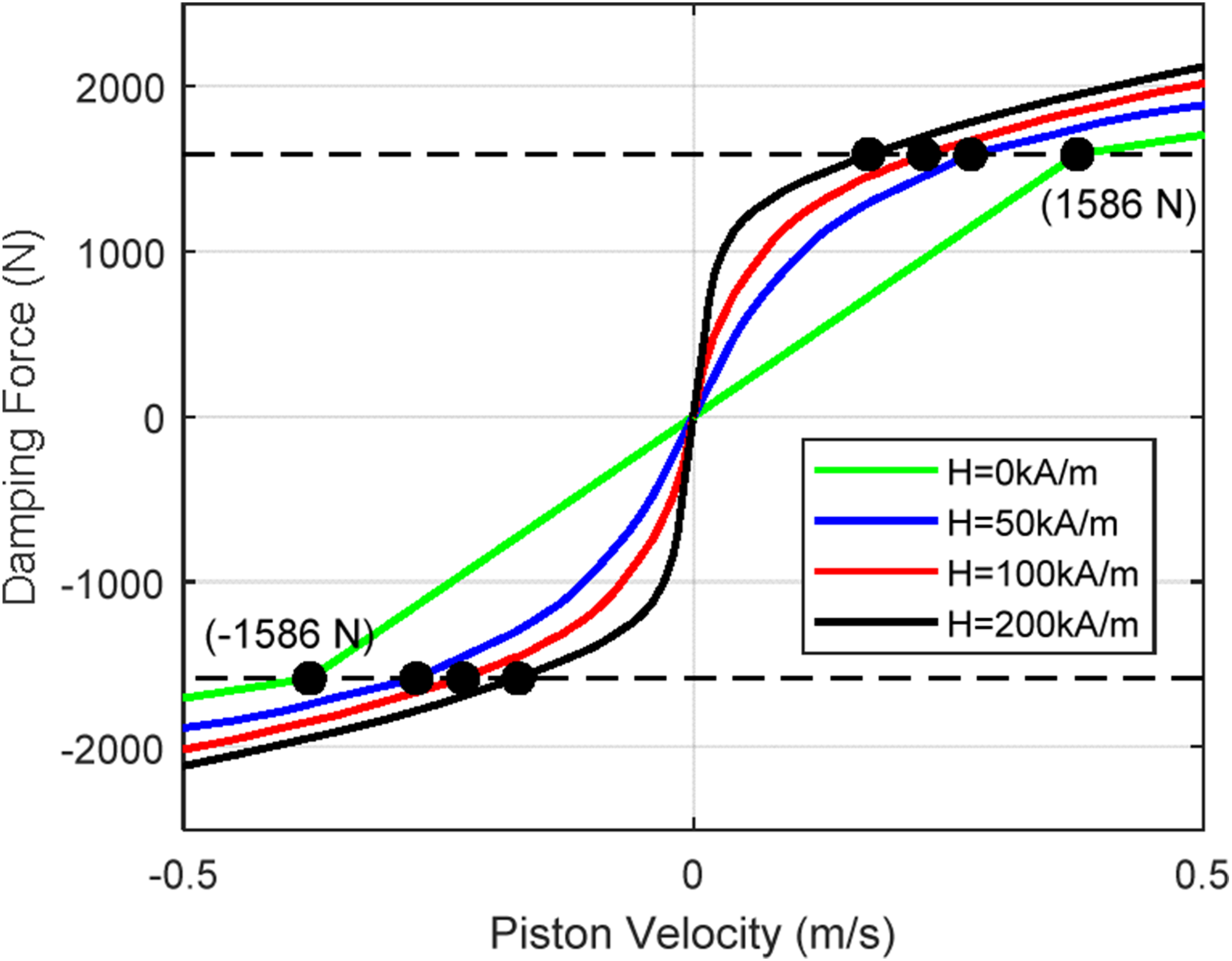
When the piston is at high velocity, the damping force of the bypass orifice has an important influence on the damping characteristics of the damper. To avoid the influence of the damping force change of the main orifice on the analysis of the damper damping characteristics. A large magnetic field of 220 kA/m is applied to the main orifice to ensure that the damping force of the main orifice is constant. The magnetic field intensity of 0, 50, 100 and 200 kA/m was applied to the bypass orifice. The simulation results are shown in Figure 10. It can be seen from the figure, the damping forces corresponding to the slope breaking point are 657 N, 938 N and 1464 N respectively under different magnetic field intensity. In the high velocity region, the damping force increases significantly with the increase of the magnetic field intensity of the bypass orifice. Damping characteristic diagram of control bypass orifice.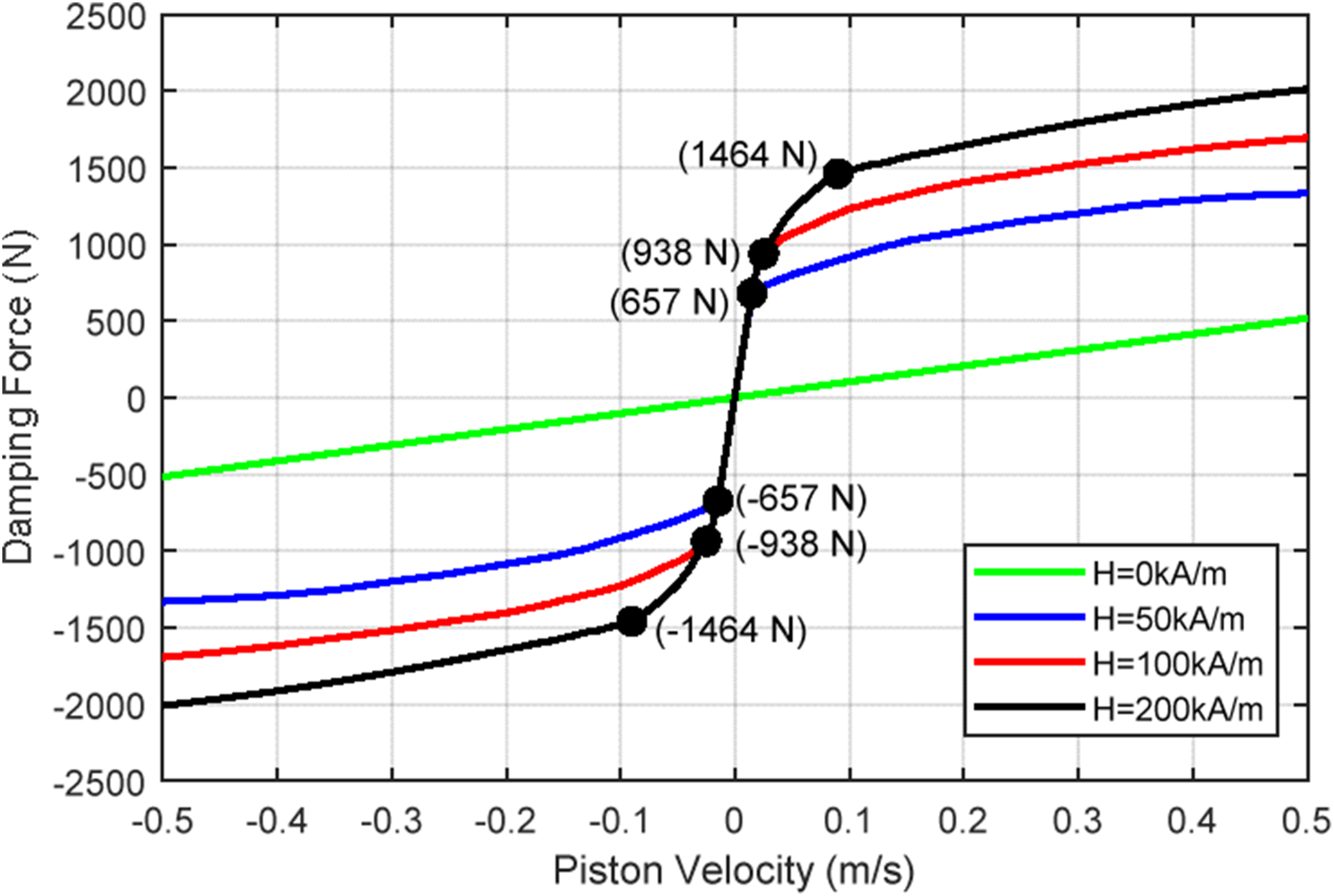
Through the control analysis of the main and bypass orifices, it is proved that the damping coefficient in the low velocity region, the damping force in the high velocity region and the position of the slope breaking point can be controlled effectively.
Ride comfort analysis
Suspension system
In order to analyze the performance of the proposed damper, a four degree of freedom half vehicle model as shown in Figure 11, is established, and the performance of the ordinary damper and the proposed MR damper in vehicle ride comfort is analyzed. The body is assumed to be rigid and has two degrees of freedom (vertical and pitch). The body is connected with two unsprung masses, which has one degree of freedom in the vertical direction respectively. Vehicle ride comfort can be analyzed by body vertical vibration and body pitch angle. Four degree-of-freedom half-vehicle model.
According to the half vehicle model, the kinematics equation of the system can be obtained:


Road roughness is the main cause of suspension vibration. Using the road spectrum function, the time domain function of road input vehicle excitation can be expressed as
18
:
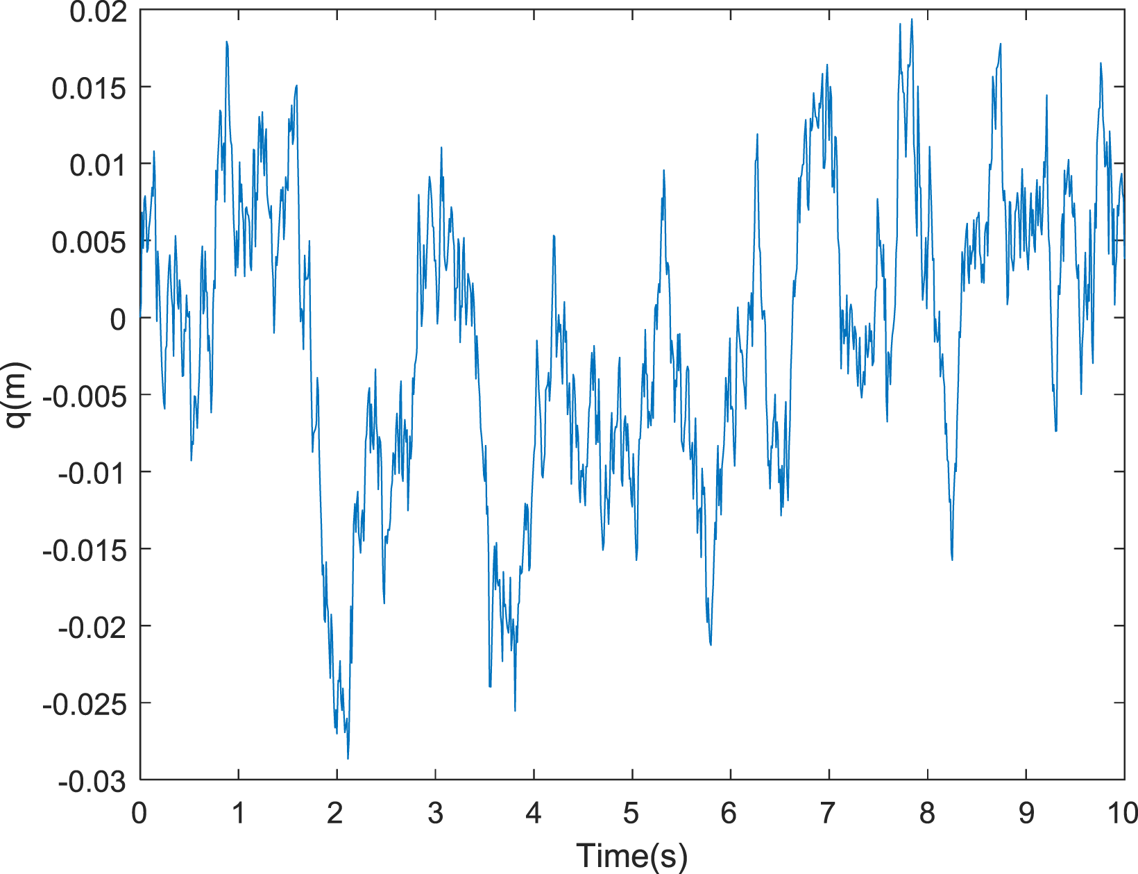
Considering the excitation time delay of front and rear wheels, the excitation relationship of front and rear wheels can be expressed as: Time domain diagram of class B road.
LQR controller design
The state vector of vehicle dynamic system is defined as:
The output vector is as follows:
The system differential equation is rewritten as space state equation as follows:
Body acceleration, pitch angular acceleration, suspension dynamic displacement, tire dynamic deflection and damping force of MR damper are selected as control objectives. The control objective is to select the minimum performance index, and it can be expressed as:
Transforming index function into matrix:
The optimal damping force is:

The feedback gain matrix
Analysis of simulation results
The parameters used in the half vehicle model.

Because the weighting coefficient has a great influence on the control result, after several trial calculations, the weighted coefficients are determined as follows:
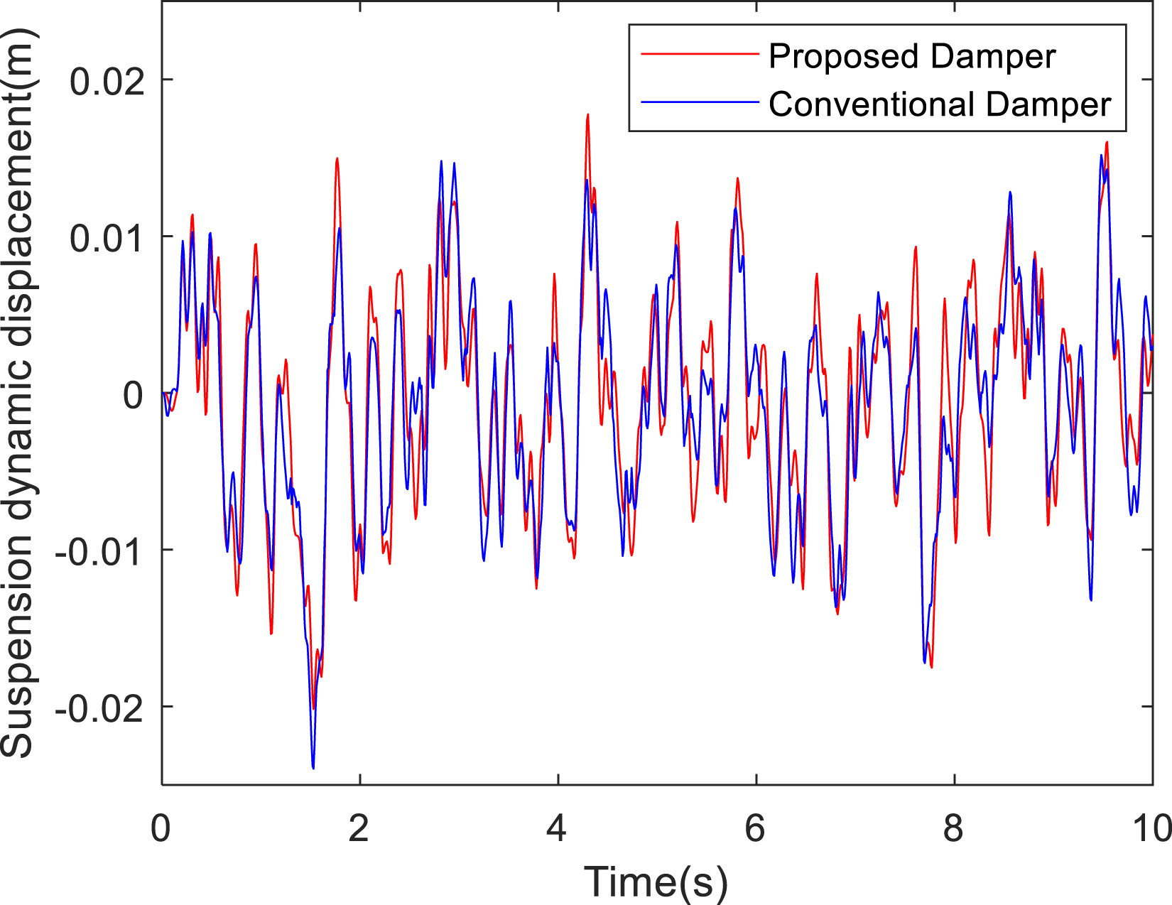
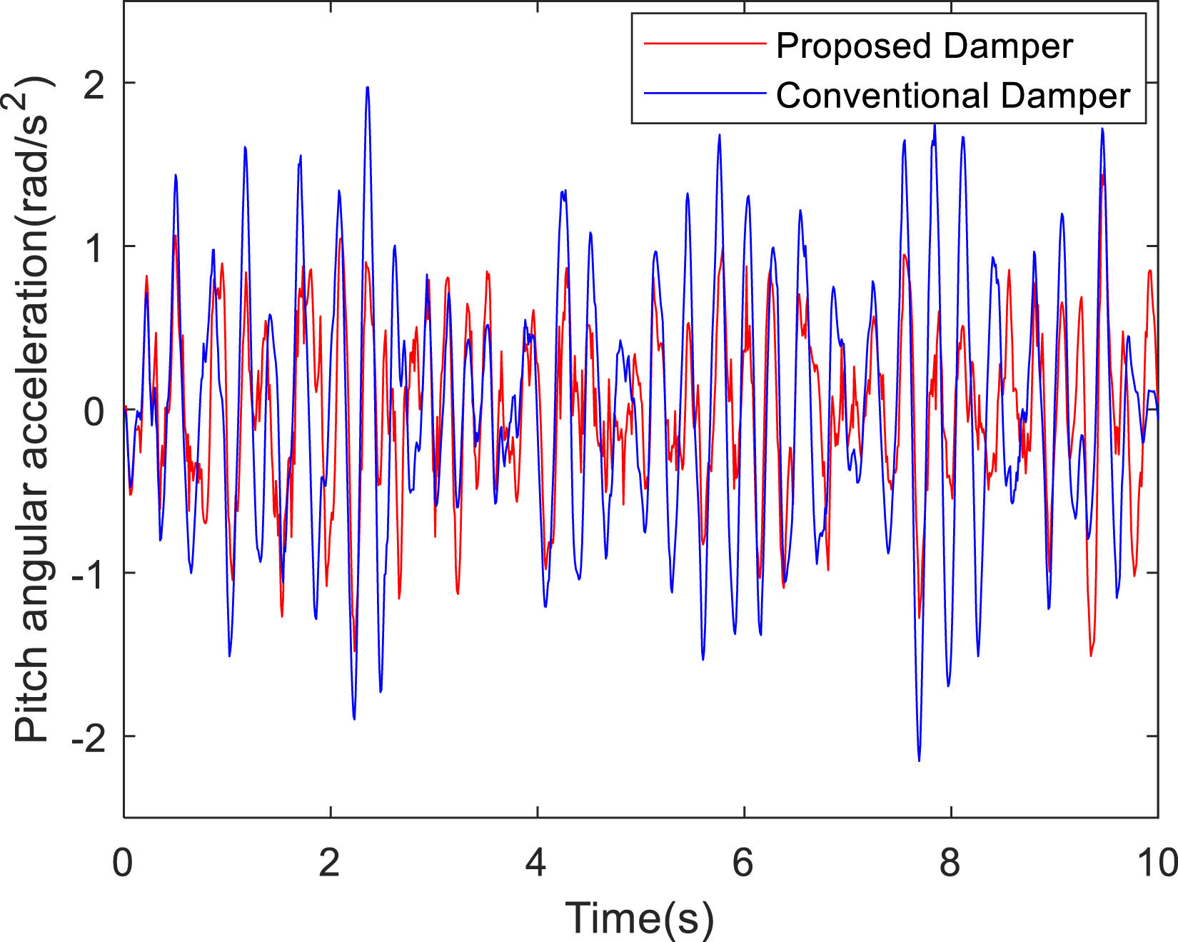
The time domain curves of vertical acceleration of mass center, pitching angular acceleration, front suspension dynamic displacement of half body through simulation. The results are shown in Figures 13–15. Comparison of acceleration of center of mass. Comparison of suspension dynamic displacement. Comparison of pitch angular acceleration.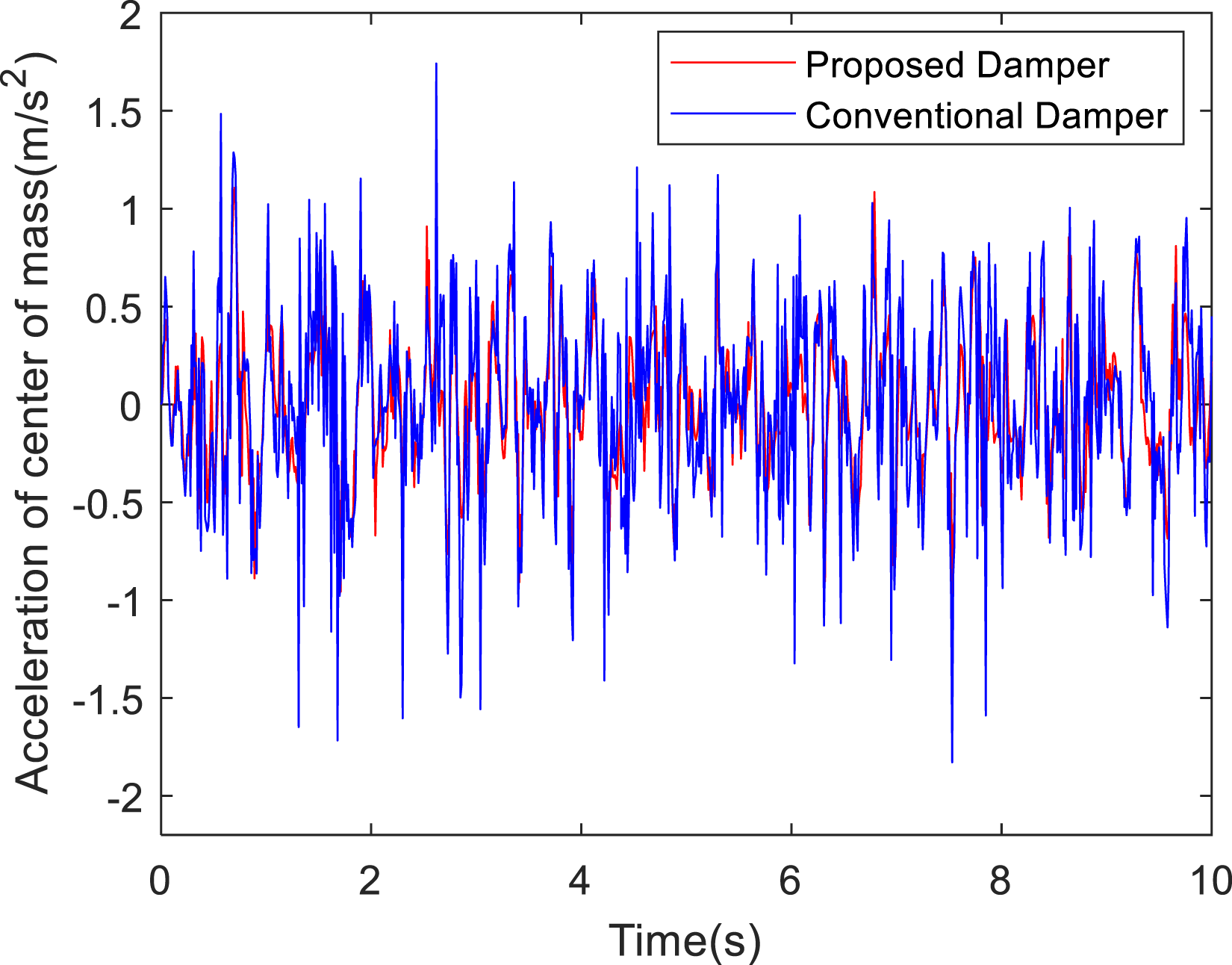
Root mean square value of suspension dynamic performance index.

It can be seen from Table 3 that, after using the proposed damper, the body acceleration and pitch angular acceleration are reduced by 31.13% and 32.8% respectively. This shows that the ride comfort of the car has been significantly improved. However the dynamic displacement of suspension increased by 13.21%, but it does not exceed the limit dynamic displacement, the elastic stop will not impact the body, that is to say, the handling stability of the car is slightly reduced, but it has little effect. It shows that there is a certain contradiction between improving vehicle ride comfort and handling stability.
Conclusion
A improved MR damper is proposed, and the magnetic pole of the damper is designed to be sinusoidal, so that the effective flow area of MRF can be adjusted by controlling the effective length of magnetic pole. Because the magnetic pole is symmetrical about the axis, the equivalent torque formed by the force acting on the piston surface can be balanced. The mechanical model of the novel damper is established based on Bingham fluid. By controlling the magnetic field intensity of the main channel, the effective flow area can be controlled. With the opening and closing of the bypass hole, the damping coefficient of the damper in the low velocity region of the piston, and the damping force in the high velocity region can be effectively controlled, which can meet the requirements of the automobile on the damping force under various driving conditions. Then, a four degree of freedom vehicle body model is established, and LQR controller is designed. The influence of the proposed damper and ordinary damper on vehicle ride comfort is analyzed by simulation. The simulation results show that the proposed damper can effectively improve the performance of ride comfort. The follow-up work is to process the proposed damper, and verify the excellent performance of the proposed damper through experiments.
Footnotes
Declaration of conflicting interests
The authors declared no potential conflicts of interest with respect to the research, authorship, and/or publication of this article.
Funding
The authors disclosed receipt of the following financial support for the research, authorship, and/or publication of this article: This work was supported by the Natural Science Foundation of Henan Province Project (242300420044), the Key Scientific Research projects of colleges and Universities in Henan Province (23A460022, 25A46023), the Key scientific and technological projects in Henan Province (242102221012, 242102231017, 242102210008, 251100220200), Training plan for young backbone teachers in Colleges and Universities of Henan Province (2025GGJS148), Excellent case engineering project “Noise and Vibration Control Engineering” (YJS2025AL141).