
Abstract
The stability of automatic firearms during discharge is a crucial element that influences precision and safety. Current research often overlooks the synergistic influences of the shooter and the firing environment on weapon dynamics. This research seeks to create a dynamic model for a gas-operated pistol affixed to a bipod, considering the interplay of the shooter, the ground, and the weapon system. The dynamic model is constructed using the Lagrange theorem and the principles of multi-body system dynamics. An elastic and viscous damping connection is implemented to model the interaction between the shooter, ground, and weapon. The bipod-mounted UK-59 machine gun serves as a case study for dynamic simulations. The simulation findings precisely replicate the actual motion of the handgun and validate adherence to the manufacturer’s design specifications. The investigation underscores the influence of structural characteristics on firing stability. The suggested modeling methodology offers a dependable foundation for the evaluation, calculation, and design enhancement of automated weapon systems. The findings are significant for instructional applications and for enhancing weapon design and firing stability.
Introduction
Improving national defense capabilities and modernizing arsenals are critical priorities for many national armed forces. This investigation is critically significant to several military forces worldwide as it seeks to ensure the autonomous operation of the supply chain. To attain proficiency in weapon design and manufacture, it is essential to conduct a comprehensive analysis of the phenomena that transpire during fire. Computational models must precisely represent real-world scenarios to inform the design process and reduce the need for costly testing.
The fire stability of an automatic weapon is an essential characteristic that has significance irrespective of its firing capacity. Enhanced shooting stability directly corresponds with a higher probability of effectively eliminating the target. A thorough understanding of the attributes of automatic weapons and their influence on stability is crucial for the efficient operation, design, and manufacturing of these weapons. Documents and studies that provide a thorough analysis of the operation and attributes of weapon systems mounted on wheeled and tracked platforms, as well as bipods or tripods, are still constrained by several limitations and are seldom reliable. A significant corpus of literature exists that investigates this topic, including papers numbered 1 to 19. Numerous studies have either neglected or only partly examined the influence of the shooter on the weapon system, seeing it either as a passive elastic component or a fixed load. Balla et al. 1 investigated the dynamic response of the automatic weapons on the tripod during working performance. The presented dynamical modeling has eight degrees of freedom. The computed outcomes were evaluated on the real weapon system. Balla 2 performed a vibration study on the key components of the armament system, specifically focusing on the areas where the automated cannons are installed. The dynamic model consists of 8 degrees of freedom (DOF) and is divided into three components: the hull, turret, and elevation portions. Krist and coworkers 3 presented novel methodologies for studying vibrations in automatic weapons installed in battle vehicles. The BMP-2 IFV example explains the techniques for preparing experiments, the relevant experience, and examples of how to evaluate the measured findings under direct firing from a tracked combat vehicle. Sun and colleagues 4 provided an assessment of the dynamic characteristics exhibited by a four-wheeled vehicle equipped with a machine gun. Three components compose the total system: the firearm, the flexible monopod, and the vehicles. The multi-rigid bodies of the weapon consist of a rigid receiver, bolt, projectile, buffer, and recoil spring. Le Cong and his research team 5 addressed the characterization of the vibration of military vehicles during simultaneous bursts of fire and motion on the field of battle. The models with three degrees of freedom are given. Thai et al. 6 presented an evaluation of shooter-weapon system vibration when firing from a biomechanical point of view. The biomechanical framework of shooter arms was designed by considering the forces of the muscles and tendons. Mihaylov 7 presented a basic model of small-arms firing. The Monte Carlo approach was used to consider the diverse parameters influencing the impact point and the varied sizes and forms of the targets. The model’s parameters allowed the investigation of firing efficacy across diverse weapon types and target categories. The efficacy of the AK-47’s fire against a specific target has been examined over various distances and shooting positions. Nguyen and collaborators 8 investigated the possibilities of lowering the vibration caused by the tuned mass dampers (TMD) that absorb vibrations for weapons when they are placed on the vehicle. The calculation examples are for anti-aircraft machine guns with a 12.7 mm NSV caliber that is mounted on vehicles with the UAZ-469 designation. Lu and his team 9 examined the feasibility of minimizing the oscillation of the tuned mass dampers (TMD) used for weapons when they are installed on vehicles. The above estimates pertain to the versions of 12.7 mm NSV anti-aircraft machine guns that are installed on UAZ-469 vehicles. Stewart 10 articulated a streamlined methodology for measuring a reliability-based design load factor (RBDF) about the unpredictability of explosive blast loading. The user may pick variability in range and explosive mass, as well as model errors, to produce RBDFs for pressure and impulse. Hui et al. 11 developed a coupling model for the fuse, projectile, and barrel, and performed an implicit-explicit sequential finite element dynamic simulation to precisely examine the reaction of ammunition components to shock loads during the whole launch process. Readers can refer to some related works published recently.4,12,13
Assessing the precision of the given theory and model is crucial for conducting experimental investigations on weapon dynamics. This serves as a crucial base for the calculation, design, and enhancement of weaponry. Van Hung et al. 14 focused on developing a mathematical model to accurately represent the rotating movements of a projectile and the force that propels it. This research investigated the influence of a rifling twist on the propulsive force and rotational motion of the rotation band about four different rifling variants used in the 23 mm ZU-23-2 anti-aircraft gun. Balla and collaborators 15 analyzed the motion of the breech block carrier and the firearm casing of an automated firearm mounted on a movable platform and the weaponry’s base. Phan Hoang and coworkers 16 performed experimental and numerical investigations to evaluate the efficacy of high-strength metals in shielding against API BZ projectiles. Anjaneyulu and Sai 17 delivered a presentation on the design as well as an evaluation of tripods. Through the application of the dynamic theory of multi-rigid body systems, Van Hung and colleagues 18 developed a dynamic model of the gas-operated machine gun’s ammunition belt. Additionally, an empirical investigation was conducted on the PKMS Kalashnikov 7.62 mm machine gun to validate the model’s dependability. Some other recent studies can be explored further.19–21
This study establishes a complete dynamic model that combines the interactions between the shooter and the supporting ground, unlike earlier research that normally analyzes automatic weapon dynamics without this consideration. The model depicts the shooter–ground–weapon system using elastic and viscous damping connections in three translational axes (x, y, z). Furthermore, the suggested formulation employs multibody system dynamics and the Lagrange equations to encapsulate the interrelated motion of the weapon, bipod, and shooter, including seven degrees of freedom. This method allows a more accurate assessment of firing stability under burst circumstances, essential for design validation and performance enhancement.
The primary aims of this research are as follows: - To create a multibody dynamic model of a bipod-mounted, gas-operated machine gun that incorporates the shooter and the ground as essential elements of the system. - To formulate the governing equations of motion using the Lagrangian formalism and to solve them numerically under diverse firing circumstances. - To assess the dynamic reactions, including recoil displacement, angular rebound, and velocity profiles, of the weapon system in both vertical and horizontal orientations. - To ascertain essential factors (mass moments of inertia, stiffness, damping coefficients) that significantly affect firing stability.
Materials and methods
The study examines the motion of gas-operated firearms when they are fired using a bipod. The dynamical modeling of the shooter-weapon system is constructed by using Lagrange equations and including the biomechanical modeling of the shooter’s arm and shoulder. The UK-59 machine gun with a bipod attached was selected for this experiment (Figure 1). UK-59 machine gun on the bipod.
The measurement of the impacts of terrain and the soldier is approached differently from prior studies by using elastic-damping coupling along the x, y, and z axes. The model facilitates a comprehensive investigation and comprehension of the gun’s stability. The aforementioned dynamic model may be used for the automatic weapon systems that are placed on the bipod. The collected data will serve as the basis for the next investigation, which examines how the structural features impact the overall stability of the operation. Furthermore, this acts as the basis for enhancing the overall configuration of the weapon system.
Formulation describing the oscillation of the UK-59 machine gun on the bipod
Assumptions
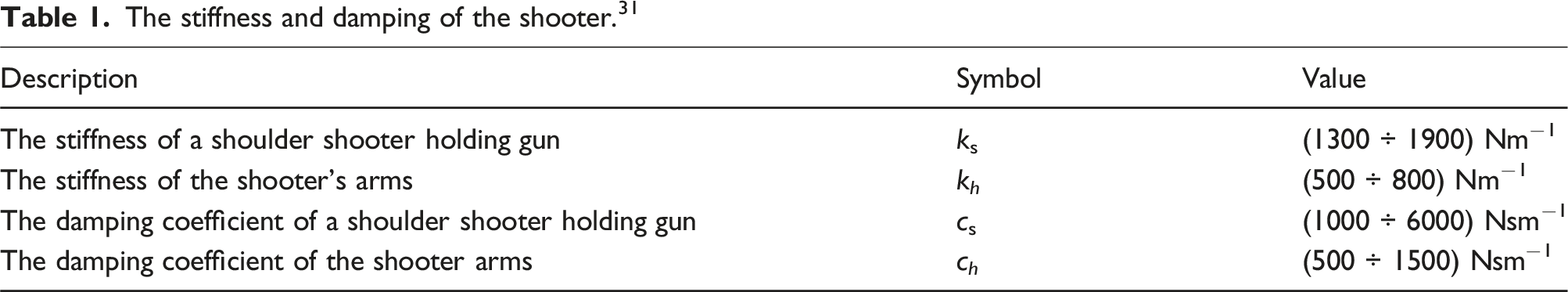
To formulate the dynamic model of the bipod-mounted gas-operated machine gun, the following assumptions are posited22–24: - Rigid bodies: The primary elements of the weapon system (barrel, receiver, and bipod legs) are represented as rigid bodies with concentrated mass and inertia. - Linear connections: The interconnections between components are presumed to be perfect hinges or stiff linkages devoid of clearance or backlash. - Shooter representation: The shooter is shown as a concentrated mass linked to the weapon system and the ground via linear elastic and viscous dampening components. Shooter fatigue and variations in posture while shooting are not taken into account. The shooter’s loads exerted on the mechanical framework are represented as a viscous system in three directions of translation, each with its associated parameters k and c. By making this presumption, we may substitute the influence of the shooter’s shoulder with a spring that has a stiffness of k
sj
and dampening with a viscous coefficient of resistance c
sj
in the correct direction. The shooter’s hands exert a force on a spring with stiffness of k
hj
and a damping impact with viscous coefficients of resistance chj (j = x, y, z) in the corresponding direction. The part of the shooting moving mass while firing is replaced by the mass centralization, located at the shooter’s shoulder. - Ground model: The topography is represented by an elastoplastic model comprising dampers with a viscous parameter of c
gj
(j = x, y, z) and a linear spring with stiffness k
gj
. - Gas operation: The internal gas-operated mechanism is streamlined as a defined impulsive force exerted on the moving components, with time determined by manufacturer specifications. - External effects: Aerodynamic drag, wind disturbances, and temperature influences are disregarded. Temperature according to Vietnam conditions: ambient temperature 25°, humidity 70%, atmospheric pressure.
25
- Small rotation assumption: Angular displacements are assumed to be sufficiently small to permit the linearization of kinematic relationships.
These assumptions provide a manageable dynamic formulation with the Lagrange method while preserving the primary physical factors that impact firing stability.
Figure 2 presents a dynamic model of the UK-59 machine gun, which is placed on a bipod. This model is based on the current structure and the connections between the different sections of the weapon system. The model of the weapon system mounted on the bipod.
The model of the weapon system includes three rigid bodies: - Body 1: Shooting shoulder with mass - Body 2: The bodies of the weapon casing, barrel, and bipod with mass - Body 3: Fundamental mechanism (bolt carrier) with mass
One must examine the body k of the weapon’s moving components, which are influenced by the motion of the basic mechanism (body 3). Two principal functioning mechanisms of the UK-59 machine gun, namely the feed mechanism (k 1 ) and the bolt (k 2 ), significantly affect the movement of the fundamental mechanism. SolidWorks software determines coefficients such as body mass, moment of inertia, and center of mass coordinates.
To examine the movement patterns of the system, the Cartesian coordinate system has been implemented at the center of mass of each component and the whole system, as seen in Figure 2. The purpose of this is to facilitate the analysis of the system’s dynamics.
+
+
From the assumptions and kinetic constraints between objects, the system has seven independently generalized coordinates.
The generalized coordinates [q k ] = [q k1 , q k2 ] represent the angular displacement of the feeding mechanism (k 1 ) and the bolt (k 2 ), which are influenced by the movement of the fundamental mechanism (body 3). The variables q k1 and q k2 represent the angular displacements of body k 1 about the X k1 -axis and body k 2 about the X k2 -axis, respectively.
The shooter-weapon system under examination consists of nine generalized coordinates, with q 1 to q 7 representing the independent generalized coordinates. q k1 and q k2 are generalized coordinates that are dependent on each other.
The kinetic energy description of the system
The kinetic energy equation of the structure is generally given by:
The kinetic energy of the i-th body of the structure is written by26–29:
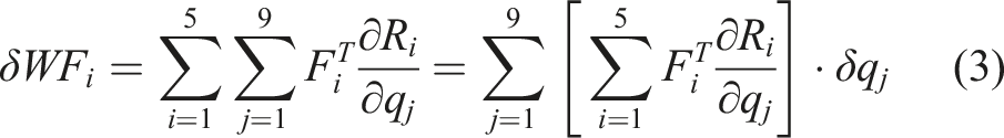
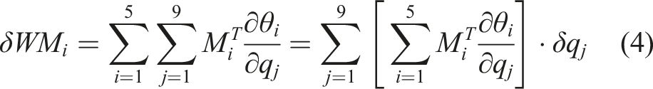
Virtual work of generalized load
The virtual work and generalized load are computed as26–29:
Let us consider the virtual work of generalized load F
i
as:
Analysis of forces and moments acting on the mechanical system when firing
The principal force components acting on the fundamental mechanism (body 3)
Figures 3 and 4 depict the main forces that are acting on the basic mechanism, which is represented by body 3. Figures 3 and 4 illustrate the forces acting on the basic processes in recoil and counter-recoil, respectively. The forces exhibit cyclical behavior when series firing is used. The publications30–32 include a precise definition and an extensive analysis of these factors. The force components affecting the bolt carrier during recoil. The force components affecting the bolt carrier during counter-recoil.
Symbols in Figures 3 and 4: (1) – Bolt carrier; (2) – Return spring; (3) – Shock absorber spring; (4) – Guide rail on the weapon casing; (5) – k-th working mechanism.
Forces and reactions: F
pk
: The driving reaction force acts on the piston. P
k
: Generalized force acting on the k-th working mechanism. P
3
: Gravitational force of body 3. X: Displacement of the bolt carrier. X
k
: Displacement of the k-th working mechanism. F
rs
: Reaction force of the return spring. F
bu
: Reaction force of the shock absorber. F
cf
: Impact force between the bolt carrier and the receiver. F
rd
: Reaction force for removing a cartridge from the belt. R
v
: Reaction force for extracting a cartridge from the chamber. P
b
: Resistance force of the magazine. F
f
: Friction force between the bolt carrier and the guiding groove on the receiver.
The main forces affecting the receiver during the firing operation
The pressures exerted on the receiver’s interior throughout a firing depend on the specific kind of automatic weapon.30,32 Figure 5 depicts the stresses exerted on the receiver in a gas-operated weapon system. The forces exhibit cyclic behavior when series firing is used. The publications
25
and
27
provide a comprehensive description and thorough study of these factors. Figure 6 illustrates the stress exerted on the mount during the discharge of three-round bursts. The force components affecting the weapon casing. The force components affecting the mount.
The symbols in Figure 5 represent the following forces: F H - force of the shot; F pl - force on the gas chamber; F bu - force of the shock absorber; F rs - force of the return spring. F rcf refers to the force exerted when the bolt carrier strikes the rear of the weapon casing during recoil. Ffcf, on the other hand, represents the force exerted when the bolt carrier strikes the front of the weapon casing during counter-recoil. F arf refers to the auxiliary resistance force exerted by the automatic firing system on the weapon casing. This includes forces like cartridge case extraction force (R v ) and the friction force between the bolt carrier and the guide rail on the weapon casing (F f ). P 2 represents the gravitational force acting on body 2, while M x2 represents the resistance caused by the rifling torque on the weapon casing.
The effect of the shooter on the gun
The outcome of the shooter’s action on the gun is contingent upon the shooter’s health and the force of their strike. The shooter’s force operating on the gun while shooting may be determined by analyzing the body movement. This force consists of the shoulder-supported firing force and the arm-holding shooter force, as shown in Figure 7.
31
The force applied by the gunner on the gun.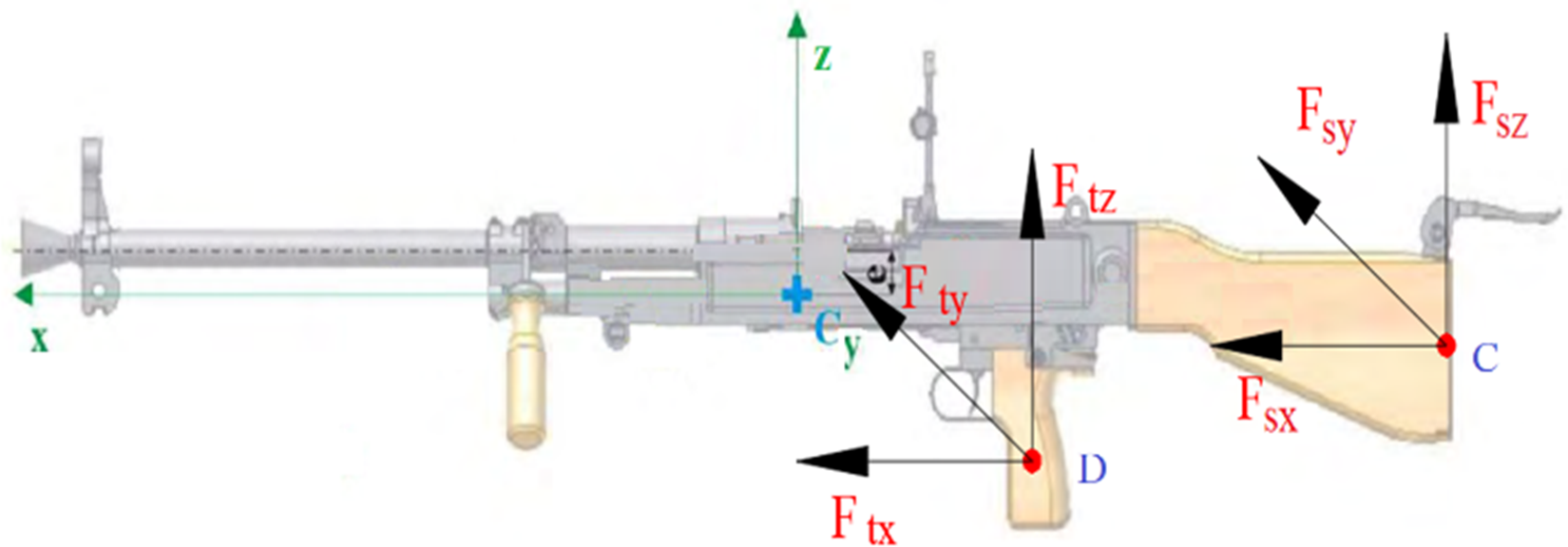
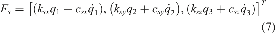
The force components affecting the gun are calculated as follows:


The force components between the terrain and the bipod supports at spades A and B
In this study, the effect of the background mounted on the bipod is characterized by elastic-damping linkages along the z-axis.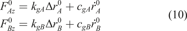
The friction force F
ms
along axis x, y is determined as the following formulas: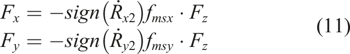
The gravity of bodies
The gravitational force exerted by the body’s P
ig
on the i-th body is directed towards the center of the body. It is perpendicular to the horizontal plane O0X0Y0 and has a magnitude on the ground. The gravity of the i-th body is expressed in the fixed coordinate system:
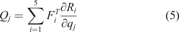
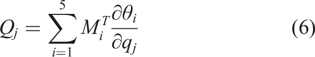
Fundamental differential system
After calculating total kinetic energy T, generalized force Q
j
, put on the results in Lagrange equation (13), one obtains the system of nine differential equations of the 2nd order,.34,35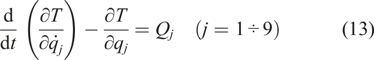
in which T – the system kinetic energy; q j – generalized coordinate j-th; Q j –force corresponding to the coordinate q j .
By using the dynamic link between k body and body 3 through gear ratio k
k
and efficiency η
k
according to 26,27,35, we have the following relationship: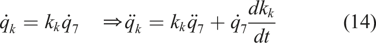
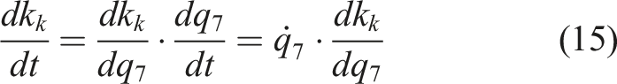
Substituting equation (15) into equation (14) gives: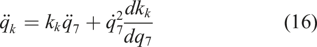
On the other hand, we have: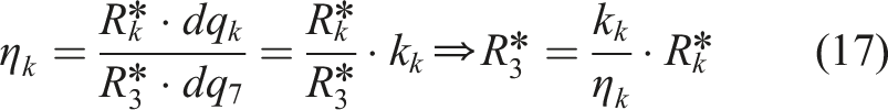
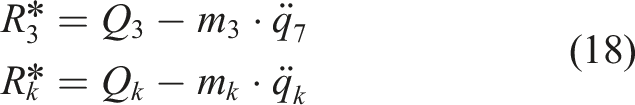
By substituting formulas (14), (15), (16), (17), and (18) into the system of differential equation (13) and after the arrangement, one gets a system of nine differential equations of the second order (19):
Results and discussions
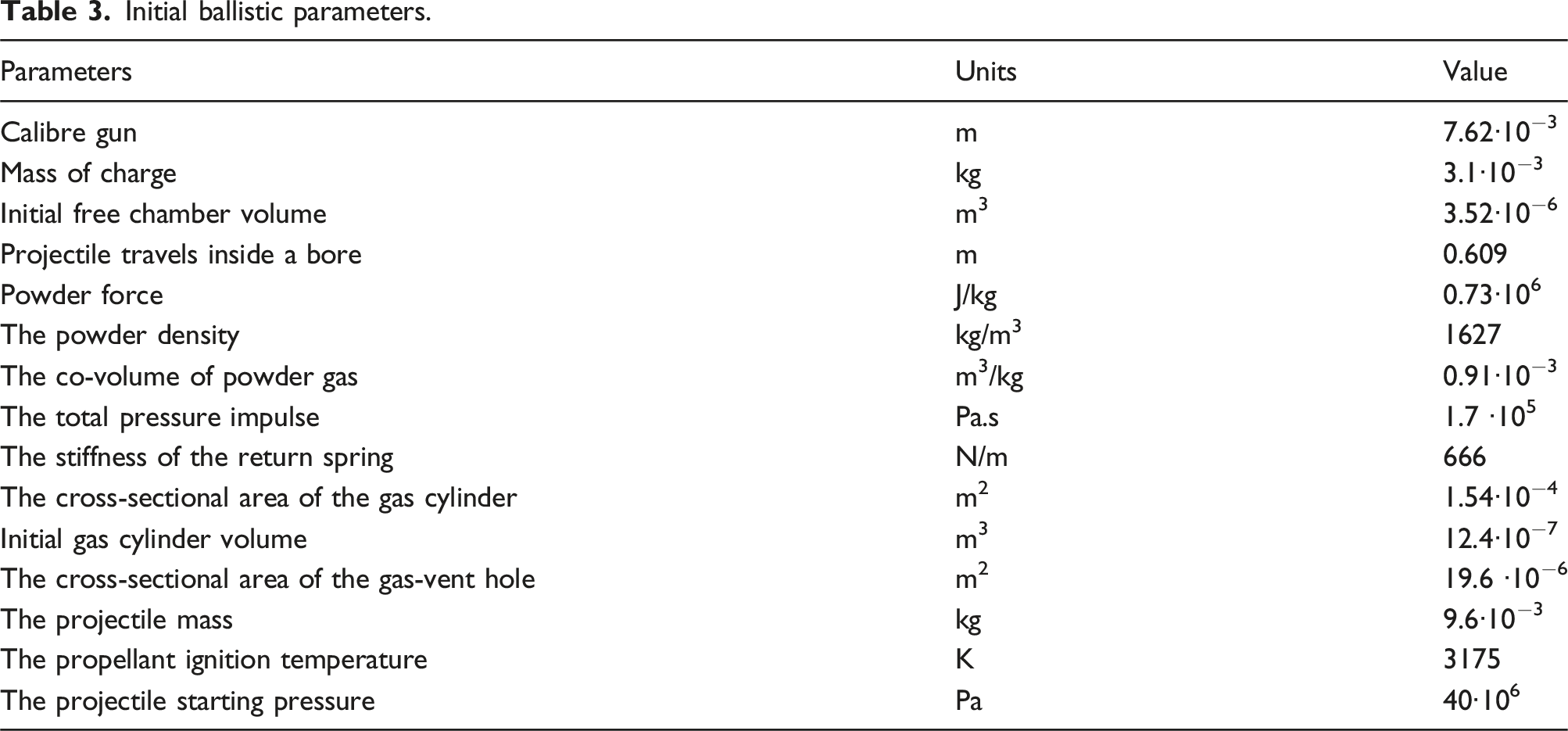
To resolve (19), it is essential to ascertain the input parameters, which include internal ballistics, the interaction between the soldier and the weapon, and the terrain, among others. The characteristics of ballistics, mass, and dimensions are specified in technical documentation. Furthermore, the SolidWorks program is used to ascertain the parameters of the moment of inertia and the center of gravity of the analyzed item.
Mass and moment of inertia of the structure.

Initial ballistic parameters.
The system of equation (19) is resolved via the numerical integration method. Equation (19) is calculated in conjunction with the internal ballistic issue to provide an exact solution, while Matlab software is used to investigate the thermodynamics of the chamber. 27 This method is widely acknowledged as the conventional and dependable methodology for calculating the root of first-order ordinary differential equations in numerical integration issues.
Following a workout, the following outcomes are often observed: the pressure rules when the gas is present in both the barrel and the gas chamber, as shown in Figure 8; the projectile’s velocity over the length of the barrel, as shown in Figure 9; and the displacement of the bolt carrier, as illustrated in Figure 10. The table displays a selection of common outcomes, as seen in Table 4. Air pressure in the gas chamber and barrel. The velocity of the projectile. Displacement of bolt carrier (body 3). Some typical results obtained.
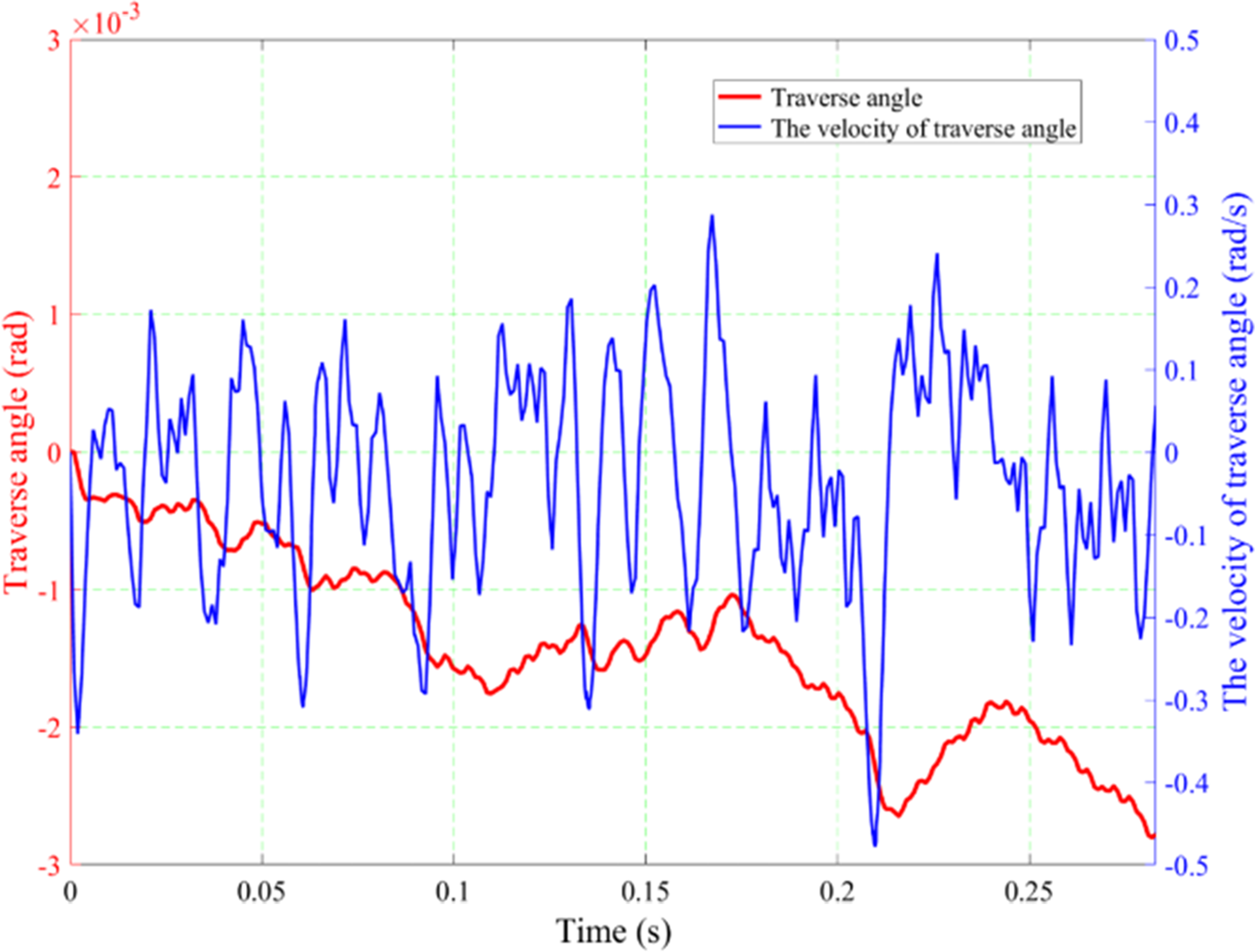
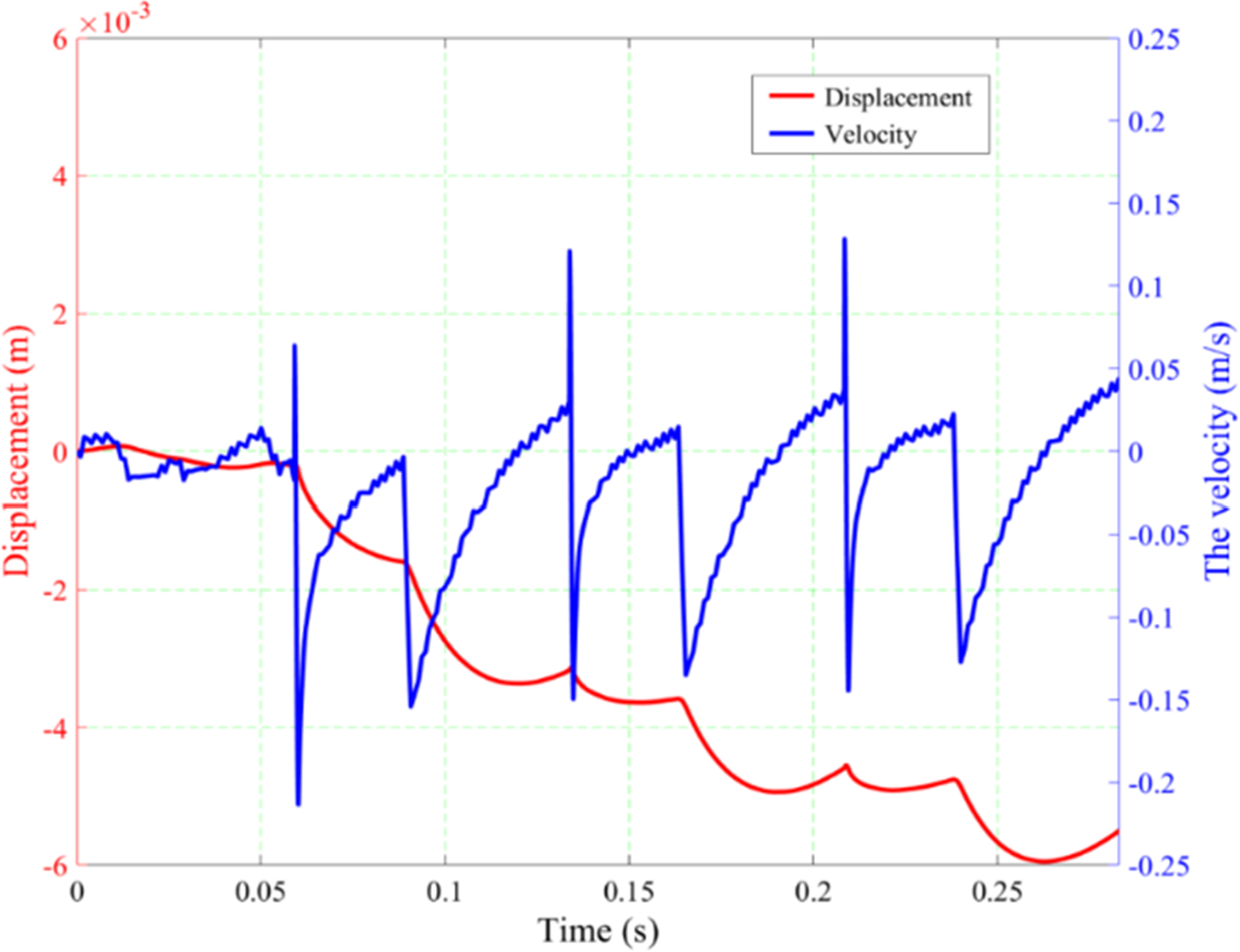
Dynamic properties, such as the weapon’s rearward movement and its angular rebound reactions in vertical and horizontal planes, serve as key indications for evaluating the firing stability of the weapon system.
27
The fluctuations in the weapon’s angular velocity and elevation angle inside the vertical plane (Figure 11) elucidate the muzzle ascent and recovery dynamics after each discharge. The angular velocity and traverse angle in the horizontal plane (Figure 12) indicate the degree of lateral deviation and possible dispersion resulting from the firing impulse. The linear displacement and translational velocity of the weapon as it traverses the bipod in relation to the terrain (Figure 13) define the overall motion and energy transfer to the supporting structure. To ensure thoroughness, these dynamic characteristics were consistently monitored and documented during three consecutive rounds fired in regulated bursts, guaranteeing that the findings reflect both transient and steady-state responses of the system. The response in the vertical plane of the barrel bounce angle. The response in the horizontal plane of the barrel bounce angle. Backward movement of the gun.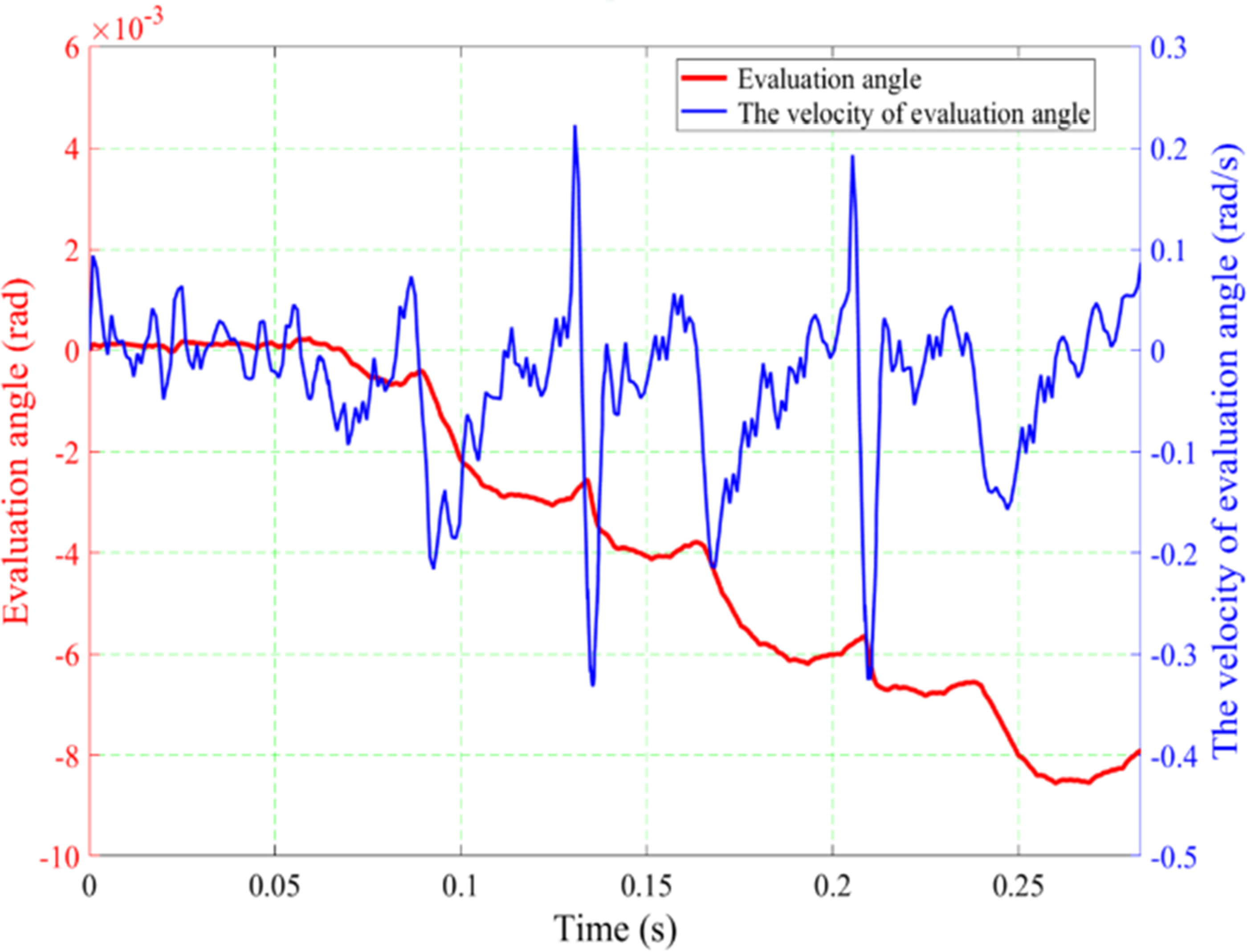
The obtained results can be interpreted as follows: - Rules of the variation of gas pressure inside a bore and the chamber are consistent with the results indicated in the documents of design and instruction.
32
The maximum value of interior pressure is 298.479 MPa, Figure 8, while the given result in the instruction according to the producer is 299.72 MPa. In comparison, the error in this circumstance is 0.41%. - The duration of a complete cycle is 0,0788 [s], and the equivalent in the theoretical rate of fire is 761 [rds/min]. The rate of fire indicated in the manufacturer’s documentation is 700÷800 [rds/min]. Thus, the calculation results are completely consistent and reliable.
This avenue of inquiry continues to face specific restrictions. This study is limited to a theoretical framework, focusing only on the dynamic analysis of the motion and velocity of bipod-mounted weapons discharged in short bursts. The precision and dependability of the findings are heavily contingent upon the accurate identification of numerous essential input parameters, including the inertial moments of the weapon components, stiffness coefficients, and damping characteristics of both the shooter and the supporting terrain. Notwithstanding these limitations, we consider our work a significant advancement and a novel contribution to resolving the issue of shooting stability in gas-operated automatic weapons fitted with bipods for short-range dispersion. Future study will focus on experimental validation, integrating empirical observations to develop the model and improve its applicability in actual operating settings.
Conclusion
This research introduced and examined a dynamic measure that offers clear criteria for assessing the shooting stability of gas-operated automatic guns positioned on a bipod during short-range burst firing. A thorough dynamic model was created using the principles of multibody mechanical systems and the Lagrange equations. The current model distinctly accounts for the interaction among the shooter, the ground, and the weapon via elastic-viscous linkages across the x, y, and z axes, in contrast to prior research. The constructed model of the UK-59 machine gun consists of five rigid bodies and demonstrates seven degrees of freedom, enabling a precise depiction of the weapon’s kinematic and dynamic characteristics. The model’s performance depends on the empirical determination of critical input parameters, including moments of inertia and viscous damping coefficients for both the shooter and the terrain. The suggested formulation improves comprehension of weapon stability across various loading scenarios, boundary conditions, and displacement modes, offering a solid scientific foundation for the design and improvement of automatic weapon systems.
Footnotes
Declaration of conflicting interests
The authors declared no potential conflicts of interest with respect to the research, authorship, and/or publication of this article.
Funding
The authors received no financial support for the research, authorship, and/or publication of this article.