



Abstract
In this research, we give an analytical demonstration of the possibility to realize a simple phononic demultiplexer based on Fano and AIT resonances for application of wave routing. Our proposed demultiplexer contains a
Introduction
Wave routing application has always been a great challenge for many physical applications. Numerous works focus on the design of multi-channel devices capable to guide waves from a specific input line to different output lines. Such devices include power divider or combiner (which divides or combines one or several inputs into one or several channels) or multiplexer systems which select one of several inputs and transfers it into a specific channel. For example, in microwave engineering, guiding devices such as power dividers, circulators, filters, couplers and multiplexer are commonly used. 1 Multi-channel devices can be realized in different ways employing resonant structures,1–3 photonic crystals,4–6 metamaterials7,8 as well as waveguides with multimode interferences.9,10 In electromagnetics, selected filters and multiplexers have also been implemented by using structured materials as nonuniform waveguide structure11,12 and complex photonic circuits are studied and designed for optical signal processing or computing in integrated optics. 13
Fano and EIT (Electromagnetically Induced Transparency) type resonances14–16 have an atomic origin, but they have been the subject of several studies in classical systems such as coupled micro-resonators,17–19 photonic waveguides,20–24 acoustic slender tube waveguides and solid-liquid multilayers25–34 as well as plasmonic nonostructures.35–39 Fano resonance can be explained as the product of two processes of constructive and destructive wave interferences. This phenomenon gives rise to a resonance followed by an antiresonance over a narrow frequency range and can be manifested by an asymmetrical profile shape. In the transmission spectra, the Fano profile appears as a maximum near to a transmission zero.40,41 When the Fano resonance falls between two antiresonances (two transmission zeros) it becomes an EIT resonance. In optics, this phenomenon has shown potential applications to realize slow light and data storage of optical information.42–45 Fano and EIT resonances are originally the product of a coupling between one or more discrete states and a continuum. 40 In general, to create this type of resonances in classical systems, one connects two or more resonators with a waveguide. Among the simple structures giving a clear theoretical and experimental demonstration of such resonances, one can cite a guide connected with two lateral resonators at the same position (called a cross structure) or at two different positions (called U-shaped structure) to demonstrate the possibility to realize Fano and AIT (Acoustically induced transparency analogue of EIT) resonances. 36 A few years later, the same structure was studied by Santillan et al. 37 to demonstrate AIT resonance and delayed sound. More recently, cross and U-shaped structures have been the subject of interest to experimentally show AIT and Fano resonances as well as the possibility to realize perfect absorption with such structures. 38 Similar structures with multiple stubs have been proposed to realize multiband and broadband absorbers for low-frequency sound. 46 In addition, A. Mouadili et al. have studied acoustic demultiplexer based on Fano and induced transparency resonances in slender tubes. 47 The concept of electromagnetically induced transparency (EIT), originally developed in quantum optics to describe interference-based transparency in multi-level atomic systems, has inspired a broad range of classical analogues. This includes acoustic induced transparency (AIT), where similar interference mechanisms arise from the coupling between resonant elements in subwavelength acoustic structures. The transition from electromagnetic EIT to acoustic AIT is particularly relevant because acoustic systems allow more direct control of geometric parameters, enabling clearer observation and tuning of destructive-interference phenomena. In this context, slender tube waveguides are especially suitable for demonstrating AIT and Fano-type resonances: their simple geometry, low-loss propagation, and strong confinement of acoustic modes make them more favorable than solid or photonic structures for isolating and analyzing coupling effects between resonators. These features provide a clean platform for studying interference-driven transparency and facilitate the realization of high-contrast, tunable resonance behaviors.
Recently, three-port acoustic system has been used to study subwavelength control of absorption using resonators on each channel. 48 Also, the multi-channel systems have shown the possibility to generate outgoing waves only in certain channels by controlling the incoming waves. Then, I. El kadmiri et al. have investigated Y-shaped branch structure using asymmetric resonators for phononic demultiplexing. 49 A. Rostami et al. have studied two ports acoustic demultiplexer based on fluid-fluid phononic crystal ring resonators. They used the effects of scatterer rods of the ring resonator, then compared inner rods at different radii, pressures, and temperatures. It is shown that by using appropriate inner rods with suitable radii, the quality factor can be enhanced. Moreover, the operating frequencies can be tuned appropriately by varying the cavities operating temperatures and pressures. 50 O. Richoux et al. have demonstrated that asymmetric three port devices can be used to design a multi-functional set-up operating as a symmetric combiner and splitter at the same frequency. They employed resonant acoustic three ports device operating in a sub-wavelength regime, showing splitting/combining abilities with a nearly perfect transmission. 51 J. Han et al. have designed a tunable four-channel wavelength demultiplexer with approximately 60 nm channel spacing by using objective-first inverse design method. They have achieved approximately 70% transmission and less than −13 dB channel crosstalk. The results realized through using a finite difference time domain (FDTD) showed that the wavelength of each channel is capable of being tunable by changing the refractive index of the structure. They discussed the design process, the optical transmission characteristics, as well as the tunability for splitting different wavelengths. 52 P. Moradi et al. have presented the design procedure for the elastic GHz ranged demultiplexer based on a solid-solid phononic crystal platform. The designed demultiplexer can separate three frequencies in the range of GHz. 53 B. R. Dogolsara et al. have presented the design program of switchable acoustic demultiplexer based on fluid-fluid phononic crystal (PnC). It consists of a T-shaped PnC waveguide, which is coupled to two output waveguide ports through two different point defect cavities. The PnC platform consists of a periodic array of infinitely long water (inclusion) rods embedded in a mercury background. The waveguide is made by removing a row or column of inclusions from PnC, and the fluid in one of the two different cavities is methyl nonafluorobutyl ether (MNE), and the other cavity is ethyl nonafluorobutyl Base ether (ENE). The difference in sound velocity between MNE and ENE provides sufficient difference in resonance modes of different cavities, which is required for the demultiplexing function of the design structure. 54 They also proposed a tunable four-channel (four output ports) acoustic demultiplexer, based on a fork-shaped phononic crystal (PnC). 55
In this present research, we propose Ψ-shaped acoustic demultiplexer based on the U-shaped structure (Figure 1(b)). The demultiplexer in this device is based on AIT and Fano resonances.56,57 Our objective consists of demonstrating the possibility of finding analytically the appropriate lengths of the different waveguide resonators in order to reach a total transmission in one output line by keeping the other lines unaffected. The demultiplexer proposed in this study have several advantages over those based on phononic crystals,58,59 such as: the simplicity of the device manufacturing where two resonators are inserted in each output line, the simplicity of the structure enables a full analytical calculation, which allows to deduce the exact expressions of the different lengths of the waveguides to achieve a perfect demultiplexing, and the possibility of increasing the quality factor of the filtered resonances. This property is a feature of Fano and induced transparency resonances that does not exist in standard phononic crystals with defects, in which filtering is performed using finite width Breit-Wigner resonances.58–61 The validity of our results is related to the requirement that the cross section of the slender tubes should be negligible compared to their length and to the propagation wavelength. The main of the paper is organized as follows: in Section 2, we give the analytical expressions for a demultiplexer based on U-structure. These analytical results are obtained from an analysis of the transmission and reflection coefficients in order to obtain Fano and Acoustically Induced Transparency resonances. In section 3, we give numerical results and discussions of our proposed demultiplexer in standard acoustic slender tubes. The last section contains the conclusion of our work. (a) Schematic illustration of the acoustic waveguide of length d13 with dangling resonators on both sides, the lengths of the dangling resonators are noted d11 and d13. (b) Schematic representation of a Ψ-shaped demultiplexer with one input line and three output lines, two resonators are grafted at two different positions along each output line.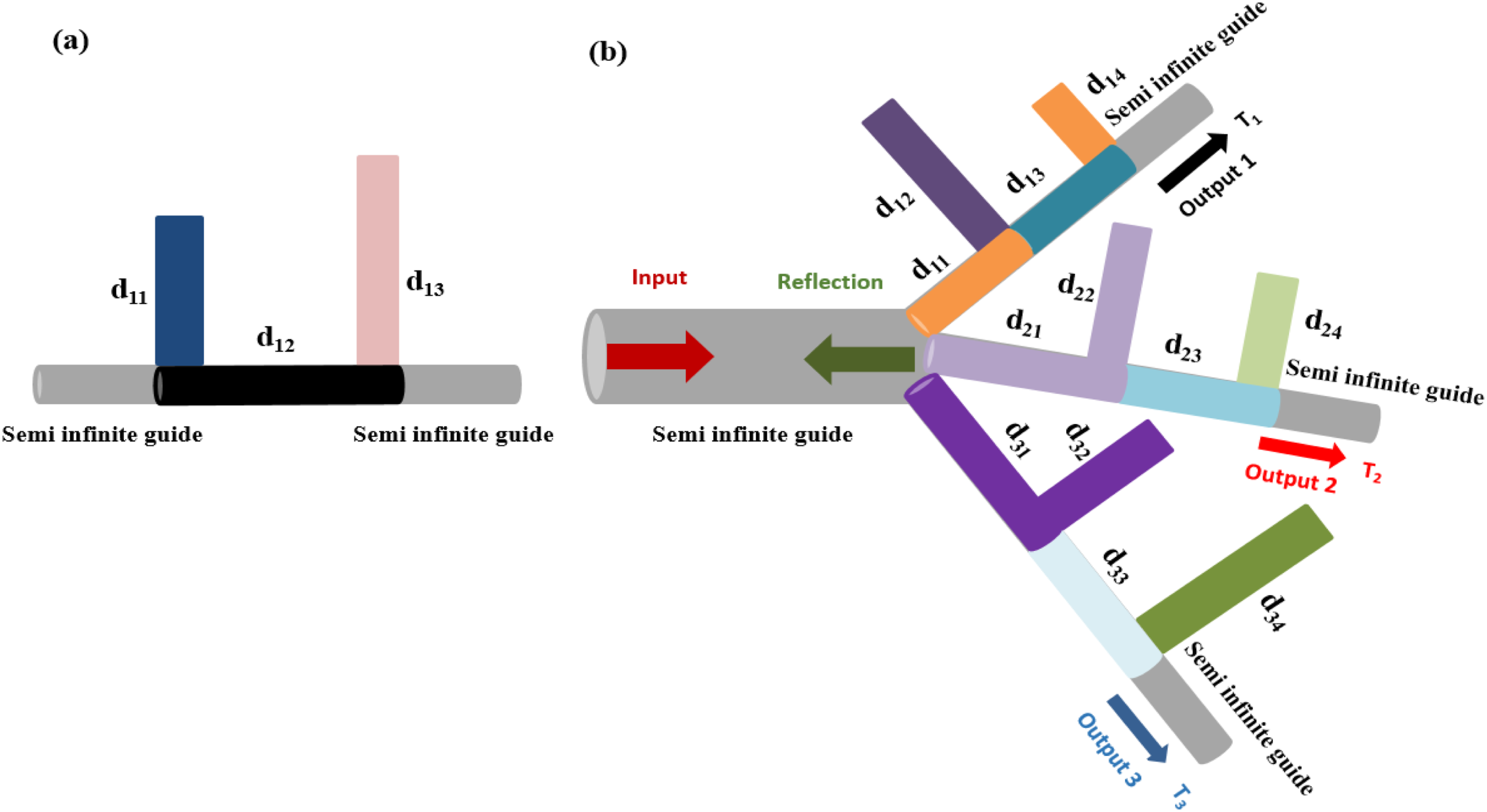
Theoretical analysis
Transmission and reflection coefficients through a simple structure composed of two grafted resonators at two sites
Our theoretical analysis is performed with the help of the interface response theory62,63 of continuous media, which allows to calculate the Green function of any composite materials, as well as the transmission and reflection rates. The simple structure presented in this work (Figure 1(a)) is composed of two grafted resonators at the sites 0 and 1. Each resonator induces zero of transmission. Between the two zeros of transmission, the global system induces a complete transmission following an AIT type resonance. We obtain a Fano type resonance if the two grafted resonators have the same lengths. To visualize these resonances in our structure, we calculate the transmission and reflection coefficients. In this case, it is helpful to know the Green function of its elementary constituents (finite segment of length d12, the resonators of lengths d11 and d13 and semi-infinite guides).
The inverse Green function of semi-infinite waveguides constituting the input and the output lines is given by:

The Green function of a finite segment of length d12 is a matrix
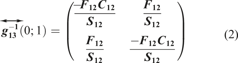
While the inverse Green function of the closed resonators


With:
We suppose all that the guides and resonators have the same characteristics (i.e., Fs = F11 = F12 = F13 = F).
The Green’s function of the whole system in the interface space M = {0,1} can be obtained from a linear superposition of the above inverse Green’s functions of the constituent:

The transmission coefficient through the structure is given by the following expression:

From the expression of t (equation (5)), one can deduce the transmission rate as follows:


From the expression of r (equation (7)), one can deduce the reflection rate:

One can show easily the conservation energy, namely:

Transmission and reflection coefficients through a phononic demultiplexer contains three channels
In this part, we consider the structure shown in Figure 1(b), this structure is composed of an input line and three output lines, all fixed at point 1. The first output contains a length d11 and two resonators of lengths d12 and d14 separated by a distance d13. Likewise, the second output line contains a length d21 and two resonators of lengths d22 and d24 separated by a distance d23. Similarly, the third output contains a length d31 and two resonators of lengths d32 and d34 separated by a distance d33. As mentioned above, the U-shaped resonator along a waveguide was the subject of several studies in acoustics by different authors.25,27 In particular, this structure can present two types of resonances: AIT type resonance when the two resonators have different lengths and Fano type resonance when the two resonators have the same lengths. For simplicity, all waveguides are assumed being characterized by the same characteristic impedance
The inversed Green function of the three semi-infinite waveguides:

The inversed Green function of finite segments (d11 and d13) in the interface spaces {1,2} and {2,3} along the first output line
49
:

The inversed Green function of the closed resonators


The inversed Green function of finite segments (d21 and d23) in the interface spaces {1,4} and {4,5} along the second output line
49
:

The inversed Green function of the closed resonators


The inversed Green function of finite segments (d31 and d33) in the interface spaces {1,6} and {6,7} along the third output line
49
:

The inverse Green function of the closed resonators


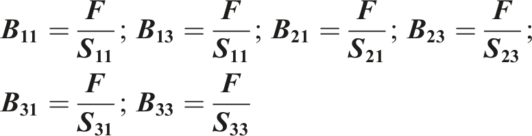
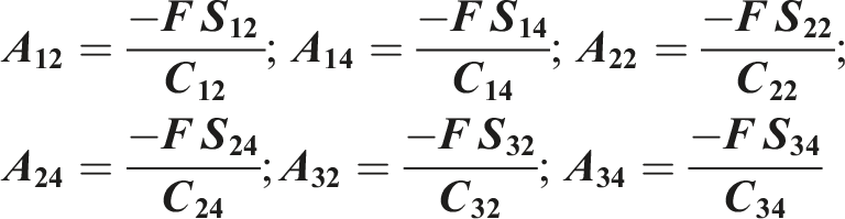
The linear superposition of the inversed Green functions of the previous constituents gives us the inversed Green function of the composite structure in the interface spaces M’ = {1,2,3,4,5,6,7}:


The reflection coefficient in the input line of the phononic demultiplexer (Figure 1(b)) is given by:

The expression of the reflection rate R in the input line is given by:

The transmission coefficients in the first, second and third output lines are given respectively by:






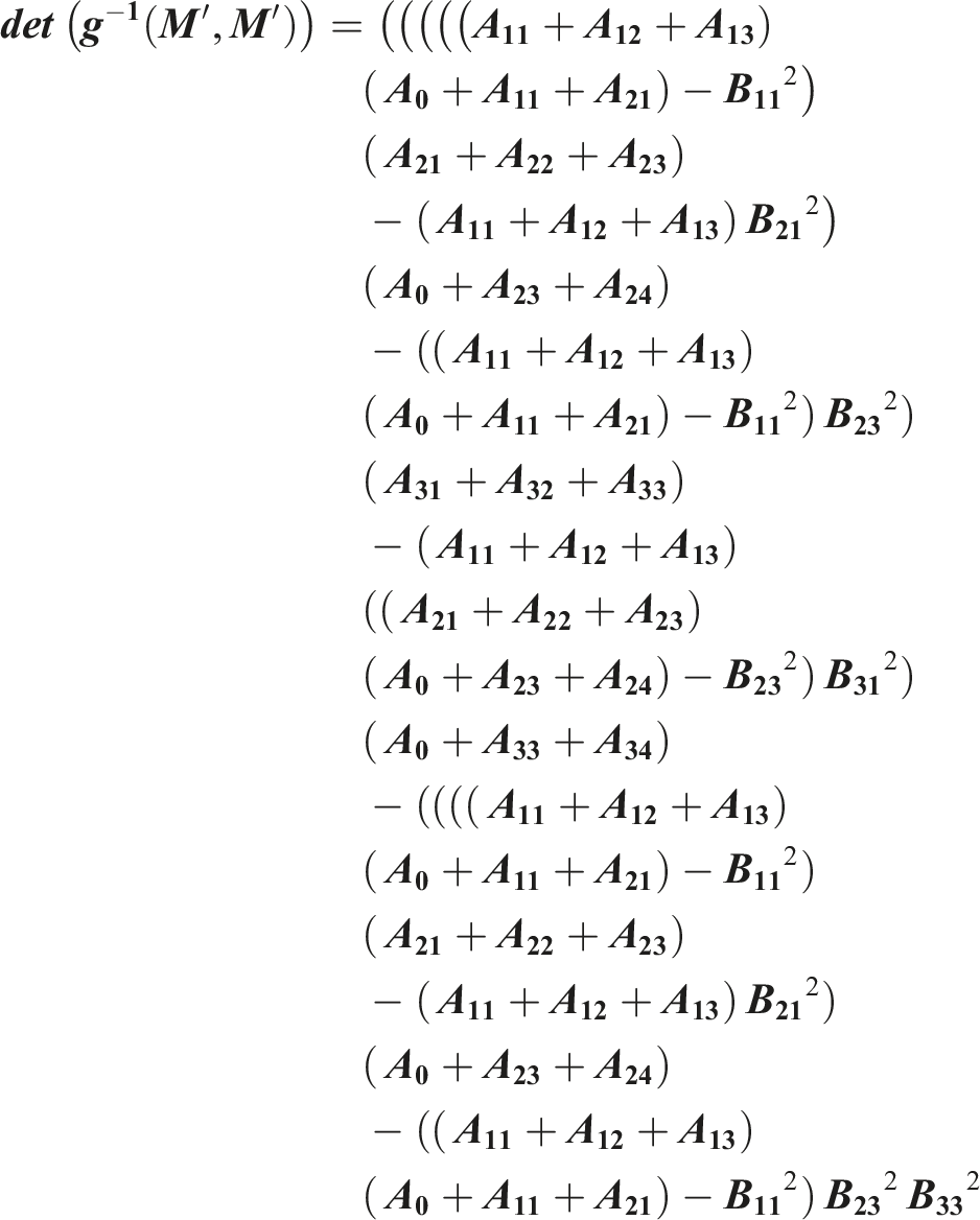
The transmission rates in the three output lines are given respectively by:

The transmission and reflection rates that satisfy the energy conservation:

Results and discussions
AIT and fano resonances in the U structure
Before discussing the problem of the whole structure described above (Figure 1(b)), let us first recall briefly the results of a particular case (two resonators grafted at two sites different) which is necessary to understand the acoustic wave propagation in the structure shown in Figure 1(a) in order to obtain the Fano and AIT resonances in slender tubes. Figure 2 gives the variation of the transmission T and reflection R rates as a function of the reduced frequency Ω (Ω = Variation of the transmission and reflection rates versus the reduced frequency Color map of the transmission rate as a function of the resonator lengths d11 and d13 with d12 = 1D and 2.9 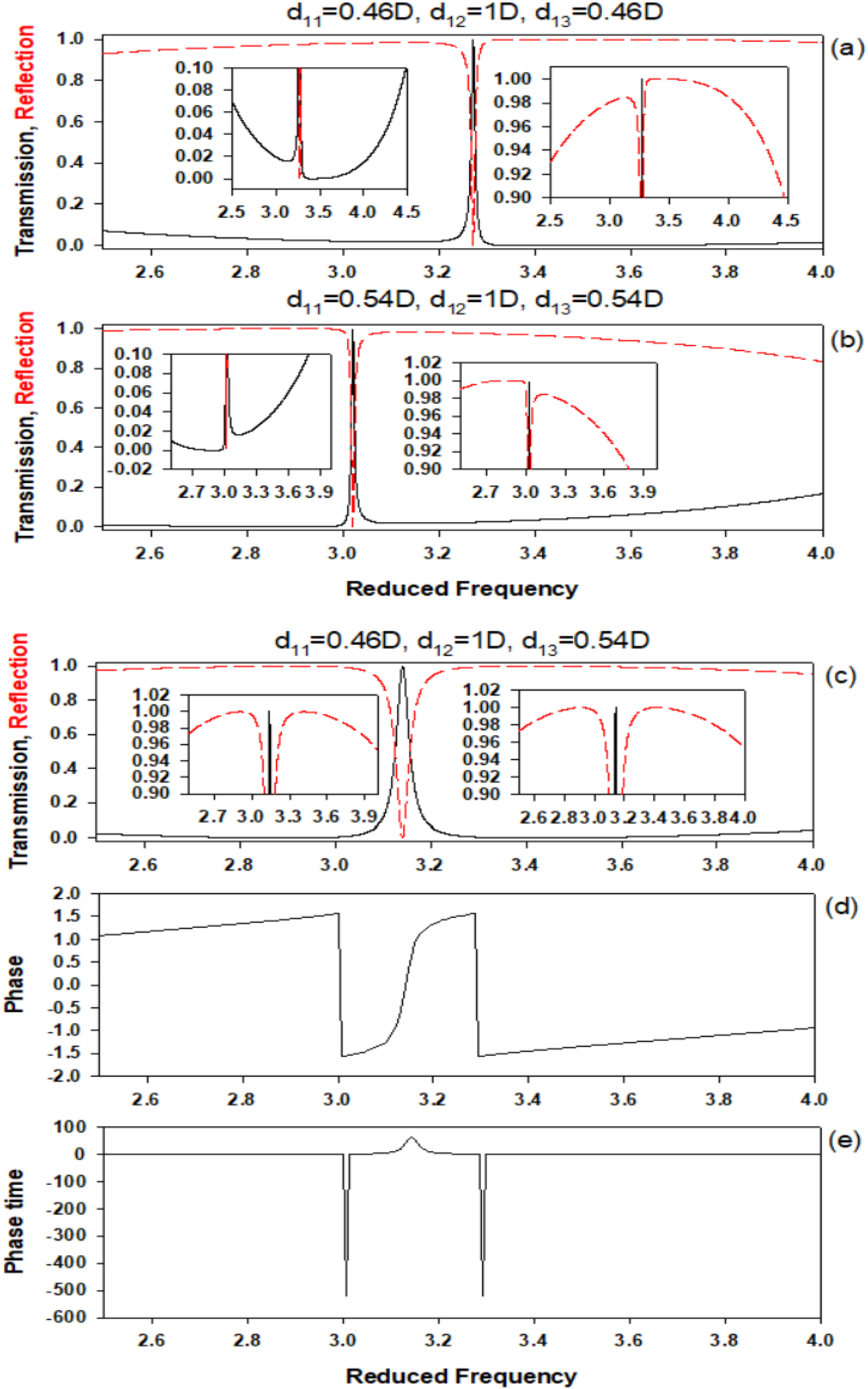
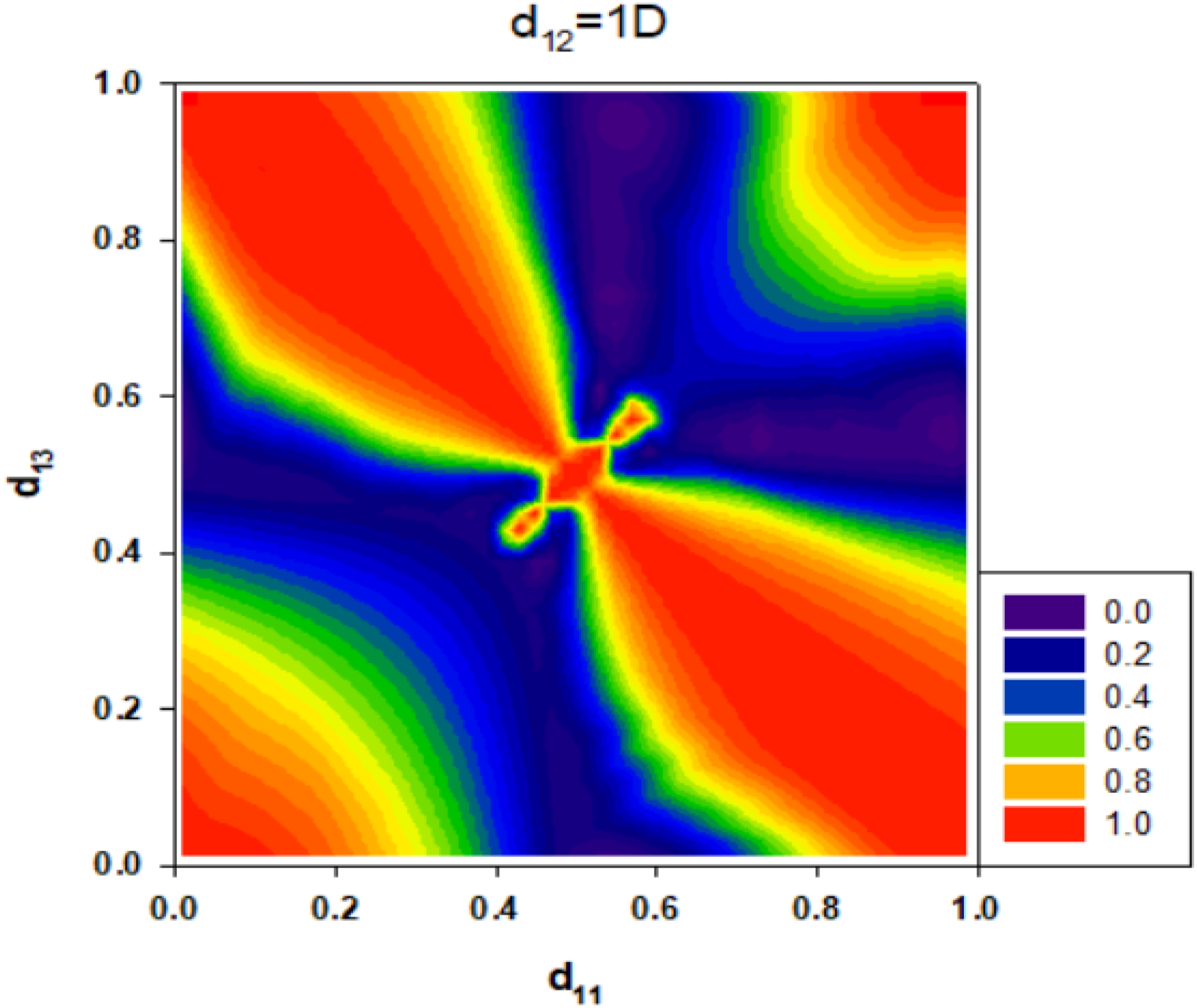
To obtain the adequate geometrical parameters leading to a desirable performance of the studied system, with a high transmission rate of the AIT resonance, we plot the color map of the transmission rate belonging to the reduced frequency Ω interval [2.9-3.4], as a function of resonator lengths d11 and d13 with d12 = 1D. The map below shows that for each point of d11 and d13, we obtain a transmission maximum. Firstly, the red color represents a high transmission rate for different values of resonator lengths. The transmission maxima are symmetrical with respect to the center of resonator lengths (d11 = d13 = 0.5D). In this case, we obtain a Fano resonance when d11 = d13 = 0.46D and d11 = d13 = 0.54D (same lengths of resonators), as well as the AIT resonance is obtained when d12 = 0.46D and d14 = 0.54D (different lengths of resonators). Secondly, the green color indicates a medium transmission rate but the dark blue color indicates the transmission minima in case of the medium values of d11 and d13 (0.4D<d11 < 0.6D and 0.4D<d13 < 0.6D). To summarize, the ideal situation to operate on is the first one (red color) because the transmission rate has a maximum value. As for the last one (dark blue color), the performed system could be used as a total reflection filter.
Demultiplexer based on
structure
In this part, we consider the
Demultiplexer based on fano resonances
As mentioned in reference 25, in order to achieve a Fano resonance, we should take two identical lengths of resonators, but slightly different from d13/2 (i.e., d12 = d14≠d13/2) along the first output line. Similarly, we should take d22 = d24≠d23/2 along the second output line and we should take d32 = d34≠d33/2 along the third output line. The explicit expressions of the twelve different lengths d11, d12, d13, d14, d21, d22, d23, d24, and d31, d32, d33, d34 should satisfy the following equations in order to obtain a total transmission rate along one output line by keeping the other lines unaffected:



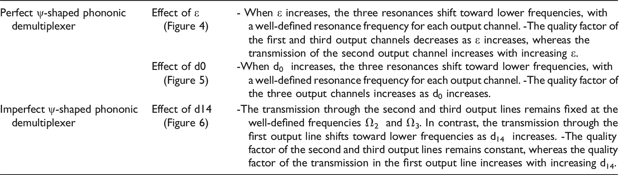
In this part, we study on one hand the evolution of the reduced frequency Ω of Fano resonances versus the parameter ϵ with d0 = 1.3D (Figure 4(a)). The Fano resonances get closer to each other along the output lines when ϵ takes low values (0D (a) Evolution of the reduced frequency as a function of the parameter ϵ with d0 = 1.3D. Evolution of the transmission rates T1, T2 and T3 as a function of the reduced frequency for ϵ = 0.05D (b), ϵ = 0.091D (c) and ϵ = 0.121D (d).
On the other hand, we present in Figure 5 a the variation of the reduced frequency Ω as a function of the parameter d0. We remark that the Fano type resonances decrease to low frequencies with the variation of d0. Figure 5b–(d) indicate the variation of the transmission rates T1, T2 and T3 as a function of the reduced frequency for three values of d0 with ϵ = 0.0925D. We can see that for d0 = 1.3D, the transmission along the first output line (black curve) reaches unity (T1 = 1) at Ω = 2.54, the transmission along the second and third output lines T2 (red curve) and T3 (Blue curve), and the reflection R are cancelled (i.e., T2 = T3 = R = 0). Similarly, when the transmission along the second line (red curve) reaches unity (T2 = 1) at Ω = 2.35, the transmission along the first and third lines T1 (black curve) and T3 (Blue curve) and the reflection R vanish (i.e., T1 = T3 = R = 0). Similarly, when the transmission along the third output line (Blue curve) reaches unity (T3 = 1) at Ω = 2.16, the transmission along the first and second lines T1 (black curve) and T2 (red curve) and the reflection R are cancelled (i.e., T1 = T2 = R = 0). We have seen that this Fano resonance is very sensitive to the parameter d0 and specially the resonator length. The full width at half maximum of the Fano resonances depend strongly on the difference between the resonator lengths. For example, the quality factor of the Fano resonance along the first output line is very high when the parameter d0 = 0.9D. Similarly, the quality factors of the Fano resonances along the second and third output lines are very high when the parameter d0 = 1.3D. The results presented in this section can be easily studied and similar to those found by Mouadili et al when they studied acoustic demultiplexer based on Fano and AIT resonances in slender tubes.
47
(a) Evolution of the reduced frequency as a function of the parameter d0 with ϵ = 0.0925D. Evolution of the transmission rates T1, T2 and T3 as a function of the reduced frequency for d0 = 0.9D (b), d0 = 1D (c) and d0 = 1.3D (d).
To realize a perfect phononic demultiplexer with a high performance (i.e., total transmission along each output line with a high quality factor), it is necessary that equations (15)–(17) must be satisfied. However, if one of the above conditions is not satisfied, the transmission rate cannot reach unity and the demultiplexer becomes imperfect. Figure 6 gives an example making it possible to explain this deviation from perfect demultiplexing when we choose the same parameters as those of Figure 5(d), except varying d14. We show in Figure 6 a the variation of the reduced frequency Ω as a function of the resonator length d14, we take d0 = 1.3D and ϵ = 0.0925D. The first, second, and third output lines are indicated by black, red, and blue curves, respectively. We note that the transmission maximums along the second and third output lines remain constant for two reduced frequencies (Ω = 2.16 for the blue line and Ω = 2.35 for the red line) with the variation of the resonator length d14, this is due to the constant parameter of d0 and ϵ, which means that the lengths of guides and resonators along the second and third output lines are constant and finally the fano type resonances fall at the same frequencies in the second and third channels. Therefore, if we change the resonator length d14, the Fano type resonance moves towards low frequencies. Then, we present in Figure 6(b)–(d) the variation of the transmission rates T1, T2 and T3 as a function of the reduced frequency for different values of the resonator length d14 with d0 = 1.3D and ϵ = 0.0925D. One can notice that the transmission in the first output line (black curve) does not reach unity at Ω = 2.86 (for d14 = 0.4D) and Ω = 2.79 (for d14 = 0.5D), but we observe that the transmission T1 reaches unity when the resonator length d14 takes the value 0.7D. Indeed, the two fano type resonances keep the same reduced frequency along the second and third output lines with high transmission rates (T2 = T3 = 1) and good quality factors for the ideal parameters of d0 and ϵ. (a) Evolution of the reduced frequency as a function of the parameter d14 with ϵ = 0.0925D and d0 = 1.3D. Evolution of the transmission rates T1, T2 and T3 as a function of the reduced frequency for d14 = 0.4D (b), d14 = 0.5D (c) and d14 = 0.7D (d).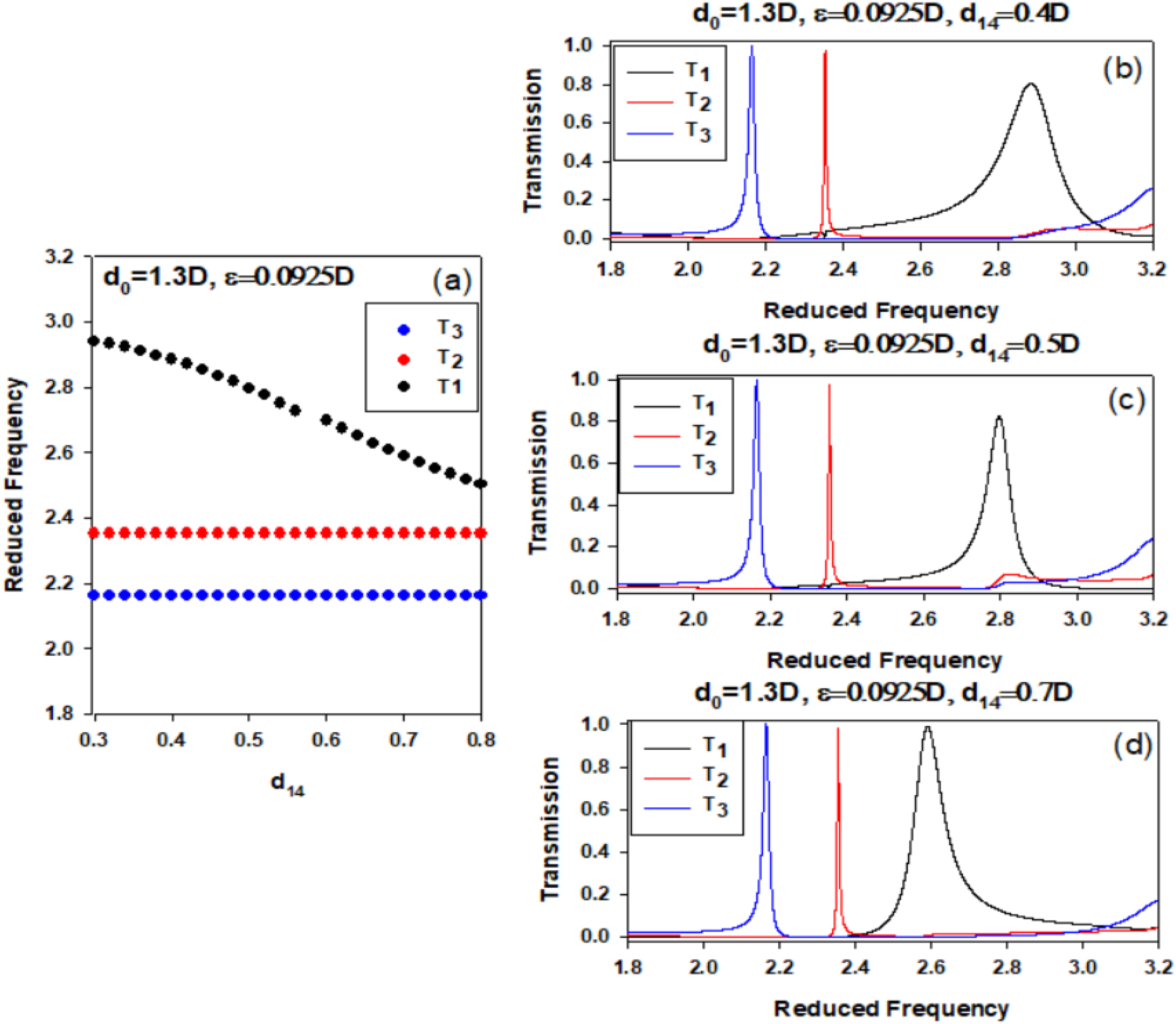
Demultiplexer based on AIT resonances
As already demonstrated in previous works,25,27 in order to achieve an AIT resonance with such structures, we should take two different lengths of resonators along each output line (i.e., 


Figure 7(a)–(f) present the variation of the transmission rates T1 (black curve), T2 (red curve) and T3 (blue curve) as a function of the reduced frequency Ω for different values of ϵ with d0 = 0.875D. We can see that for each value of ϵ, when the transmission along the first output line reaches unity (T1 = 1), the transmission along the second and third output lines cancel out each other (i.e., T2 = T3 = 0). Similarly, when the transmission along the second output line reaches unity (T2 = 1), the transmission along the first and third output lines vanish (i.e., T1 = T3 = 0). Similarly, when the transmission along the third output line reaches unity (T3 = 1), the transmission along the first and second output lines vanish (i.e., T1 = T2 = 0). We observe that the AIT resonance in the first output line falls at the same frequency for all values of the parameter ϵ, its width decreases as ϵ decreases and disappears for ϵ = 0, giving rise to detuned of resonators. As ε→0, the detuning vanishes and the destructive interference of the coupled modes becomes perfect, leading to a vanishing linewidth (Q→∞). This behavior reflects the theoretical limit of AIT resonances, where perfectly matched resonators produce extremely sharp, high-Q spectral features. In addition, the shape and width of the AIT resonance change slightly when ϵ becomes negative (i.e., for a permutation of both resonators lengths di2 and di4). The position and width of the AIT resonances along the second and third output lines strongly depend on the parameter ϵ. When ε≠0, the detuning ε breaks the symmetry of the system, resulting in asymmetric splitting of the resonances. This explains why the second and third channels shift differently. Indeed, the first AIT resonance (black curve) has two transmission zeros around a maximum transmission peak at Ω = 3.59, the positions of the second and third AIT resonances (red and blue curves) fall above Ω = 3.6 for ϵ > 0 and disappear for ϵ = 0. Similarly, the second and third AIT resonances fall below Ω = 3.59 for ϵ < 0 and disappear for ϵ = 0. We point out that the AIT resonance along the first output line falls at the same frequency whatever the value of ϵ, whereas the AIT resonances along the second and third output lines are asymmetrical with respect to the center of the parameter ϵ (opposition of the AIT resonance when ϵ becomes negative). So, the AIT resonance along the second and third output lines move towards the high frequencies from ϵ > 0, and move towards the low frequencies from ϵ < 0 and disappear from ϵ = 0. Also, the variation of the quality factors Q of the three AIT resonances in the three outputs lines increases when the absolute value of ϵ decreases. Evolution of the transmission rates T1, T2 and T3 as a function of the reduced frequency for ϵ = 0.01D (a), ϵ = −0.01D (b), ϵ = 0.05D (c), ϵ = −0.05D (d), ϵ = 0.08D (c) and ϵ = −0.08D (f). (g) Evolution of the reduced frequency as a function of the parameter ϵ with d0 = 0.875D.
These results are summarized in Figure 7(g) where we plot the frequencies of three AIT resonances as a function of the parameter ϵ. The frequencies of three AIT resonances depend on the parameter ϵ. Also, the quality factors of the three AIT resonances are high and tend to infinity when ϵ tends to zero. These results are original and identical to those obtained by Mouadili et al. 47
On the other hand, we present in Figure 8a–(d) the variation of the transmission rates T1, T2 and T3 as a function of the reduced frequency Ω for different values of d0 with ϵ = 0.01D. We remark that the AIT resonances decrease to low frequencies with the increase d0. We can see that for each value of d0, the transmission along the first output line (black curve) reaches unity (T1 = 1), the transmission along the second and third output lines T2 and T3 (red and Blue curves) and the reflection R vanish (i.e., T2 = T3 = R = 0). The conservation energy (T1+T2+T3+R = 1) must be satisfied for each output line. We can see that the frequencies of AIT resonances depend on the parameter d0. Also, the quality factors of the three resonances are almost identical. Evolution of the transmission rates T1, T2 and T3 as a function of the reduced frequency for d0 = 0.5D (a), d0 = 0.65D (b), d0 = 0.8D (c) and d0 = 0.95D (d) with ϵ = 0.01D.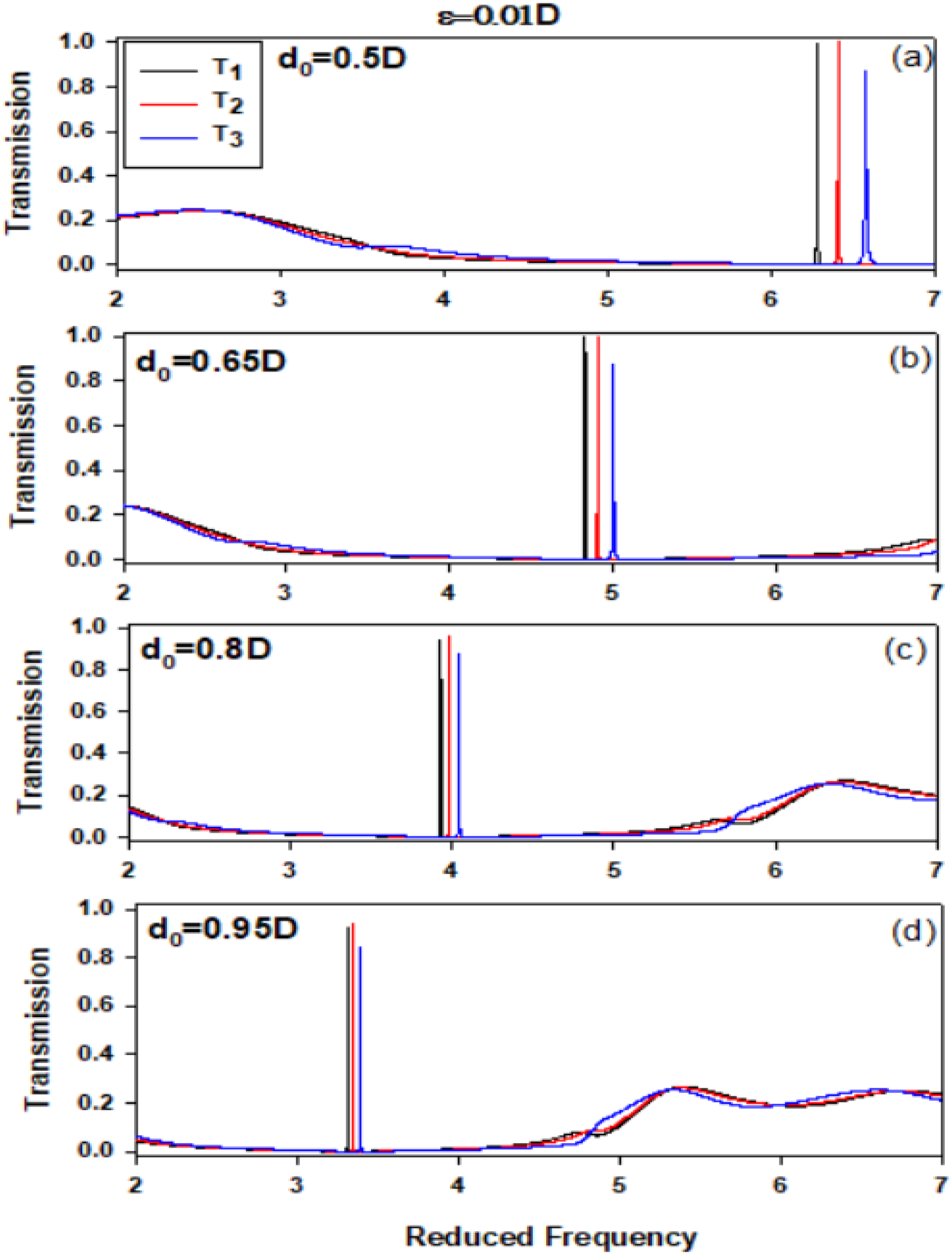
To achieve an AIT type resonance with high performance (i.e., total transmission along each output line with a high quality factor), it is necessary that equations (18)–(20) must be satisfied. However, if one of the above conditions is not satisfied, the transmission rate cannot reach unity and the phononic demultiplexer becomes imperfect. Figure 9 gives an example making it possible to explain this deviation from a perfect demultiplexer when we choose the same parameters as those of Figure 7(c), except varying d22. We show in Figure 9 a the variation of the reduced frequency Ω as a function of the resonator length d22, we take d0 = 0.875D, ϵ = 0.05D and d14 = 0.42D. The transmission maximum along the first, second and third output lines are indicated by the black, red and blue curves, respectively. We note that the transmission maximums along the first and third output lines remain constant for two reduced frequencies (Ω = 3.57 for the black line and Ω = 4.11 for the blue line) with the variation of the resonator length d22, this is due to the constant parameter of d0 and the parameter ϵ which means that the lengths of guides and resonators along the first and third output lines are constant, and finally the AIT type resonances fall at the same frequencies. Therefore, if we change the resonator length d22, the AIT type resonance moves towards low frequencies. Then, we present in Figure 9b–(c) the variation of the transmission rates T1, T2 and T3 as a function of the reduced frequency Ω for two values of the resonator length d22 with d0 = 0.875D and ϵ = 0.05D. We notice that the transmission in the third output line (black curve) does not reach unity at Ω = 4.11 for d22 = 0.13D and d22 = 0.43D, but the transmission T2 reaches unity when the resonator length d22 = 0.43D. The AIT resonance along the first output line reaches unity (T1 = 1) and remains constant for Ω = 3.57 with a high transmission rate. It is noted that the filtered resonance has a shape of AIT type resonance. The width at the half maximum of the AIT resonances depends strongly on the parameters d0 and ϵ. Our finding agrees with that obtained by A. Mouadili et al.3,66 (a) Evolution of the reduced frequency as a function of the resonator length d22 with d0 = 0.875D, ϵ = 0.05D and d14 = 0.42D. Evolution of the transmission rates T1, T2 and T3 as a function of the reduced frequency for d22 = 0.13D (b) and d22 = 0.43D (c).
In summary, low crosstalk and high quality factor67,68 ensure clear channel separation and minimize signal degradation, which is essential for demultiplexer efficiency in phonon routing applications.
Conclusion
In this research, we have studied a
Footnotes
Appendix
Finally, we present in the Table 1 the comparaison summary of different demultiplexer systems that are cited in the part of references [69,70,71,72,73,74]. Comparative summary of recent demultiplexer systems.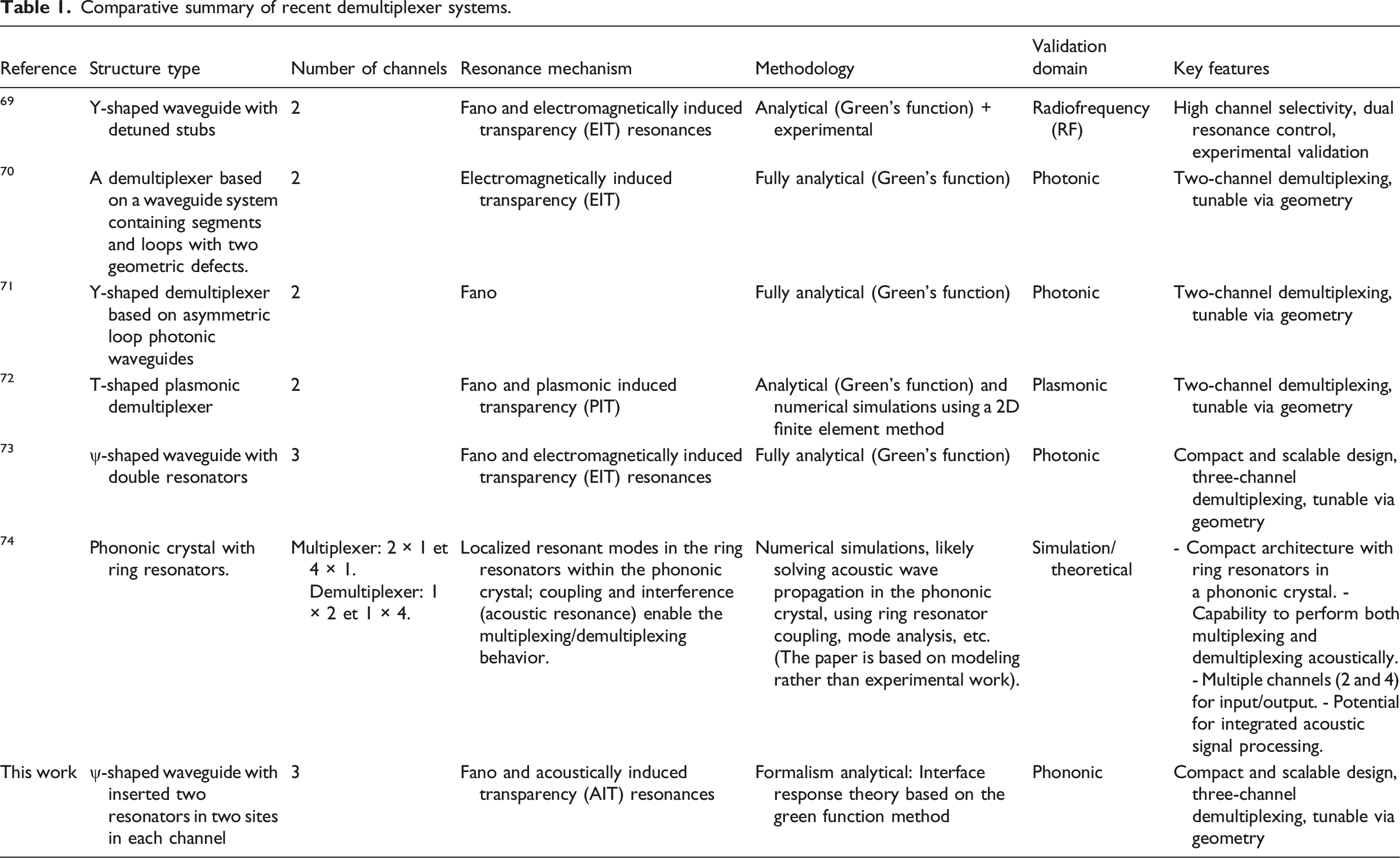
Reference
Structure type
Number of channels
Resonance mechanism
Methodology
Validation domain
Key features
69
Y-shaped waveguide with detuned stubs
2
Fano and electromagnetically induced transparency (EIT) resonances
Analytical (Green’s function) + experimental
Radiofrequency (RF)
High channel selectivity, dual resonance control, experimental validation
70
A demultiplexer based on a waveguide system containing segments and loops with two geometric defects.
2
Electromagnetically induced transparency (EIT)
Fully analytical (Green’s function)
Photonic
Two-channel demultiplexing, tunable via geometry
71
Y-shaped demultiplexer based on asymmetric loop photonic waveguides
2
Fano
Fully analytical (Green’s function)
Photonic
Two-channel demultiplexing, tunable via geometry
72
T-shaped plasmonic demultiplexer
2
Fano and plasmonic induced transparency (PIT)
Analytical (Green’s function) and numerical simulations using a 2D finite element method
Plasmonic
Two-channel demultiplexing, tunable via geometry
73
ψ-shaped waveguide with double resonators
3
Fano and electromagnetically induced transparency (EIT) resonances
Fully analytical (Green’s function)
Photonic
Compact and scalable design, three-channel demultiplexing, tunable via geometry
74
Phononic crystal with ring resonators.
Multiplexer: 2 × 1 et 4 × 1. Demultiplexer: 1 × 2 et 1 × 4.
Localized resonant modes in the ring resonators within the phononic crystal; coupling and interference (acoustic resonance) enable the multiplexing/demultiplexing behavior.
Numerical simulations, likely solving acoustic wave propagation in the phononic crystal, using ring resonator coupling, mode analysis, etc. (The paper is based on modeling rather than experimental work).
Simulation/theoretical
- Compact architecture with ring resonators in a phononic crystal. - Capability to perform both multiplexing and demultiplexing acoustically. - Multiple channels (2 and 4) for input/output. - Potential for integrated acoustic signal processing.
This work
ψ-shaped waveguide with inserted two resonators in two sites in each channel
3
Fano and acoustically induced transparency (AIT) resonances
Formalism analytical: Interface response theory based on the green function method
Phononic
Compact and scalable design, three-channel demultiplexing, tunable via geometry
Declaration of conflicting interests
The authors declared no potential conflicts of interest with respect to the research, authorship, and/or publication of this article.
Funding
The authors received no financial support for the research, authorship, and/or publication of this article.
