
Abstract
Vibration pads are one of the important functions in rotating equipment, one of which is a washing machine that has two frequency modes. This study investigates the effectiveness of vibration damping devices in the form of vibration pads installed on household washing machines by implementing two models of auxetic metamaterials geometry combinations. Comparative tests were carried out in conditions with and without damping at two frequency categories, high and low. Data processing of the test results was carried out using Matlab. In terms of displacement, a reduction of 28% when the machine is started and up to 60% during stable operation was observed. However, low-frequency testing produced less effective values. Further analysis using Fast Fourier Transform (FFT) and Short-Time Fourier Transform (STFT) confirmed that the dominant vibration frequency ranged from 18 to 24 Hz, with consistent spectral patterns and transient behavior only appearing during the machine start-up phase. These findings underscore the potential of vibration damping in improving the dynamic stability of washing machines and highlight the importance of targeted damping system design for effective vibration mitigation in a specific frequency range.
Introduction
Vibration control holds significant importance across a broad spectrum of engineering fields, including mechanical, aerospace, civil, and biomedical engineering. 1 Vibrations, when not properly managed, can lead to structural fatigue, noise pollution, and even catastrophic failure in sensitive systems. Therefore, effective vibration mitigation is essential to ensure safety, comfort, and longevity of both mechanical systems and structural components. 2 Throughout history, humans have devised various solutions to control and minimize unwanted vibrations. These range from large-scale structural modifications to protect buildings from seismic activity to intricate damping mechanisms in aerospace systems, and even subtle applications in biomedical devices like prosthetics and orthotics where controlled energy dissipation improves user comfort and function.3,4
Recent developments have seen a surge in the use of advanced and smart materials for damping purposes. Natural fibers, for instance, are gaining attention for their sustainability and cost-effectiveness, while smart materials such as magnetorheological elastomers and piezoelectric composites offer dynamic control capabilities that adapt in real time to environmental stimuli. 5 Despite these advancements, limitations still exist in terms of material cost, complexity of fabrication, and adaptability for consumer-level applications. A particularly promising direction in vibration control is the implementation of metamaterials. Metamaterials are artificially engineered structures designed to achieve properties not typically found in natural materials. Their performance arises primarily from their internal geometrical design rather than their base material properties.6–8 Among the most notable types of metamaterials is the class known as auxetic metamaterials, which exhibit a negative Poisson’s ratio meaning they expand laterally when stretched and contract laterally when compressed, contrary to most natural materials. 8
This unique deformation behavior is not only counterintuitive but also beneficial for applications involving energy absorption, indentation resistance, and shear stiffness enhancement. Auxetic behavior is typically achieved by tailoring the microstructure of a material using patterns such as re-entrant honeycombs, 9 bowtie structures, 10 and other lattice-based topologies like double-V or star-shaped units. 11 These structures enable significant mechanical responses that can be customized depending on the desired performance characteristics.
Auxetic metamaterials have been widely explored for use in biomedical implants, protective equipment, aerospace panels, and even acoustic dampers.12–15 Their excellent energy dissipation and impact absorption properties make them ideal for environments where both stiffness and flexibility are required. In recent years, researchers have demonstrated the potential of auxetic structures in prosthetic design, where their deformation under load mimics the natural movement of human limbs and improves user experience during ambulation. In addition to these advanced applications, there is growing interest in exploring the feasibility of auxetic metamaterials for more common, day-to-day uses, particularly in the realm of household appliances and consumer goods. 6
One such application is the vibration damping of washing machines. Vibration in washing machines can cause excessive noise, reduce the lifespan of internal components, and even result in movement across the floor during operation. Traditionally, rubber pads or spring-damper systems are used to absorb vibration. However, these solutions may be less effective over time due to material fatigue or wear. By introducing auxetic metamaterials into the damping system of a washing machine, a more resilient and efficient vibration absorption mechanism could be realized.16–19
This paper explores the feasibility of using auxetic structures as vibration dampers for household appliances, using a washing machine as a case study. Such a direction is rarely addressed in current literature, where most applications of metamaterials are focused on industrial or medical-scale devices. The exploration of mundane, everyday use cases is essential in order to broaden the practical impact of metamaterials and push the boundaries of their commercial applicability.
To that end, we designed and fabricated an auxetic damper based on an inverted hexagonal (bowtie) structure. The damper was produced using Fused Deposition Modeling (FDM) 3D printing with polyurethane (PU) filament, chosen for its elastomeric properties and ease of fabrication. The effectiveness of this auxetic damper was then evaluated and compared against traditional damping methods namely, no damper and a non-auxetic damper design. The results are expected to show that the auxetic design provides superior vibration attenuation due to its enhanced deformation mechanism and energy absorption characteristics. Additionally, the study serves as a foundation for future works to explore other household applications of metamaterials, such as in furniture, floor underlayments, or electronics casings.
By investigating the performance of auxetic metamaterials in everyday applications, we aim to contribute to a broader understanding of their capabilities and to encourage further interdisciplinary research. As more fabrication techniques become accessible, particularly 3D printing and low-cost prototyping, the possibility of integrating smart geometrical designs into consumer-level products becomes increasingly feasible. This research not only advances the scientific discourse on auxetic metamaterials and their functional capabilities but also bridges the gap between high-end engineering applications and household utility. It opens up a new realm of possibilities for using tailored material geometry to solve practical, real-world problems in an efficient and innovative manner.
Materials and methods
Structure design
Basic geometry of inverted honeycomb was adopted in the design for the structure of the auxetic damper. It consisted of two main structures working separately in lateral and axial direction, along with those a circular cavity has also been prepared for the footing of the washing machine to be inserted. Figure 1 and 2 highlighted the design and each of its features. Design geometry of mechanical auxetic metamaterials vibration pad. Overall dimension and section view design.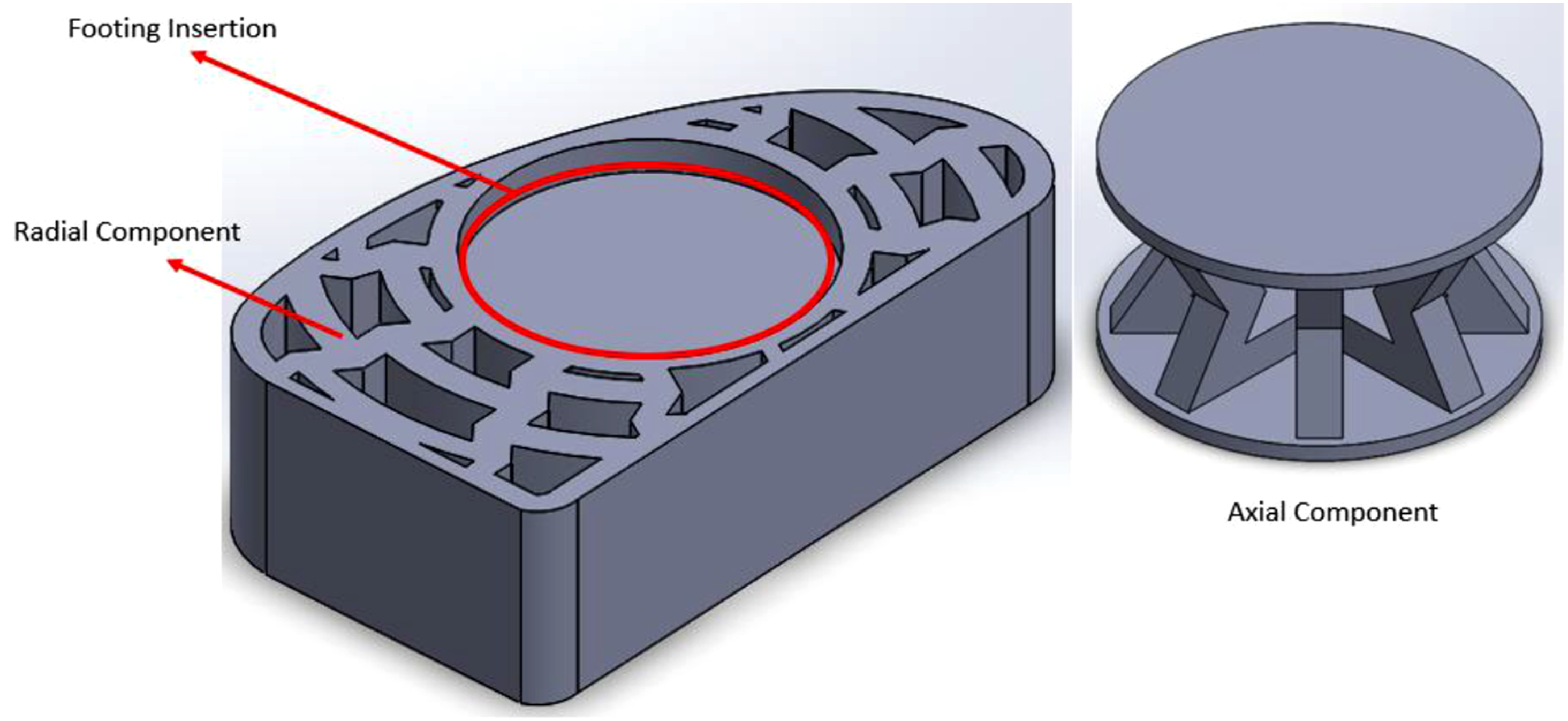

For the lateral component, series of inverted hexagonal honeycomb structures are patterned radially expanding from the center of the insertion cavity for the washing machine footings. For a honeycomb plate, the patterns are usually made following linear direction, but to dampen the vibration generated during machine active rotational work of motion. 10 Lastly, to support the weight of the washing machine during both usage and out of use, another set of auxetic structure following the same design principle of inverted honeycomb was implemented and located right below the insertion cavity for washing machine’s footing. It consisted of 8 pieces of ligaments pattered in circular manners. In total, there are four damper units being used equal to the amounts of footing available on the washing machine.
The choice of inverted honeycomb geometry is grounded in the auxetic property it offers, specifically the negative Poisson’s ratio behavior where the material expands laterally when stretched and contracts laterally when compressed. This behavior is particularly beneficial for damping because it allows for enhanced energy absorption and load distribution compared to conventional materials. In recent studies, various auxetic designs such as re-entrant honeycombs, missing-rib models, and rotating units have shown potential in vibration isolation systems.10–13 Among these, the inverted honeycomb structure has been highlighted for its manufacturability, structural integrity, and stable deformation mechanism under dynamic loading.
The radial arrangement of auxetic cells in the lateral component plays a vital role in mitigating the multidirectional vibration induced by unbalanced drum rotations. Rather than focusing energy dissipation along a single axis, this design enables isotropic response around the central axis of the damper. This isotropic behavior was also observed by,14,20,21 who demonstrated that radial auxetic lattices are capable of distributing mechanical stress evenly across their surface under multi-axial loading.
On the other hand, the axial structure serves the dual function of load bearing and vibration attenuation in the vertical direction. The eight-ligament design follows a symmetrical pattern ensuring uniform support for the washing machine’s weight. Each ligament undergoes compressive deformation when subjected to vertical loads, leading to an inward expansion of the structure, enhancing the damping response and providing stiffness tuning capability. This mechanism is especially useful in reducing the transmission of shock or vibratory loads to the underlying floor, thereby increasing user comfort and reducing noise levels. Moreover, the use of modular design in the damper system consisting of four identical units provides flexibility in assembly and ease of replacement. This modularity also enables scalability for use in appliances of different sizes and weights. In future implementations, the mechanical performance of each module could be tailored by varying the ligament thickness, unit cell angles, or material stiffness, enabling customized damping responses for specific applications.
The material used for the fabrication, polyurethane (PU), was selected due to its flexibility, resilience, and compatibility with fused deposition modeling (FDM) 3D printing. PU’s viscoelastic properties inherently contribute to damping performance, and when combined with auxetic geometry, result in a synergistic enhancement of energy dissipation capabilities. Auxetic PU-based lattice structures fabricated through additive manufacturing exhibit significant potential in impact resistance and vibration control applications. The damper structure leverages the unique properties of auxetic inverted honeycomb geometry by integrating separate lateral and axial working elements. The radially arranged auxetic pattern ensures effective lateral vibration mitigation, while the circularly arranged axial ligaments provide robust vertical load support. Together, they offer a comprehensive vibration control mechanism suitable for household applications such as washing machines. This design not only highlights the practical feasibility of applying auxetic metamaterials in everyday life but also opens up avenues for further exploration in low-cost, high-efficiency damping systems using advanced materials and manufacturing technologies.
Pad fabrication method
Based on the previously discussed design configuration, the slicing process for 3D printing was conducted using Ultimaker Cura, a widely adopted slicing software compatible with Fused Deposition Modeling (FDM) printers. The selected material for fabrication was polyurethane (PU) filament, chosen for its rubber-like mechanical behavior and elasticity, which makes it particularly suitable for damping applications. Unlike conventional rubber materials that require mold-based casting processes often costly and complex PU filament offers easier handling and accessibility for additive manufacturing, especially in a prototyping context. This allows for more rapid iterations in research and development, particularly in the context of auxetic structures where design complexity can be high.
To optimize the printing process and reduce the need for additional support structures, the design was modularized into two major subcomponents: the lateral (radial) and the axial components. The radial section was printed as a single unit with minimal overhangs, while the axial component was further divided into upper and lower halves to accommodate the vertical geometry and minimize warping or instability during printing. After fabrication, the two axial halves were adhesively bonded using industrial-grade flexible adhesives to form a single cohesive damping structure.
The use of additive manufacturing, particularly FDM 3D printing, as a fabrication technique for vibration damping structures is still relatively novel and evolving. Despite its advantages in geometric flexibility and reduced tooling costs, there remain some challenges associated with material limitations and structural integrity. One of the key limitations lies in the types of materials that can be effectively utilized with this method. While polymers such as PLA, ABS, and TPU are widely available for FDM, the integration of advanced materials such as metals and composites into the 3D printing process is still under active development. Issues related to melting point, viscosity during extrusion, and post-processing requirements make metal-based 3D printing less accessible for everyday engineering applications.
From a material perspective, various substances have been explored for their potential in vibration damping. These include metals, ceramics, polymers, and composites each offering unique mechanical behaviors that influence their damping characteristics. Metals such as shape memory alloys and ferromagnetic alloys have demonstrated excellent vibration damping performance due to their inherent energy dissipation mechanisms through phase transformation or magnetic domain movement.22–25 However, their complexity and cost limit their use in general-purpose applications. 26
Polymers, especially thermoplastics and elastomers, are more commonly used for damping applications due to their lower stiffness, higher elasticity, and energy absorption capacity. Materials like thermoplastic polyurethane (TPU), polytetrafluoroethylene (PTFE), and blends such as polypropylene/butyl rubber or PVC/chlorinated polyethylene have been widely reported in literature for their effectiveness in vibration isolation. PU, in particular, offers a desirable combination of flexibility and resilience, making it an excellent candidate for damping structures fabricated via 3D printing. Other promising developments include interpenetrating polymer networks and nanocomposite structures, which combine polymers with reinforcing agents to enhance both damping performance and mechanical strength.27–32
One crucial aspect of effective damping is the glass transition temperature (Tg) of the material. Polymers with Tg below room temperature typically exhibit rubbery behavior, enabling them to deform and recover efficiently under dynamic loading, which is vital for energy dissipation. Amorphous thermoplastics and elastomers that meet this criterion are particularly interesting for use in vibration damping systems. The ability to fabricate such materials into intricate auxetic geometries through additive manufacturing opens up exciting possibilities for customized damping systems tailored to specific frequencies or operational environments.
The use of 3D printing in the fabrication of vibration damping components also offers substantial advantages in terms of manufacturing efficiency and design freedom. Traditional manufacturing methods often face significant constraints when producing geometrically complex structures such as auxetic metamaterials. Creating molds for such intricate designs is not only expensive but also time-consuming, especially when iterative prototyping is required. In contrast, 3D printing allows for rapid prototyping and on-demand fabrication with minimal material wastage and tooling requirements. This significantly reduces fabrication time and cost, thereby enhancing the feasibility of applying auxetic damping systems in both research and practical engineering applications.
However, it is important to note that the performance of 3D-printed damping structures can vary significantly depending on printing parameters such as layer height, infill density, printing orientation, and bonding between layers. These factors influence the overall mechanical integrity and energy dissipation capacity of the final product. As such, numerical simulations and mechanical testing should always be conducted prior to final manufacturing to predict the performance of the structure and identify potential failure points. This study has also used Matlab as a simulation data processing tool, so that some data can be displayed for further discussion. This predictive capability is particularly valuable when dealing with auxetic designs, where counterintuitive deformation behavior may complicate the design optimization process.33–35
The integration of additive manufacturing using PU material and FDM-based 3D printing presents a practical and efficient method for fabricating complex auxetic structures for vibration damping. The process enables the realization of highly intricate geometries that would be difficult or costly to manufacture using conventional techniques. Combined with careful material selection and simulation-driven design, this approach represents a promising pathway toward the development of advanced damping technologies applicable not only in industrial settings but also in household appliances such as washing machines.
Method
As a critical stage in the development process, numerical simulation was carried out to evaluate the feasibility and effectiveness of the proposed design concept and the selected material. Beyond serving as a preliminary design assessment, the simulation also plays a key role in validating experimental results and bridging the gap between theoretical models and real-world performance. Meanwhile, the auxetic metamaterial structure was designed using the SolidWorks CAD platform, which allowed for precise geometric modeling of the complex inverted honeycomb patterns. Figure 3 shows the illustration of this study. Illustration scheme of the study.
This study was conducted using a twin-tub washing machine with two modes; a washing mode with a frequency of 13 Hz and a drying mode with a frequency of 27 Hz. The mass of the test system was 7 kg, and this condition was carried out without any additional load on the washing machine. Given the characteristics of the washing machine used in this study, the sampling frequency of the test was 100 Hz. The test was conducted in a closed room and safe from other operating devices to ensure that the data collection process was not disturbed. Data collection was carried out using the MXC6655XA accelerometer sensor module which was installed and attached to the top of the washing machine. Testing in the washing mode has two rotation directions, namely clockwise and counterclockwise with a 3-s interval as shown in Figure 7 which shows the results of the rotation pause. While the drying mode only has one rotation direction, namely clockwise. Data collection was carried out alternately for each rotation mode (washing and drying modes). The experimental test scheme is shown in Figure 4 below. Experimental testing setup scheme.
This research employed a hybrid approach, combining both simulation and experimental methods to ensure comprehensive evaluation. In the experimental setup, the auxetic damper was physically tested by installing it beneath the feet of a standard household washing machine. The washing machine was operated under two typical frequency conditions: low-frequency operation during washing cycles, and high-frequency operation during the spinning/drying cycles. The experiment was conducted under two different scenarios: first, with the washing machine operating without any damping device; and second, with four auxetic dampers installed beneath each of the machine’s feet. During both tests, acceleration data were recorded along two principal axes vertical and horizontal using an accelerometer. The acquired data provided detailed insights into the vibrational behavior of the washing machine under each condition. The experimental acceleration signals were then used as input loading conditions in the Matlab. By applying these real-world loads, the simulation was able to replicate the exact vibrational environment experienced by the damping structure. This enabled a detailed comparison between simulated structural responses and experimental performance.
A numerical model is developed in Matlab by representing the washing machine system as a multi-degree-of-freedom (MDOF) mass-spring-damping dynamic system affected by harmonic excitation due to the unbalance of the drum mass during rotation. The governing equations of the system are stated as follows (1):


Description of the equation parameters used.

Through this process, the suitability of the designed auxetic structure in mitigating unwanted vibrations was assessed. Discrepancies between the simulation and experimental results were analyzed to identify potential design improvements or limitations in the modeling assumptions. Ultimately, this integrated approach of experimental testing and numerical simulation provided a holistic understanding of the damper’s performance and demonstrated the practical potential of using auxetic metamaterials in consumer appliance vibration control applications.
Result and discussion
The experimental evaluation was conducted through multiple trials to ensure that the acquired data were stable and repeatable. Each trial produced data on both displacement and acceleration. The acceleration data were recorded along two principal axes, namely the X and Y directions, to capture the full spectrum of horizontal vibrations. In this experiment, data were collected for two distinct rotational conditions of the washing machine: one representing low-frequency rotation and the other high-frequency rotation. These two modes correspond to typical operational phases of a washing machine washing and spinning, respectively. Figure 5 presents the experimental results for horizontal displacement over time. The test was conducted for a total duration of 20 seconds. However, since the rotational speed of the machine reached a steady-state condition shortly after the start, only a representative time window from the middle of the trial is displayed in the graph. This selected interval effectively captures the vibration behavior of the system and is considered sufficient to represent the entire testing period. Displacement result of running machine without damper (blue) and with damper (red).
Figure 5 illustrates that the introduction of the metamaterial-based damper effectively reduces the vibration amplitude during the testing interval, as evidenced by the decreased displacement values. When operating without any damping system, the washing machine recorded a peak initial rotational displacement of approximately 0.028 mm, close to 0.03 mm. In contrast, with the application of the auxetic metamaterial damper, the maximum displacement was limited to just 0.02 mm from the reference point. This indicates a reduction of 0.008 mm, equivalent to an approximate 28.5% decrease in displacement amplitude.
Furthermore, the difference becomes even more prominent at specific time intervals. For instance, within the time window between 0.5 and 0.6 seconds after the machine starts spinning, the undamped system reached a displacement value of 0.015 mm. Meanwhile, the system with the metamaterial damper recorded a significantly lower displacement of only 0.006 mm representing a reduction of 60%. While these values may appear small in absolute terms, when assessed as a percentage, the improvement is substantial. Such a reduction is highly promising for a vibration mitigation system, particularly in household appliances where even minimal vibrations can contribute to noise, wear, and structural fatigue over time.
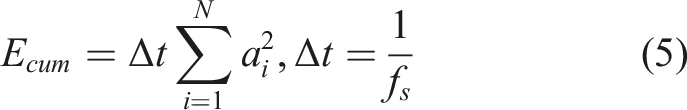
In addition to displacement data, the acceleration response of the system was also recorded, as presented in Figure 6. The acceleration analysis further supports the effectiveness of the metamaterial damper in reducing vibration levels along both the X and Y axes. These combined results validate the capability of the auxetic metamaterial structure to function as a compact and efficient passive damping solution for domestic applications. Acceleration result of high frequency running machine without damper (blue) and with damper (red); (a) full time testing evaluation result; (b) detail one second acceleration axes Y direction; (c) detail one acceleration axes X direction.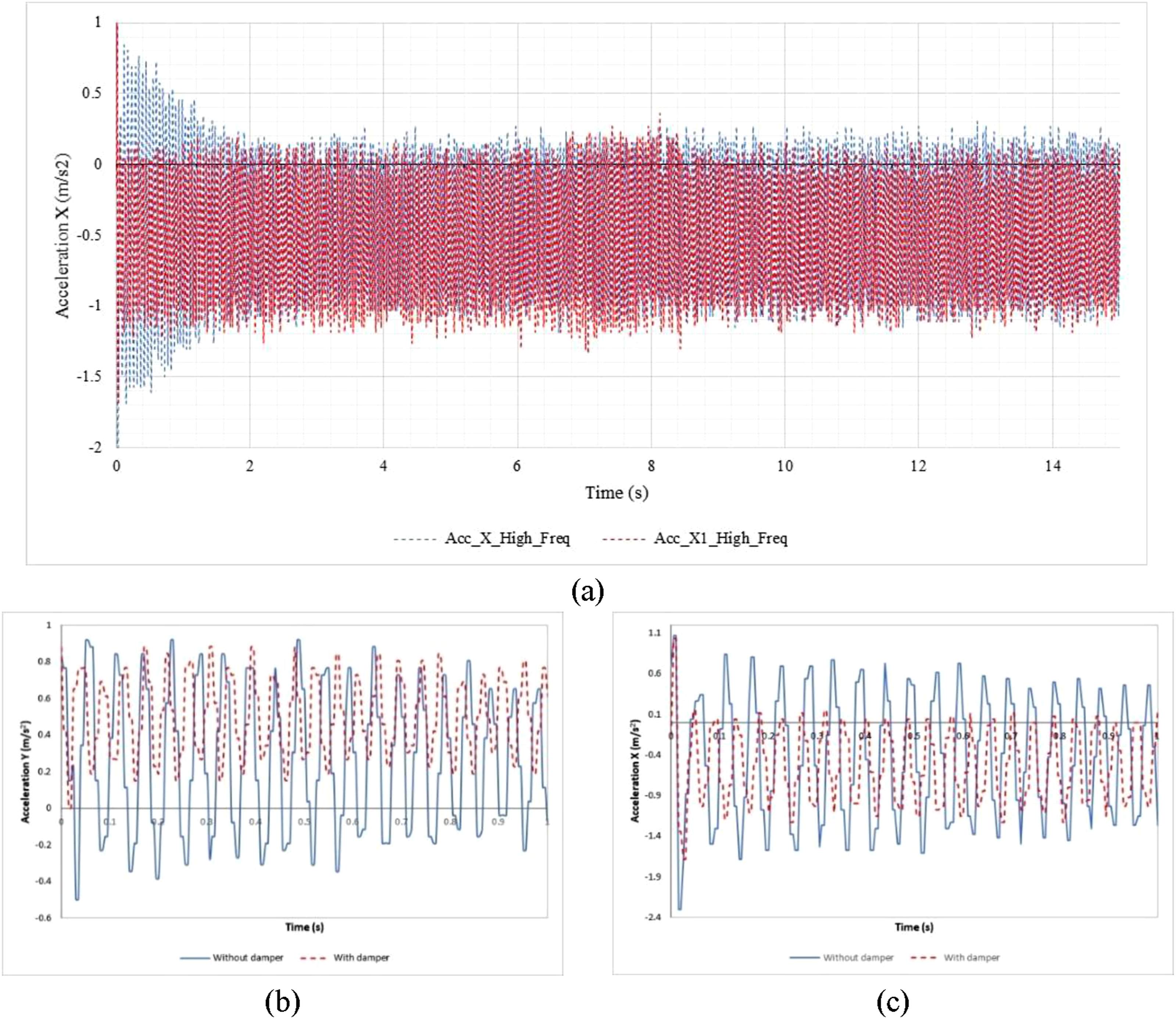
Based on the acceleration results shown in Figure 6, both the X-axis and Y-axis directions exhibit a noticeable reduction in acceleration values due to the implementation of the metamaterial-based damping system. Figure 6(a) presents the recorded acceleration along the X-axis during high-frequency operation over a 15-s testing interval. To provide a more detailed analysis, magnified views of the data are shown in Figures 6(b) and 6(c).
The experimental data clearly indicate that the addition of the auxetic damper significantly mitigates the initial impact or sudden jolt that typically occurs when the washing machine begins operating. In the Y-axis direction (Figure 6(b) ), for instance, the acceleration at start-up reached approximately 1.0 m/s2 without the damper installed. However, with the metamaterial damper in place, this value was reduced to around 0.5 m/s2, demonstrating a 50% reduction. A similar trend is observed in the X-axis direction (Figure 6(c) ), where both the initial and sustained acceleration values are substantially decreased, also by more than 50%, when the damping device is employed.
Although the damping device performs effectively under high-frequency conditions, the performance under low-frequency operation is comparatively less consistent. This does not necessarily imply that the device fails to function as a damper, but rather that the low-frequency motion of the washing machine produces a more irregular vibration pattern that is inherently more difficult to attenuate using passive damping mechanisms. The data from the low-frequency tests, presented in Figure 7, show no significant or consistent reduction in acceleration values. Acceleration result of low frequency in X direction; (a) full time period result; (b) detail of running motor section; (c) detail of break time motor section.
The acceleration plot in Figure 6 corresponds to low-frequency excitation along the X-axis over a 20-s testing period. During this interval, the motor operates intermittently, alternating between clockwise and counterclockwise rotation every 2 to 3 seconds, with pauses in between. This bidirectional rotational behavior creates varying impact intensities during the reversal of motor direction, resulting in spikes or surges in acceleration, particularly noticeable in one rotational direction. These spikes, attributed to the abrupt change in motor direction, are also evident in the data, as shown in Figure 7.
Overall, the experimental observations suggest that the proposed auxetic metamaterial damper is effective at suppressing high-frequency vibrations and initial impact loads. However, further optimization may be needed to enhance its performance under low-frequency excitation conditions, particularly in systems with irregular or asymmetric dynamic loading patterns. Future design iterations may involve modifying the structural configuration or combining active and passive damping mechanisms to ensure broader frequency responsiveness and more consistent vibration mitigation across various operational scenarios.
Figure 7 illustrates the acceleration results under low-frequency operation. The data reveal an interesting phenomenon resulting from the alternating rotation direction of the motor, as previously described. In the high-frequency analysis shown in Figure 6 through 6, the auxetic metamaterial damper demonstrated effective mitigation of sudden impacts, particularly during the initial motor start-up. A similar behavior can be observed under low-frequency conditions, but with more variability and mixed results.
The low-frequency tests revealed two distinct behavioral patterns: in some instances, the damping device clearly reduced acceleration values, while in others, the reduction was negligible or absent. To better illustrate this duality, Figure 7(a) has been divided into two sections, represented as Figures 7(b) and 7(c). These subfigures display different time segments from the same dataset, offering a clearer interpretation of the damper’s performance across varying conditions.
Figure 7(b) shows a segment where the auxetic metamaterial damper appears to have little or no effect on reducing the acceleration. This suggests that in certain cycles possibly during irregular motion or less intense motor operation the damper’s structure does not sufficiently respond to the vibration characteristics. In contrast, Figure 7(c) highlights a segment in which the damper performs significantly better, with a notable reduction in acceleration between the system with and without the damping device installed. This contrast under low-frequency excitation indicates that the auxetic metamaterial damper, in its current configuration, is more effective for higher-frequency vibrations and for reducing initial impact or shock loads during motor start-up. However, it is less reliable in attenuating vibrations in lower-frequency, intermittent operations where the excitation forces are more inconsistent.
Therefore, while the auxetic damper shows promising results for specific dynamic conditions, it may require further refinement to be universally applicable across a broad frequency range. One potential improvement could involve designing an adjustable damping mechanism within the axial component, allowing the system to adapt its stiffness or geometry based on the frequency of operation. This could be achieved through configurable unit cell geometries, variable wall thickness, or even incorporating tunable materials that respond differently under varying loads. The current results affirm that the auxetic metamaterial-based damper is particularly well-suited for high-frequency applications and impact mitigation. However, future iterations should explore adaptive design features to enhance the damper’s performance across a wider range of vibrational frequencies, especially for household appliances like washing machines, which often operate under mixed dynamic conditions. In the next analysis, the analysis was carried out for the results of the washing machine test using a damping device. This was done to determine the characteristics of the results of the damping device in handling the vibrations that occurred. So that it can be used as a consideration for improving the damping device in future work.
Figure 8 shows the result of 3D Plot Vibration mapping which illustrates the relationship between time (X-axis), X-direction acceleration (Y-axis), and Y-direction acceleration (Z-axis). In general, this plot shows vibration behavior over a time span of about 24 seconds. The vibration data shows random fluctuations with a range of X-direction acceleration ranging from −2 to 1 m/s2, while the Y-direction acceleration is in the range of 0 to 0.9 m/s2. This visualization indicates dense and rapidly changing vibration characteristics, without a clear harmonic pattern, so it can be assumed that this phenomenon originates from a complex mechanical vibration source, such as an electric motor, pump, or structural interaction experiencing external excitation. From the graphic display, there is no significant change in vibration amplitude over time, indicating that the system is in a stable condition without any indication of resonance or major damage during the observation period. 3D plot of vibration for x and y axis.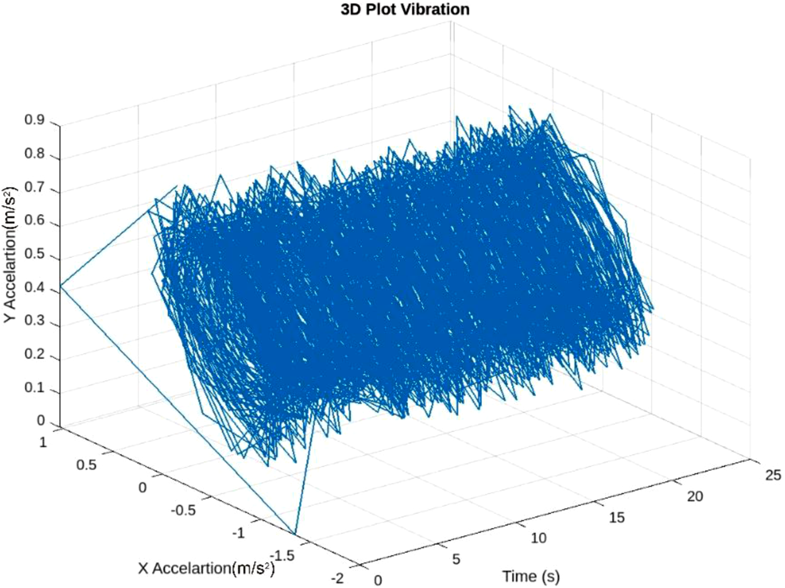
Figure 9 shows the acceleration versus time. The blue plot shows the raw acceleration signal fluctuating rapidly and densely around a mean value close to zero, with an amplitude between −2 and 2 m/s2. Above the acceleration graph, there are red circles indicating the acceleration peaks detected, centered around the value of 1 m/s2. The acceleration peak detection shows consistency in the maximum amplitude value, which is relatively stable throughout the measurement period. This indicates that the system is in normal operating conditions without any extreme acceleration spikes, which are usually signs of anomalies or damage. Peak acceleration detection.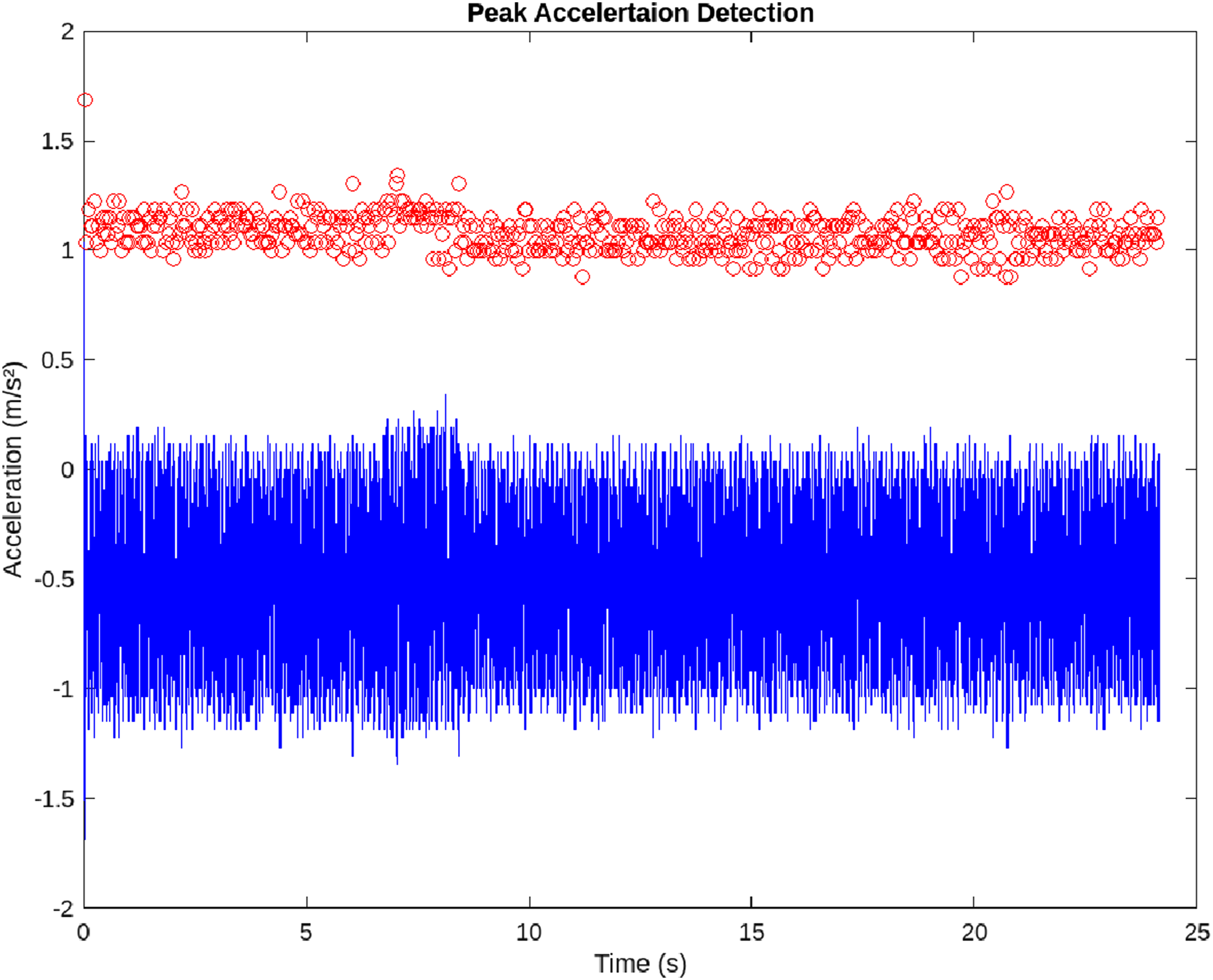
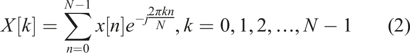
Based on the vibration pattern seen in the graph, it can be assumed that the acceleration signal contains high frequency components. To identify further, Fourier transform analysis (Fast Fourier Transform or FFT) can be applied as shown in Figure 10. By using FFT, the frequency spectrum of the acceleration signal will be visible, so that the dominant frequency that dominates the system vibration can be identified. If the dominant frequency is in the high range (for example above 100 Hz), this is in accordance with the indication of fast vibration recorded on the graph. Identification of the dominant frequency is important to understand whether the vibration source comes from structural resonance, mechanical imbalance, or other external factors. Frequency spectrum comparison x and y axis.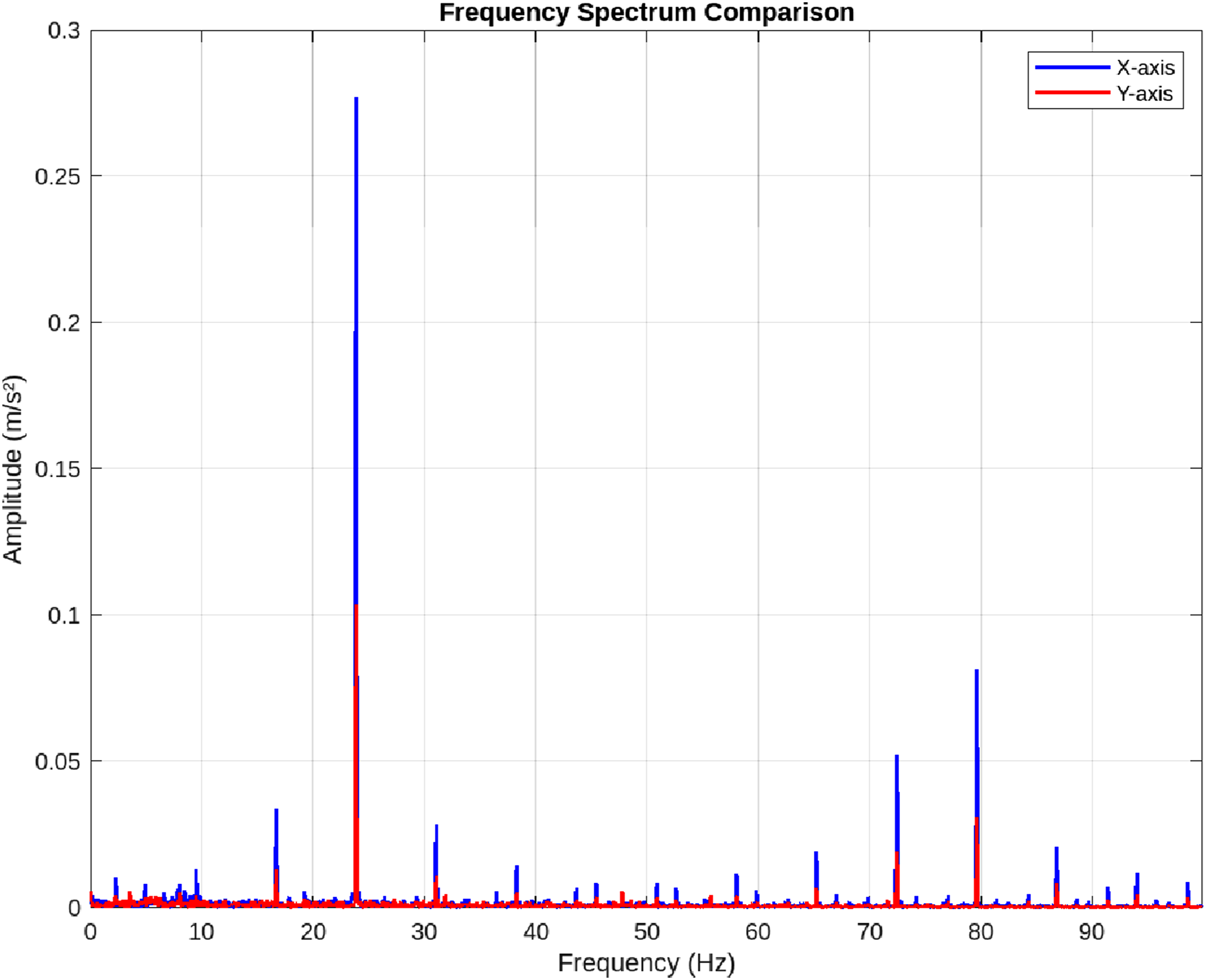
Regarding anomaly detection based on peaks, the peak distribution shown in the graph shows a relatively homogeneous distribution with amplitudes that are not much different. Under normal conditions, acceleration peaks will gather around one characteristic value. However, if an anomaly occurs in the system, such as component wear, bearing damage, or dynamic imbalance, sporadic peak spikes will appear outside the general pattern, either in the form of a significant increase in peak values or changes in the frequency of peak occurrence. In general, from the results of this graph, it can be concluded that during the observation period, no indication of major anomalies was found, but long-term monitoring is still needed to maintain system reliability.
Based on Figure 10, the frequency spectrum displayed shows that the vibrations on the X and Y axes have a dominant amplitude peak at a frequency of around 22 Hz. This peak indicates that the majority of vibration energy is concentrated at that frequency, both for the X and Y directions, although the amplitude on the X axis looks larger than the Y axis. In addition, there are several secondary peaks at higher frequencies, such as around 40 Hz, 70 Hz, and 80 Hz, but the amplitude is much smaller than the main peak at 22 Hz. This phenomenon indicates that the system experiences harmonic vibrations, where the main frequency dominates the dynamic response of the system, while the other frequencies are harmonics or small noise from the system.
The presence of frequency dominance around 22 Hz is important to note in dynamic analysis, because if the external excitation frequency approaches this frequency, resonance can occur which causes excessive vibration to increase. Therefore, these results can be used as a basis for the design of vibration damping systems or machine operation settings to avoid working at these critical frequencies. The comparison between the X and Y axes also indicates that the vibration in the X direction is stronger than in the Y direction, which may indicate an imbalance or non-uniformity of force distribution in the tested structure. Overall, this spectrum provides a clear picture of the vibration frequency characteristics of the system and is an important first step in structural health evaluation or dynamic performance optimization.
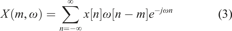
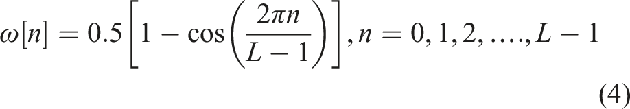
Figure 11 shows the results of the Short-Time Fourier Transform (STFT) analysis of the signal on the Y and X axes. The STFT visualization shows the relationship between time, frequency, and signal amplitude in the form of a three-dimensional graph. The horizontal axis represents time (seconds), the backward horizontal axis shows frequency (Hz), while the vertical axis shows the amplitude value in relative units. Short-time fourier transform (STFT) (a) y-axis; (b) x-axis.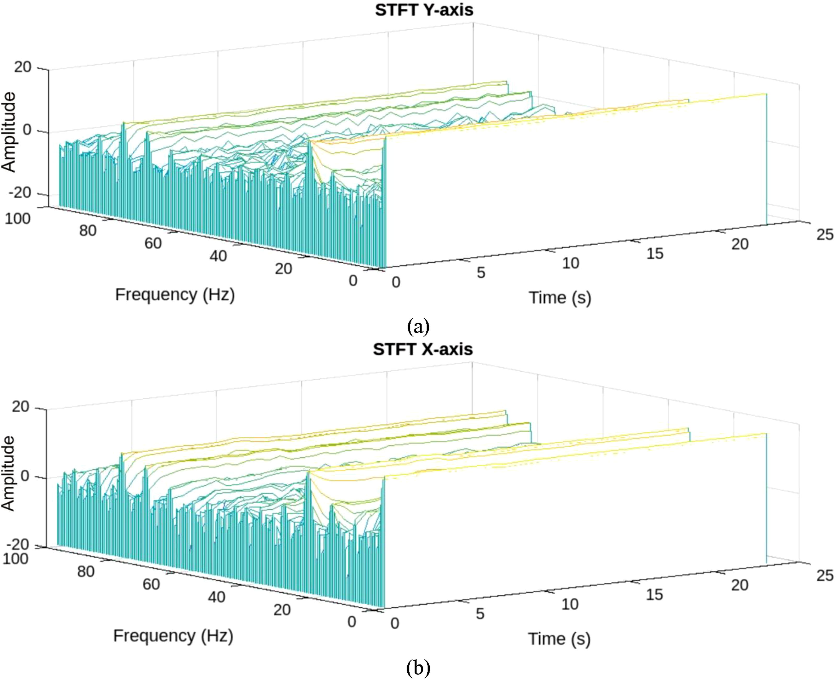
Based on the results in Figure 11(a) (Y-axis STFT) and 11b (X-axis STFT), it can be observed that the signal energy is concentrated at low frequencies, especially below 20 Hz. This frequency component shows amplitude stability throughout the observation duration, indicating the presence of a dominant and consistent periodic dynamic component in the signal. In addition, there are several harmonic components that appear at medium to high frequencies (40–100 Hz), although the amplitude is much lower compared to the low-frequency components. This phenomenon indicates that the signal contains noise or higher frequency variations, but its contribution is relatively small to the total energy.
On the Y axis, the amplitude fluctuations at low frequencies appear larger compared to the X axis, indicating that the movement or vibration on the Y axis is more dynamic. This difference can be caused by the dominant direction of the force or vibration acting on the system, or by the natural characteristics of the structure being tested. While on the X-axis, the amplitude distribution is smoother and more regular, indicating a more stable or damped vibration character. Overall, the STFT results show that the analyzed system has strong vibration characteristics at low frequencies with good time stability, and little contribution from high-frequency components. This information is important for understanding the dynamic behavior of the system, detecting anomalies, and directing the design of more effective controls or dampers.
Figure 12 shows a graph of vibration energy accumulation on the X-axis expressed in the form of cumulative RMS (Root Mean Square) against time. It can be seen that the cumulative RMS value at the beginning of the measurement is quite high, reaching more than 1.2, indicating that there is a large vibration energy at the beginning. However, over time, the cumulative RMS value decreases sharply and then gradually flattens, until it stabilizes at a value of around 0.65. This phenomenon indicates that most of the vibration energy is accumulated in the early phase of the measurement, and after that, the additional energy from the vibration becomes relatively small so that the cumulative RMS graph becomes flat. This decrease reflects that the system experiences a transient phenomenon at the beginning, where there is a surge of energy due to changes in conditions or initial excitation. After this transient, the system reaches a steady-state state where its vibration characteristics become stable. This graph is important in vibration analysis because it provides an illustration that the largest energy accumulation occurs at the beginning, and rapid stabilization indicates that the system has fairly good damping or dynamic control. In the context of vibration control or structural health monitoring, these results can be used to evaluate how quickly the system can achieve stability after experiencing a disturbance. Energy accumulation (x-axis).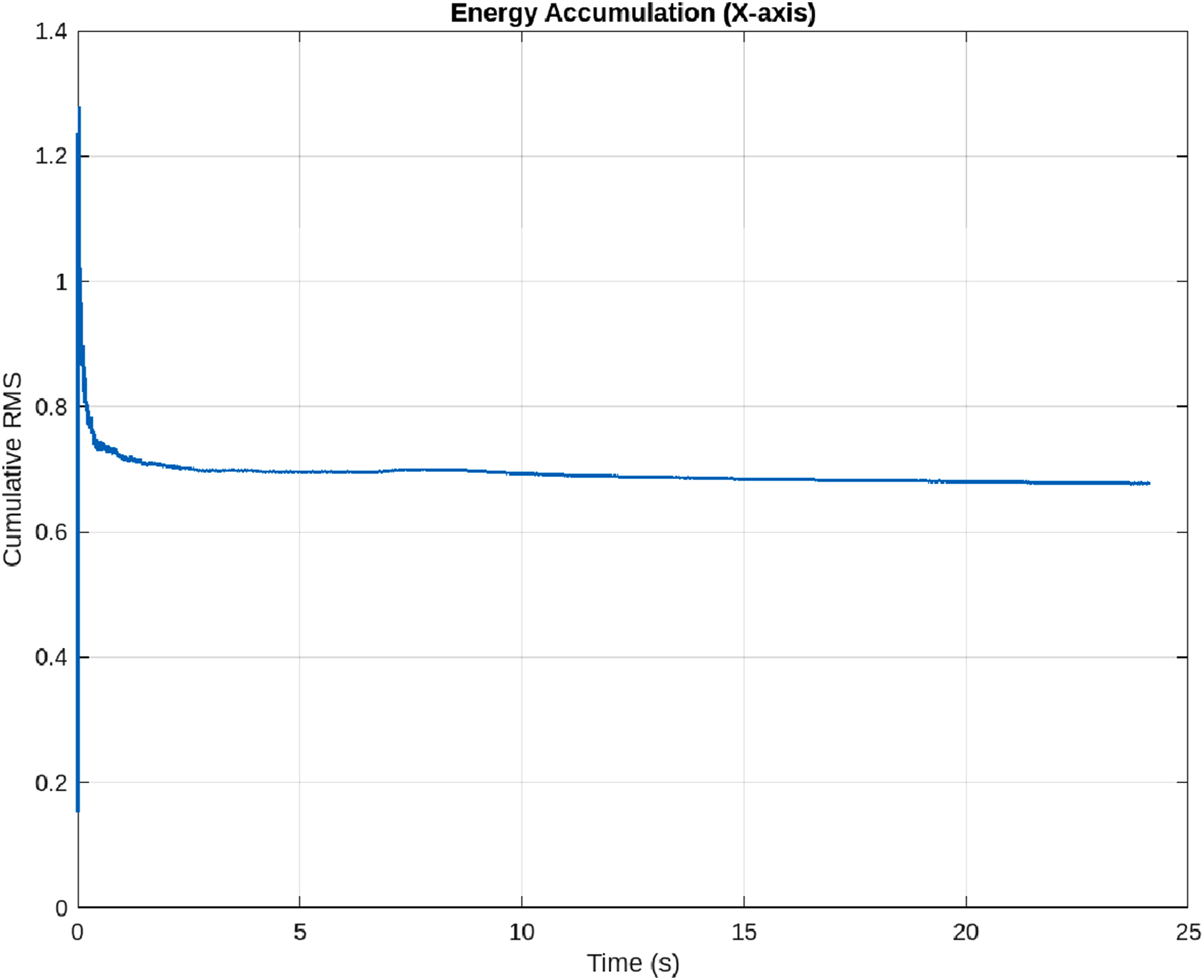
Figure 13 shows a scatter plot between the X-axis acceleration (X Acceleration) and the Y-axis acceleration (Y Acceleration) in m/s2. This scatter plot illustrates the spatial relationship between the two acceleration components in the system being observed. In general, the data distribution shows a scattered pattern with a tendency to form a dense area around the X acceleration value between −1.5 m/s2 to 0 m/s2, and the Y acceleration between 0.2 m/s2 to 0.8 m/s2. This indicates that most of the activity or vibration occurs in that range. The greater concentration of points in the negative region of the X acceleration indicates the dominance of the direction of motion or vibration towards the negative side of the X axis. Scatter plot x-axis versus y-axis.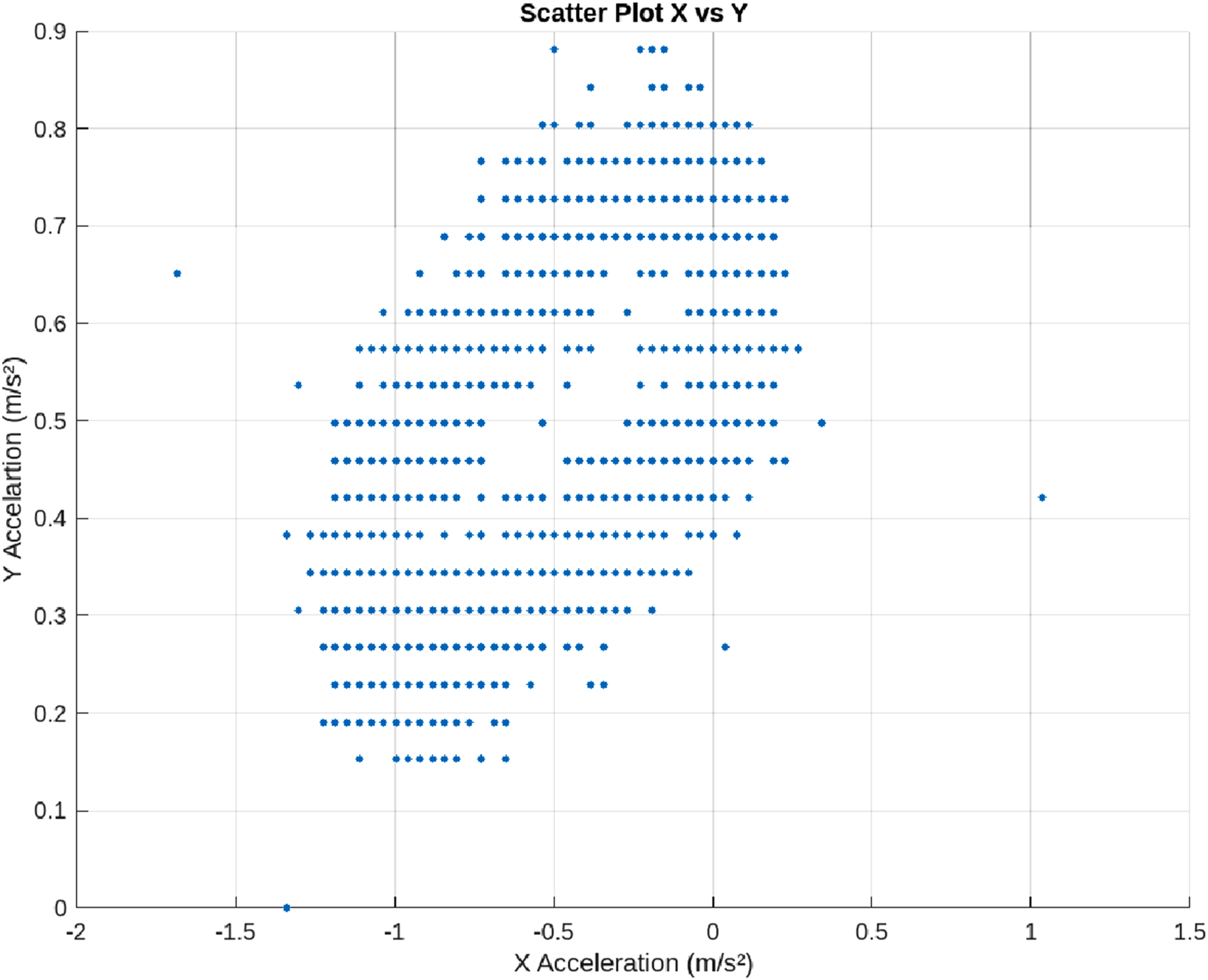
There is no strong linear correlation between the X and Y axis accelerations, as seen from the relatively widespread distribution of points without a particular straight line pattern. However, the inverted cone-shaped distribution pattern can be concluded that when the X acceleration value is increasingly negative, the variation in the Y acceleration becomes more limited. Conversely, when the X acceleration value approaches zero, the variation in the Y acceleration value becomes wider. This phenomenon may indicate the presence of a control mechanism or vibration limitation at certain conditions of the system, or differences in dynamic response between the two axes. In addition, there are several outliers in the upper right part of the plot, where the positive X acceleration values are close to 1 m/s2, which are relatively few in number. These outliers need to be further analyzed because they may indicate unusual events such as shocks, instability, or noise in the data. Overall, this scatter plot provides an important picture of the simultaneous distribution of accelerations on the two axes, helping to understand the dynamic characteristics of the system and identify potential dominant directions and anomalies during operation.
The acceleration distribution in the scatter plot provides insight into the dynamic behavior of the test system, such as a mechanical component or structure experiencing vibration. The distribution pattern that tends to be denser in the negative X acceleration range indicates a stronger force or motion direction dominance towards the negative X axis. This can be interpreted as a result of repeated excitation forces, moments of inertia, or even imbalance in the vibration source that is more dominant in one direction. Meanwhile, the acceleration value on the Y axis has a fairly consistent variation range and does not show a significant shift towards the X value. This indicates that the system has a more controlled or symmetrical response in the Y direction. A larger spread at X values approaching zero can indicate a more complex directional transition or oscillation.
The results of this scatter plot provide an important basis for decision making for vibration control strategies. The dominance of vibration amplitude in the negative X direction indicates that the damper or vibration isolation system can be focused on that direction. For example, the placement of absorbing materials or the tuning of active control parameters is better directed to dampen the dominant vibrations on the X axis. In addition, irregular distributions at certain values may indicate the need to examine the source of disturbances or unwanted vibrations (misalignment, unbalance, or resonance effects). Observation of outliers also provides an indication of momentary shocks or sudden disturbances, which can be compensated for by protection systems or real-time monitoring. Overall, this visualization is useful as input in the design and validation of data-driven vibration control systems, including the application of passive and active controls for dynamic system stabilization.
Validation was performed by performing a simulation process that was set up close to the original conditions. The data used for validation was natural frequency data obtained from the frequency spectrum results compared with the analysis modal in the simulation. The simulation results, which displayed 6 natural frequency modes, showed a match with the natural frequencies in the experimental test. The comparison graph between simulation and experiment is shown in Figure 14 below. The figure shows that the largest error between the experimental data and the simulation has a difference of 5 Hz where the experimental data in the first model is 22 Hz, while the first mode in the simulation is 27 Hz. However, the data in the next mode shows a more precise match with an error below 3% with a difference of only 1 to 2 Hz. Validation of research results with simulations on 5 natural frequency modes of the system.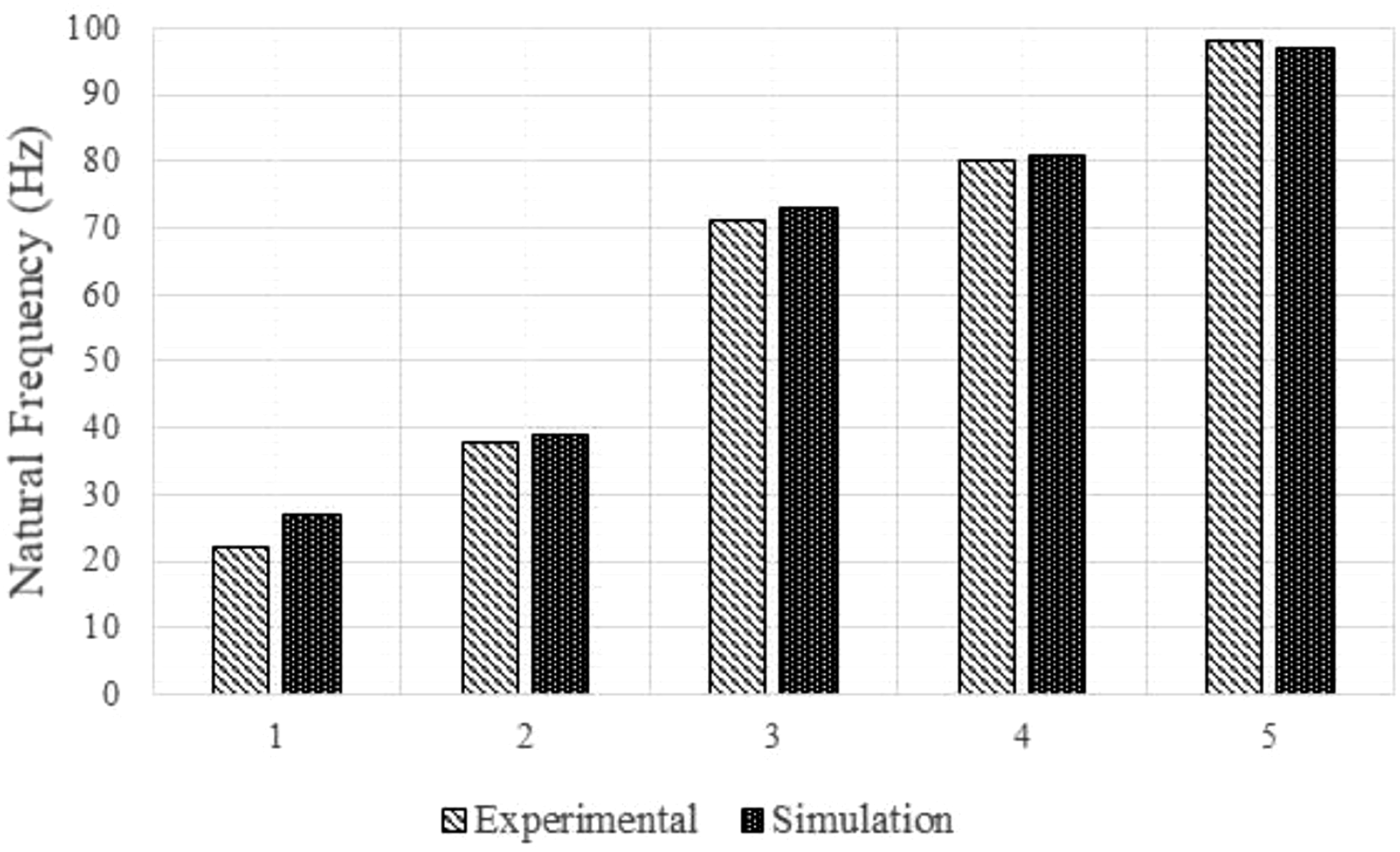
Conclusion
Based on the analysis and discussion that has been done on the comparison of test results without damping and with damping, the installed vibration pads device has been able to reduce vibrations that occur in the performance of the washing machine. There are two types of frequencies used, the first is high frequency and the other is low frequency. The results of the high frequency test are quite significant in reducing the acceleration value, which is approximately 50% on both the X and Y axes. While in the displacement value shown previously, the reduction in displacement occurs at the beginning of the machine running is around 28%, and the reduction at a certain time interval shows a fairly high value of 60%. However, the low frequency test did not show significant results. In other words, the installed vibration pads device is a device that is suitable for use at high frequencies. This requires design adjustments to obtain a wider frequency bandwidth. Then the analysis carried out specifically on the work of the machine with the addition of vibration pads has been reviewed on the X and Y axes. The test results show a tendency for uniform values that based on the detection of peak values, the peak distribution that appears on the graph shows a relatively homogeneous distribution with amplitudes that are not much different. This indicates that there is no anomaly. There is no spike in the peak value which can be assumed that there is no dynamic imbalance, component wear or bearing damage. The STFT results also strengthen these findings by showing a consistent frequency spectrum distribution over a certain time span, which describes the stability or repetition of the vibration pattern. These findings are very important in the development of vibration control strategies, where focus can be directed at the dominant axis and frequency to improve the overall system stability. In addition, this information can be utilized in optimizing the design of structures or damping systems to be more responsive to the actual vibration characteristics that occur. However, this study still has limitations in several areas. These limitations can be used as material for further research, such as mathematical models on auxetic damping devices that can be used as future research and validation of this model. Explicit dynamic simulations are also needed to demonstrate the complete system phenomena. Based on the phenomena that emerged from the results of this study, the potential for significant changes in design geometry can have a good damping impact. The relationship between metamaterials as a whole also needs to be studied more fully starting from the fundamental concept. The design used in this study is a fairly complex design intended to address multi-degrees of freedom. Therefore, fundamental research on at least one or two degrees of freedom systems is necessary. Ultimately, the results of this study contribute to the application of good real damping within a certain period (the research period). The durability aspect is also worth considering by conducting appropriate testing.
Footnotes
Acknowledgments
The authors would like to thank the Universitas Jenderal Soedirman for the financial support provided through the Riset Dasar Unsoed 2026, with contract number 13.318/UN23.34/PT.01.00/IV/2026.
Declaration of conflicting interests
The authors declared no potential conflicts of interest with respect to the research, authorship, and/or publication of this article.
Funding
The authors declared the following potential conflicts of interest with respect to the research, authorship, and/or publication of this article: This research was funded by Universitas Jenderal Soedirman under the funding scheme of Riset Dasar Unsoed 2026 with contract number 13.318/UN23.34/PT.01.00/IV/2026.