
Abstract
The solar chimney power plants produce electricity and thermal heat using the solar radiation. The thermal study of the solar chimney power plants is required since these systems are characterized by their high costs. This paper focuses on the study of a solar chimney power plant coupled with a turbine to increase the generated power. Thus, four turbine diameters are proposed. For each configuration, the distribution of the magnitude velocity, the air temperature, and the pressure was discussed. The results indicate that the generated power increases with the increase of the turbine diameter. This technical solution is identified interesting for designers to increase the generated power.
Introduction
The solar chimney power plants (SCPPs) are designed to produce electrical energy from the solar radiation. A SCPP is equipped usually by one or many turbines which are designed to extract the kinetic energy of the wind flowing upward due to the natural convection. Then, the generator, which is coupled with the turbine, converts the wind’s kinetic energy into electricity. Several papers reported that the use of the SCPP is a promising solution to produce electricity. The optimization of the solar setup needs the study of the geometrical parameters such as the collector roof height, 1 the collector diameter, the chimney height, 2 the chimney diameter, the inclination of the roof, 3 and the design of the turbine. The first prototype of the SCPP was constructed in Manzanares. The prototype is characterized by a height equal to 194.6 m and a collector radius equal to 122 m. In this context, Haaf et al.4,5 developed the results of preliminary tests of the SCPP. The authors presented the energy audits, the collector efficiency values, the pressure losses due to friction, and the losses in the turbine section. Ayadi et al. 3 presented a numerical model to assess the performance of the solar chimney power systems while varying the collector roof angle. The authors noted that the efficiency of the SCPP increases with a negative angle of the collector roof. Xu et al. 6 examined numerically the impact of the solar radiation and the pressure drop across the turbine on the generated power of the SCPP. From the literature, researchers have reported some configurations of the turbine layouts such as the single rotor turbine without inlet guide vanes (IGVs), single rotor turbine with IGVs, counterrotating turbine without IGVs, and counter rotating turbine with IGVs. The turbo-generator of the Manzanares prototype was designed by Schwarz and Knauss. 7 The authors proposed a single rotor layout without guide vanes. Later, Gannon and Von Backström 8 carried out an experimental analysis of the solar chimney turbine performance. It was reported by the authors that the total-to-total efficiency and the total-to-static efficiency are equal, respectively, to 85–90 and 77–80% over the concept range. Another work was reported by the same authors 9 to develop analytical equations to defining the impact of each coefficient on the efficiency on the turbine. Recently, Ming et al. 10 carried out a numerical simulation for a SCPP coupled with a five-blade turbine. The system is characterized by the chimney height equal to 400 m, the chimney radius equal to 30 m, and the collector radius equal to 1500 m. The authors presented the impact of the rotational speed of the turbine on the average velocity of the chimney outlet, the average temperature of the chimney outlet, the pressure drop across the turbine, and the mass flow rate of the system. The maximum generated power and the turbine efficiency are about 10 MW and 50%, respectively. Guo et al. 11 presented a 3D numerical simulation of a solar chimney coupling with a turbine. In their work, they varied the rotational speed of the turbine to study the optimal operating condition of the turbine. In their study, they have taken account of the impact of the incident angle of the sunlight. The results revealed that the hourly variation of the zenith angle is an important parameter to forecast the annual performance of the SCPP.
Focusing on the literature, it has been noted that the most published papers highlight the effect of the geometrical parameters of the solar setup such as the collector roof height, the collector diameter, the chimney height, and the chimney diameter. In this paper, we are going to focus on the study of the turbine design. Especially, the effect of the turbine diameter on the air flow characteristics inside a SCPP is reported. This paper shows that the turbine diameter is an important parameter to increase the generated power of an existing SCPP. Otherwise, the increase of the turbine diameter could increase the generated power of a solar setup.
Experimental setup
A prototype of a SCPP was constructed in the National School of Engineers of Sfax at University of Sfax. Sfax is located in the South East of Tunisia, North Africa. Tunisia has been identified as a case study to quantify the amount of the solar energy available locally and its distribution across the country. 12 The experimental setup, depicted in Figure 1, is characterized by the latitude equal to ϕ = 34.726°N and the longitude equal to L = 10.717°E. The prototype is mainly composed of a collector, a chimney, an absorber, and a turbine which is coupled by a generator to produce electricity. The collector diameter is equal to D = 2750 mm, the collector roof height is equal to h = 50 mm, the chimney height is equal to H = 3000 mm, and the turbine diameter is equal to dt=150 mm. The collector is a transparent membrane which covers the ground. It is made by a strong transparent polymer. This plastic cover has a high thermal characteristic and a resistance to breakage. However, the chimney is a polyvinyl chloride pipe. The wood is chosen to construct the external surface of the absorber, due to commercial availability and economic reasons. Experimental data are based on the measurements of the air temperature and the air velocity within the solar system. In order to record the evolution of the temperature over the time, a data acquisition has been used. This card is programmed to save periodically the air temperature each 1 h. The measurement locations are arranged along the collector radius. The card is connected by 11 thermocouples type J. However, the values of the air velocity are recoded using a wire anemometer within the collector.
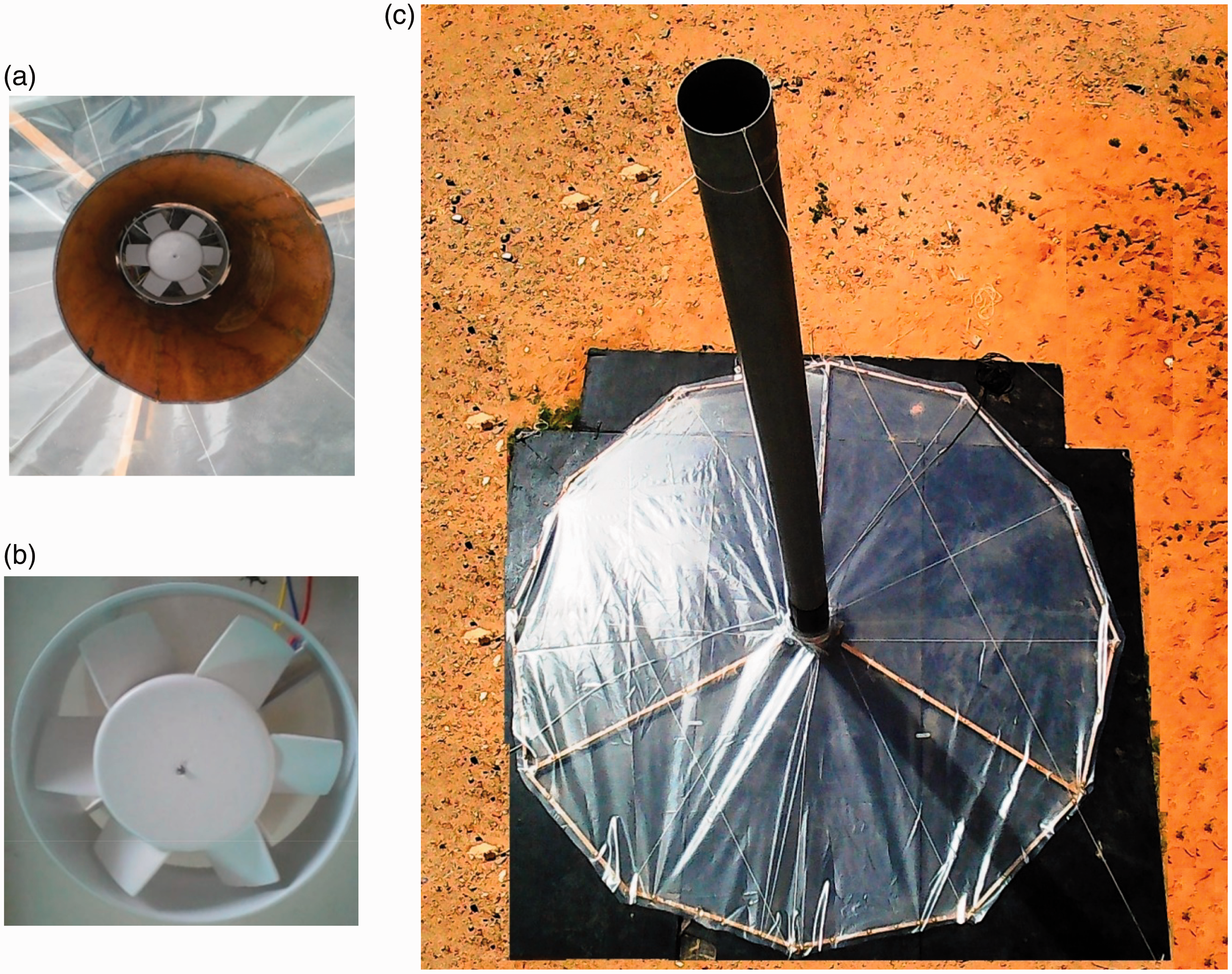
The experimental setup of the SCPP. (a) Top view of the system, (b) the turbine, and (c) the experimental prototype.
Numerical method
Mathematical formulation
The equations describing the air flow inside the SCPP were solved using the commercial CFD code ANSYS Fluent 17.0.13–15
The continuity equation is written as follows

where
The motion equations are written as follows


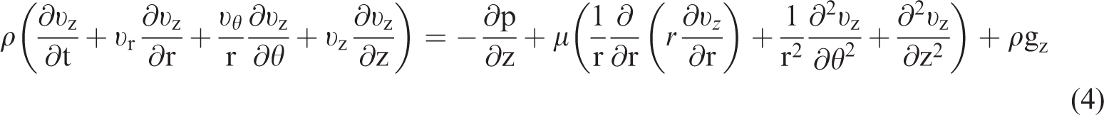
In this paper, we have used the multiple reference frame (MRF) model. 16 In fact, Fluent provides users the possibility to act out the flow in a rotating reference frame, where the acceleration of the coordinate system is comprised in the equation of motion. The air flow, surrounding the turbine region of the SCPP, can be simulated in a coordinate system that is moving with the rotating equipment. Therefore, it undergoes a constant acceleration in the radial direction. In the case of a rotating reference frame, the rotation boundaries become stationary with respect to the rotating system as they move at the same speed as the reference frame. The MRF model is used to simulate the interaction between the turbine and the chimney. Thus, when the equations of motion are solved in a rotating reference frame, the acceleration of the air flow is increased by supplementary terms which are integrated to the equations of momentum.
The maximum mechanical power produced by the turbine is given by the following formula17,18

The collector efficiency is expressed as the ratio of the specific rate of the heat outflow and the solar energy input.
19
The collector efficiency is written as follows

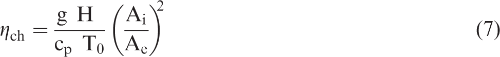
The chimney efficiency is given as follows
17
Boundary condition
Computational results are critically affected by the boundary conditions of the system. A 3D model was proposed for all the considered simulations. A standard atmospheric pressure and temperature conditions are imposed. The evolution of the ambient air temperature is presented in Figure 2. The collector inlet is specified as the pressure inlet and the chimney outlet is specified as the pressure outlet. In fact, the pressure inlet and the pressure outlet are equal to the atmospheric pressure defined by patm=101325 Pa. Indeed, the collector roof is considered as a semitransparent wall.
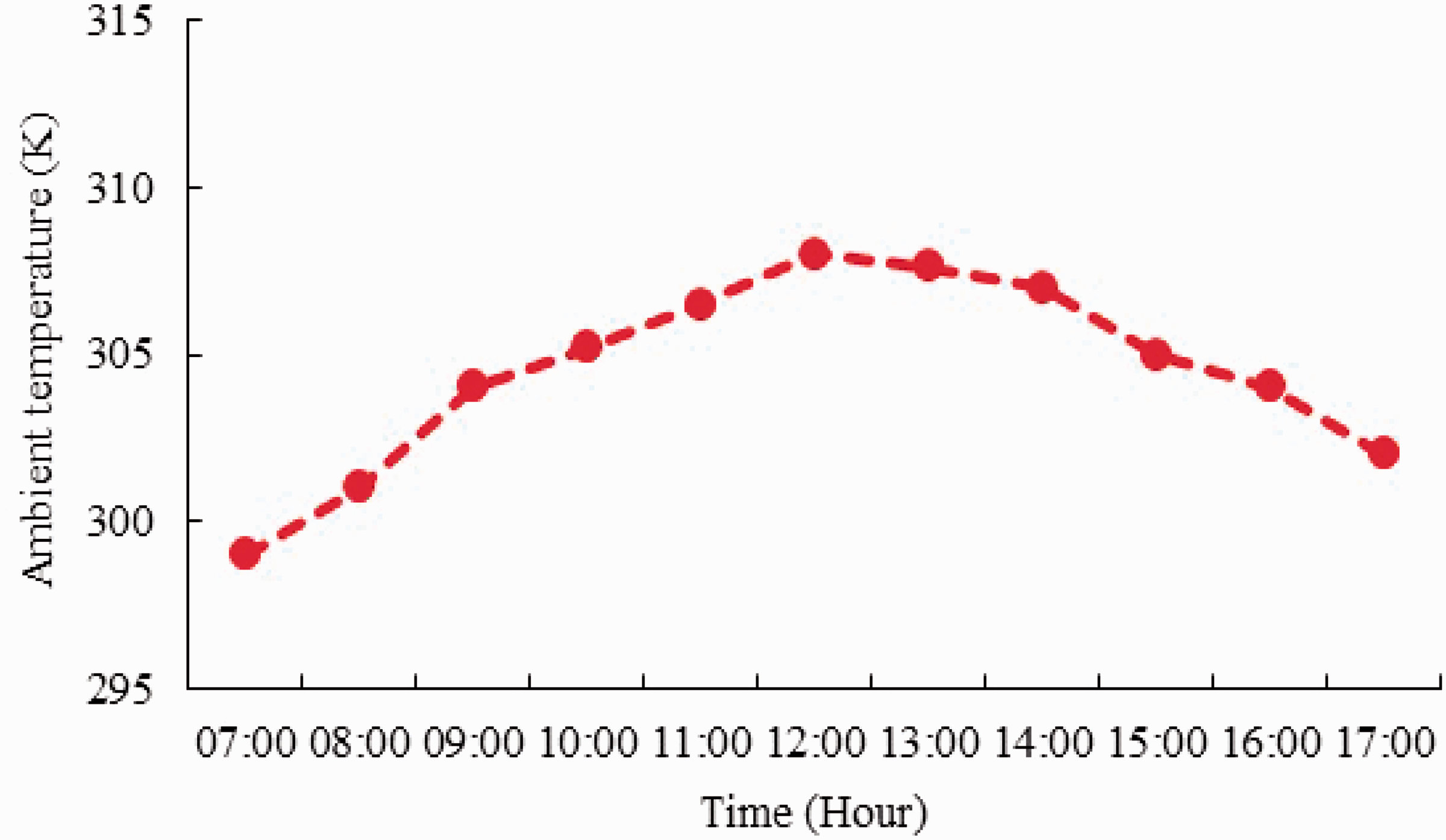
Ambient temperature.
Meshing
The establishment of efficient computational calculations requires the generation of different types of meshing. Otherwise, poor quality grid will cause inaccurate solutions and slow convergence. In fact, numerical results vary from one meshing to another. A meshing grid is generated using ANSYS-Meshing preprocessor. The appropriate choice of grid type depends on the geometric system and the number of nodes. In this context, many different meshing configurations are tested and a grid independence test was done to evaluate the optimum node sizes and elements. In order to reduce the amount of time spent on the generation of meshing, 20 840,000 nodes were used for all the numerical simulations since this meshing gives a good agreement compared with the experimental data as presented in Figure 3.
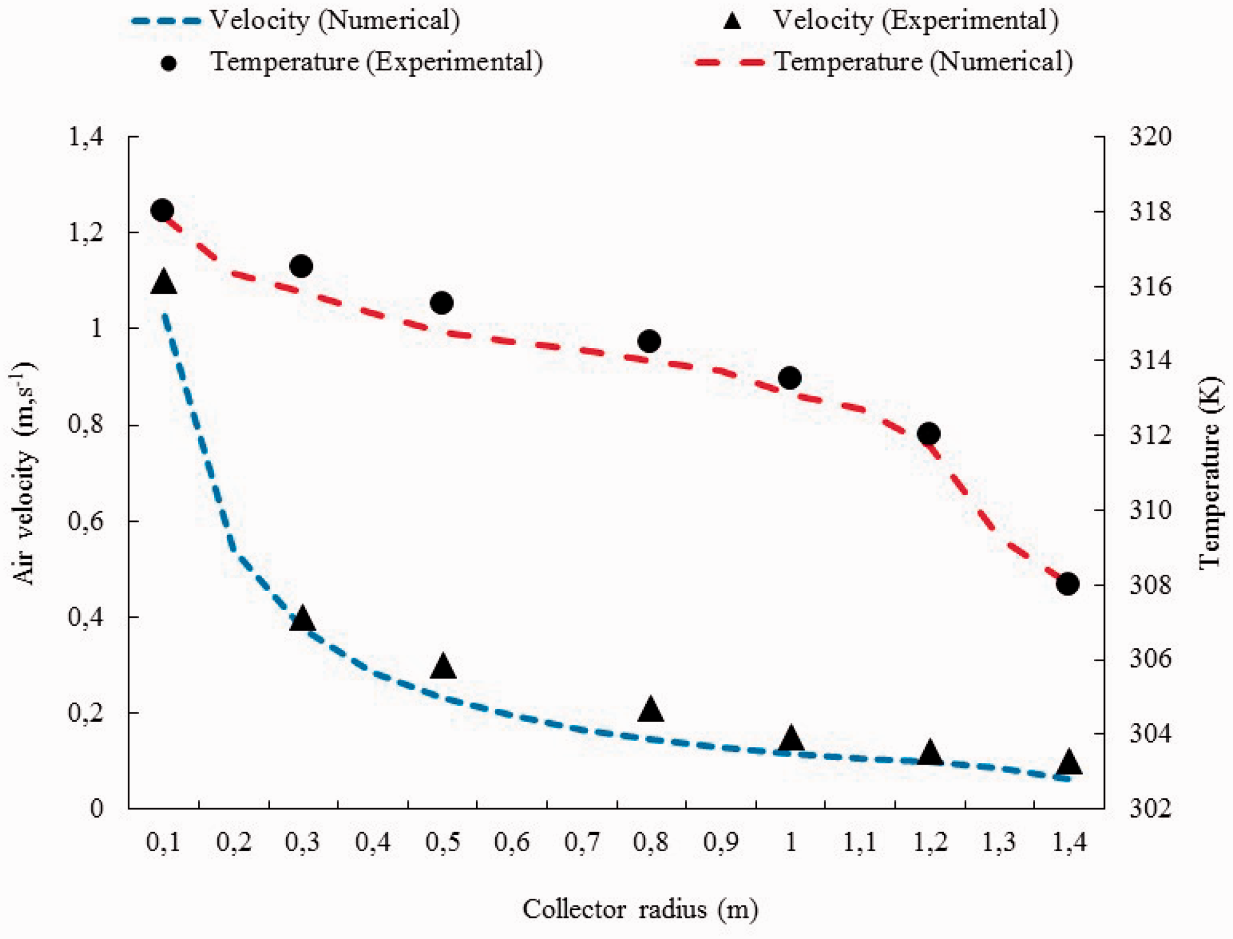
Validation of the numerical model.
Results and discussion
Four turbine diameters are proposed to highlight the effect of the turbine diameter on the local characteristics of the air flow within the SCPP. ANSYS Fluent 17.0 is used to simulate the air flow within the SCPP. Fluent has been used by several researchers.21,22 For each turbine diameter, the distribution of the magnitude velocity, the air temperature, and the pressure was presented and discussed in two different planes. As presented in Figure 4, the first plane is defined by z = 0 and the second plane is defined by θ = 0°.
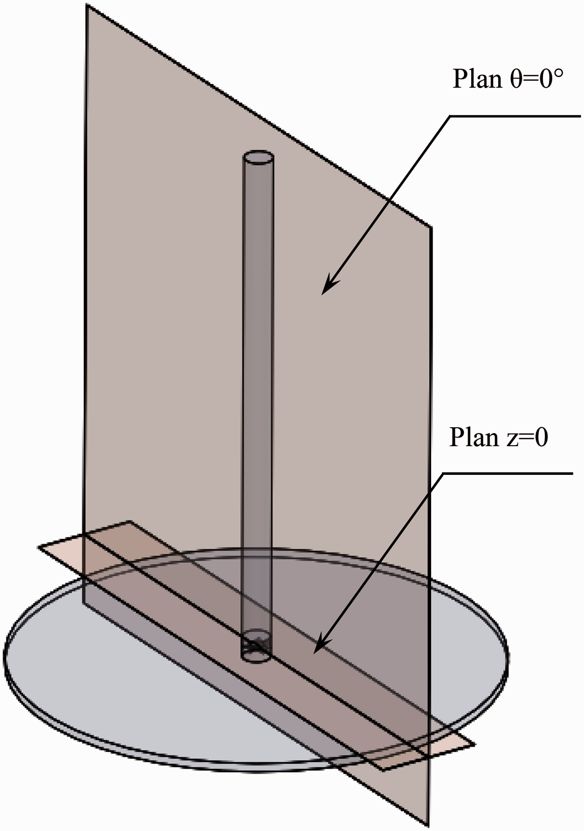
Modeling of the SCPP.
Air velocity
Figure 5 shows the distribution of the air velocity field on the plane defined by θ = 0° in the zone surrounding the rotating domain. From Figure 5, it has been noted that the air flow occurs from the collector inlet to the chimney section for all considered cases. In fact, the SCPPs use the natural buoyancy of the heated air flow to rotate the turbines. From one case to another, it has been noted a difference in the distribution of the back flow near the rotating wall. In fact, the reversing flow will affect the efficiency of the turbine. The comparison between these results shows that the increase of the turbine diameter promotes the air circulation at the chimney bottom.
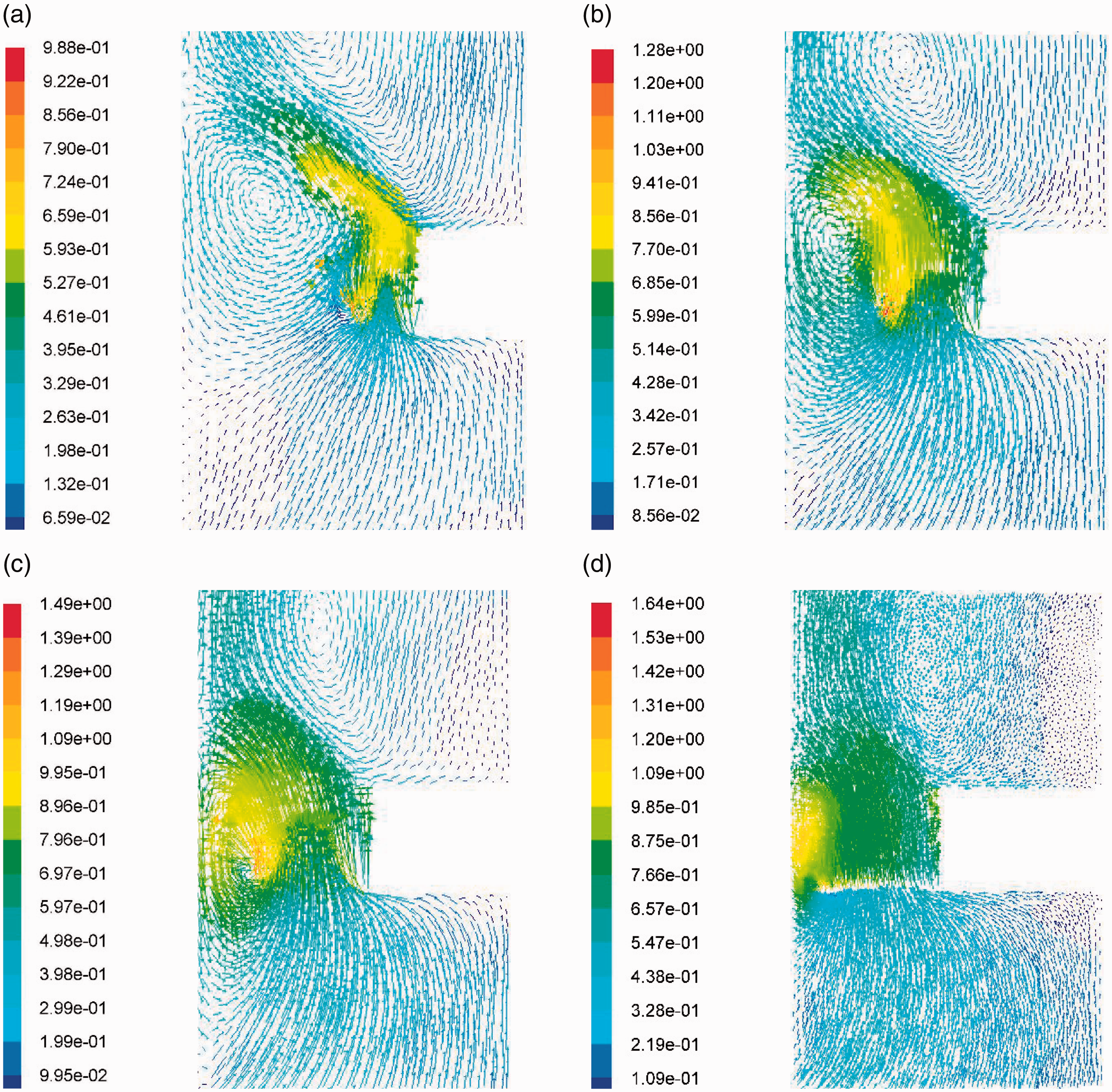
Distribution of the velocity field in the plane defined by θ = 0°. (a) dt=90 mm, (b) dt=120 mm, (c) dt=140 mm, and (d) dt=150 mm.
Figure 6 depicts the distribution of the air velocity field in the median plane of the turbine for the different considered turbines. While focusing on these results, it has been noted an increase in the air velocity in the zone surrounding the blades of the turbine for all considered cases. In fact, the increase of the blade radius causes an increase in the air velocity. This fact can be explained by the relation between the angular and the linear velocity. Comparing these results, computational results show that the magnitude air velocity depends on the turbine diameter. In fact, the maximum values of the air velocity are recorded for both the third and the fourth configurations. Otherwise, the magnitude velocity can be raised by 155% inside the chimney for a variation of turbine diameter Δdt=60 mm.
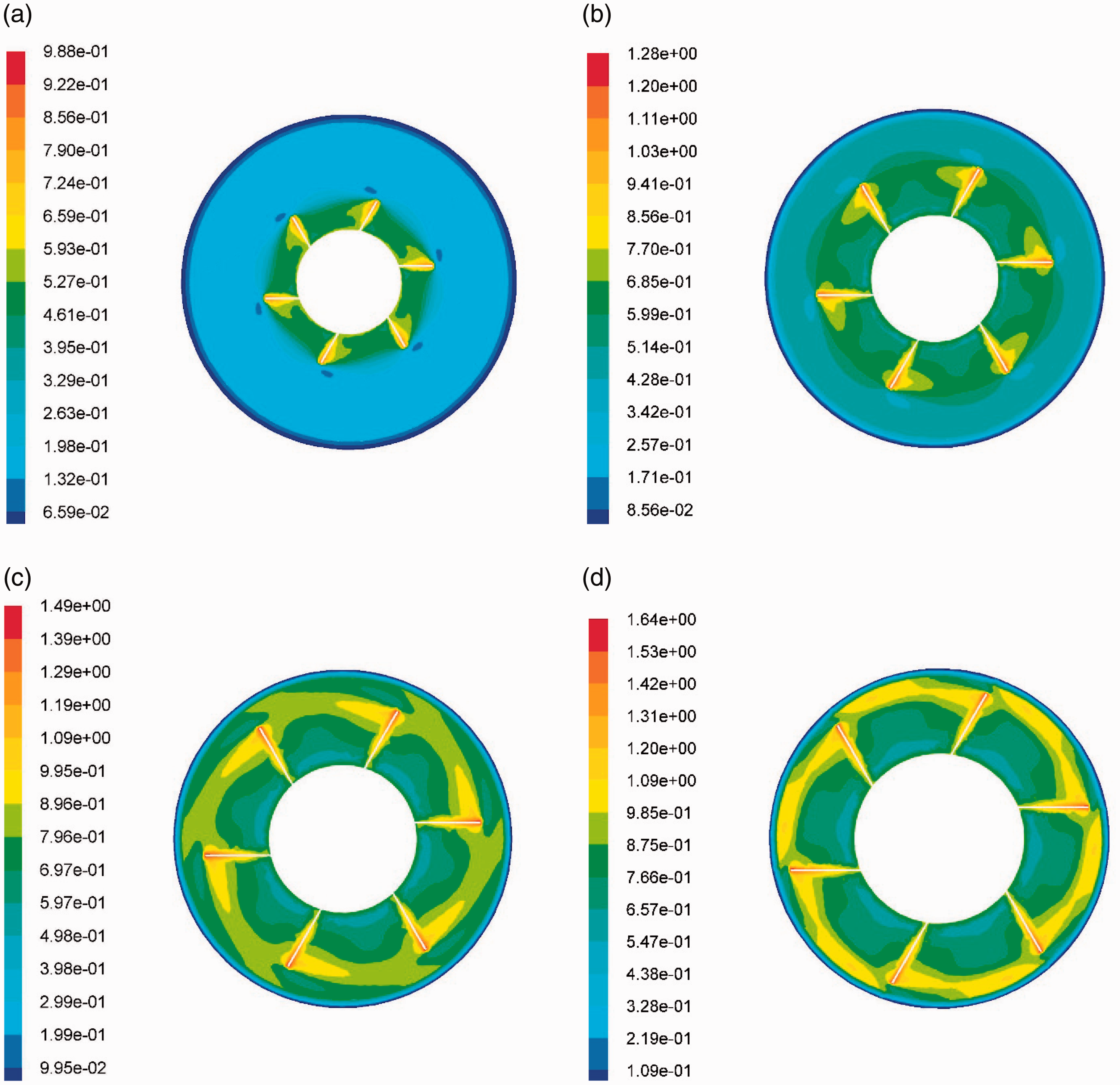
Distribution of the magnitude velocity in the plane z = 0. (a) dt=90 mm, (b) dt=120 mm, (c) dt=140 mm, and (d) dt=150 mm.
Air temperature
The distribution of the air temperature in the plane z = 0 m is depicted in Figure 7 for the different considered turbine diameters. From these illustrations, it has been noted a rapid increase of the air temperature near the absorber and the chimney axis. However, the air temperature decreases progressively away from the chimney axis. Indeed, it has been noted a decrease in the air temperature within the SCPP while increasing the value of the turbine diameter. In fact, the increase of the turbine diameter favors the cooling of the heated air at the bottom of the chimney. The comparison between these findings confirms that the turbine diameter affects the distribution of the air temperature within the SCPP.
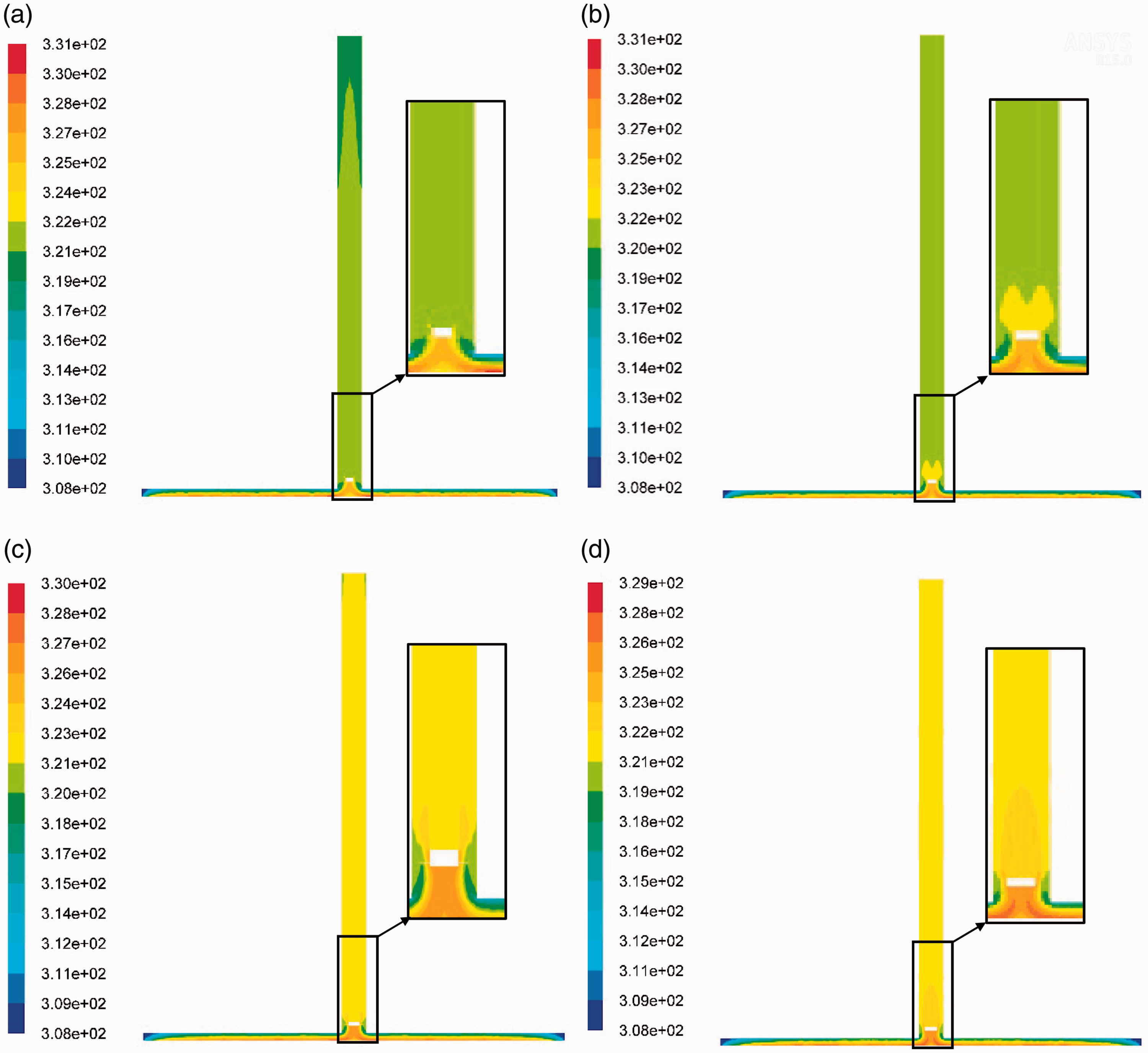
Distribution of the air temperature in the plane θ = 0°. (a) dt=90 mm, (b) dt=120 mm, (c) dt=140 mm, and (d) dt=150 mm.
Static pressure
The distribution of the static pressure in the plane defined by θ = 0° is shown in Figure 8 for the different considered configurations. While focusing on these illustrations, it has been noted a negligible variation of the static pressure under the collector roof. However, a brutal increase of the static pressure is recorded at the bottom of the chimney section. These results are confirmed by Figure 9 which depicts the distribution of the static pressure in the plane defined by z = 0. From Figure 9, depression and compression zones are noted. The depression zone is recorded in the inferior parts of the turbine at the tip of the blade. However, the compression zones were depicted in the superior parts of the turbine. From one configuration to another, it has been noted that the maximum value of the static pressure increases with the increase of the turbine diameter. The comparison between these results confirms that the turbine diameter presents an impact on the distribution of the static pressure inside the SCPP.
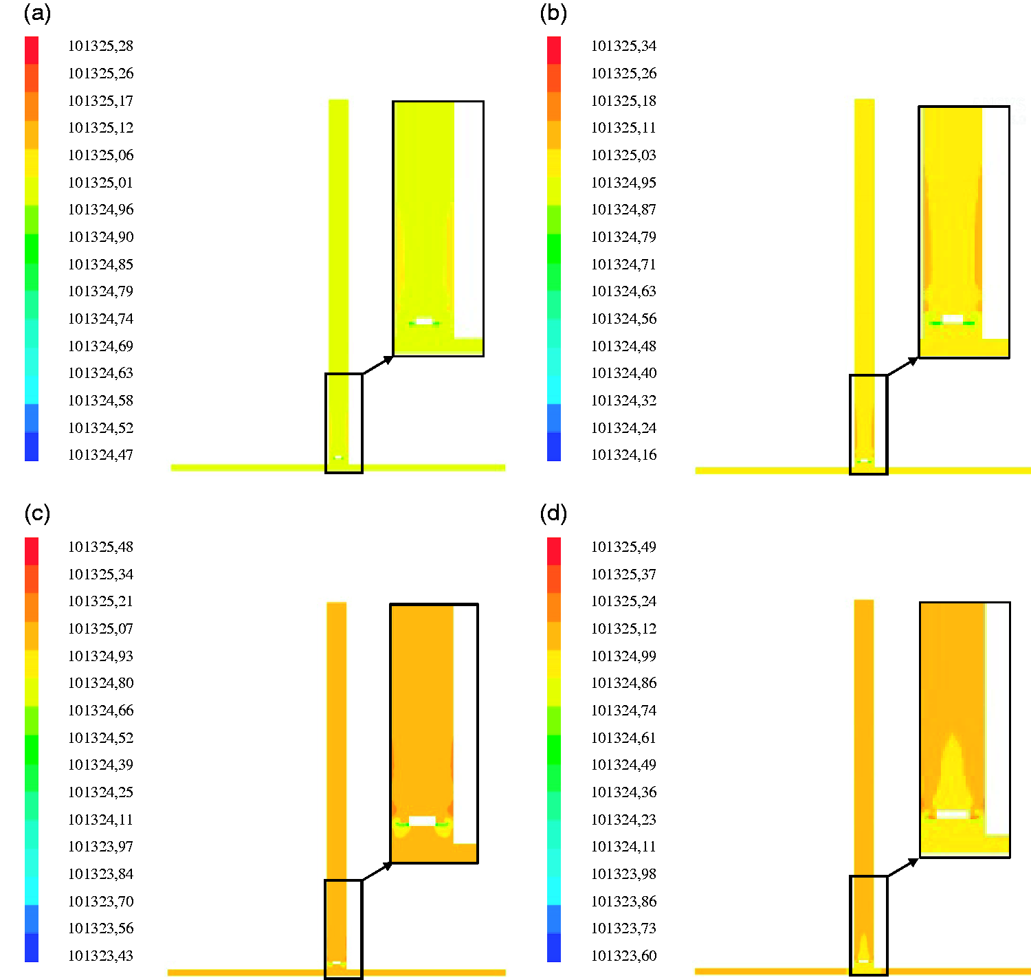
Distribution of the static pressure in the plane θ = 0°. (a) dt=90 mm, (b) dt=120 mm, (c) dt=140 mm, and (d) dt=150 mm.
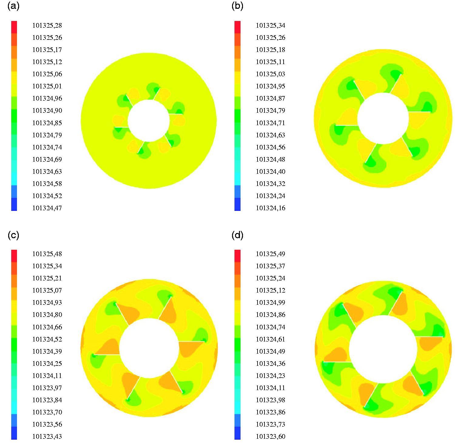
Distribution of the static pressure in the plane z = 0. (a) dt=90 mm, (b) dt=120 mm, (c) dt=140 mm, and (d) dt=150 mm.
Generated power
The knowledge of the local characteristics of the air flow is essential to assess the power output of the SCPP. Figure 10 presents a comparison between numerical and experimental findings of the generated power. Comparing numerical and experimental values, the coefficient of determination (R2) is equal to 0.89, the mean absolute bias error is equal to 0.0172, and the root mean square error is equal to 0.0174. According to Figure 10, it has been noted that the evolution of the generated power depends on the turbine diameter. In fact, the power output increases with the increase of the turbine diameter. Otherwise, the generated power could be raised by 155% for a turbine diameter variation equal to 60 mm. The comparison between these results confirms that the turbine diameter is an important parameter to enhance the power output.
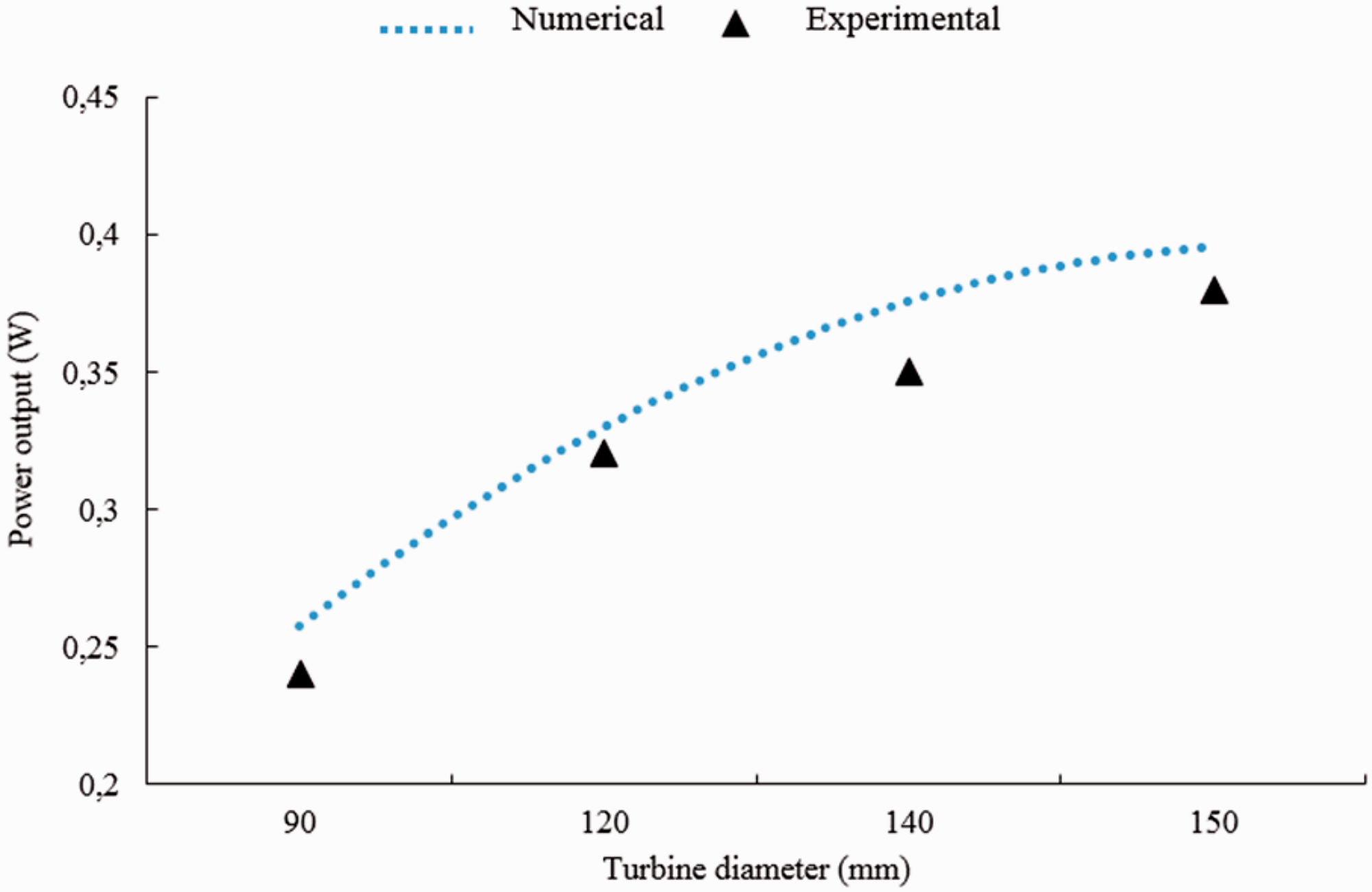
Generated power.
Conclusion
The purpose of this paper is to favor the circulation of the air flow within a SCPP. The diameter of the turbine is varied from dt=90 mm to dt=150 mm to highlight the effect of the turbine diameter on the local characteristics of the air flow within the SCPP. For each configuration, the distribution of the magnitude velocity, the air temperature, and the pressure was discussed. Indeed, it has been noted that the generated power increases with the increase of the turbine diameter. Otherwise, the power output can be raised by 155% for a variation of Δdt=60 mm. In fact, the generated power depends on the efficiency of the turbine rotor. This technical solution is identified interesting for designers to increase the generated power.
Footnotes
Declaration of conflicting interests
The author(s) declared no potential conflicts of interest with respect to the research, authorship, and/or publication of this article.
Funding
The author(s) received no financial support for the research, authorship, and/or publication of this article.